Start Your Semiconductor Fab with This DIY Tube Furnace
Most of us are content to get our semiconductors from the usual sources, happily abstracting away the complexity locked within those little epoxy blobs. But eventually, you might get the itch to roll your own semiconductors, in which case you’ll need to start gearing up. And one of the first tools you’ll need is likely to be something like this DIY tube furnace.
For the uninitiated, [ProjectsInFlight] helpfully explains in the video below just what a tube furnace is and why you’d need one to start working with semiconductors. Perhaps unsurprisingly, a tube furnace is just a tube that gets really, really hot — like 1,200° C. In addition to the extreme heat, commercial furnaces are often set up to seal off the ends of the tube to create specific conditions within, such as an inert gas atmosphere or even a vacuum. The combination of heat and atmospheric control allows the budding fabricator to transform silicon wafers using chemical and physical processes.
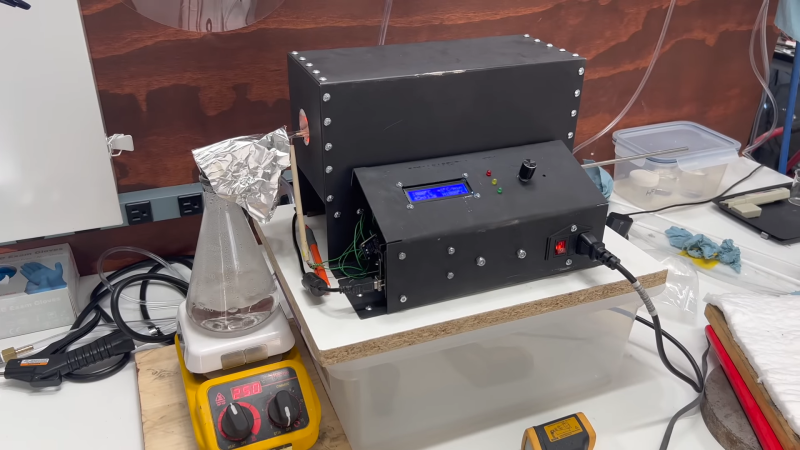
[ProjectsInFlight]’s tube furnace started with a length of heat-resistant quartz glass tubing and a small tub of sodium silicate refractory cement, from the plumbing section of any home store. The tube was given a thin coat of cement and dried in a low oven before wrapping it with nichrome wire. The wrapped tube got another, thicker layer of silicate cement and an insulating wrap of alumina ceramic wool before applying power to cure everything at 1,000° C. The cured tube then went into a custom-built sheet steel enclosure with plenty of extra insulation, along with an Arduino and a solid-state relay to control the furnace. The video below concludes with testing the furnace by growing a silicon dioxide coating on a scrap of silicon wafer. This was helped along by the injection of a few whisps of water vapor while ramping the furnace temperature up, and the results are easily visible.
[ProjectsInFlight] still needs to add seals to the tube to control the atmosphere in there, an upgrade we’ll be on the lookout for. It’s already a great start, although it might take a while to catch up to our friend [Sam Zeloof].