Investigating The Fourth Passive Component
When first learning about and building electronic circuits, the first things all of us come across are passive components such as resistors, capacitors, and inductors. These have easily-understandable properties and are used in nearly all circuits in some way or another. Eventually we’ll move on to learning about active components like transistors, but there’s a fourth passive circuit component that’s almost never encountered. Known as the memristor, this mysterious device is not quite as intuitive as the other three, so [Andrew] created an Arduino shield to investigate their properties.
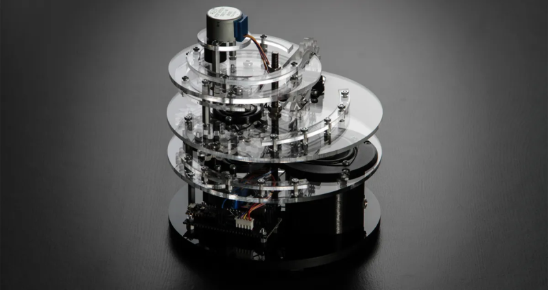
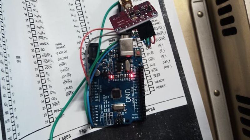
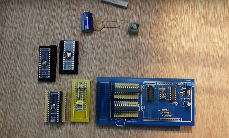
Memristors relate electric charge and magnetic flux linkage, which means that their resistance changes based on the current that passes through them. As their name implies, this means they have memory, and retain their properties even after power is removed. [Andrew] is testing three different memristors, composed of tungsten, carbon, and chromium, using this specialized test set. The rig is based on an Arduino Uno and has a few circuit components that can be used as references and generates data on the behavior of the memristors under various situations.
The memristors used here do exhibit expected behavior when driven with positive voltage signals, but did exhibit a large amount of variability when voltage was applied in a negative direction. [Andrew] speculates that using these devices for storage would be difficult and would likely require fairly bespoke applications for each type. But as the applications for these seemingly bizarre circuit components increase, we expect them to improve much like any other passive component.