Simple Circuit Keeps Process Control Loops in Tune
Spare a moment’s pity for the process engineer, whose job it is to keep industrial automation running no matter what. These poor souls seem to be forever on call, fielding panicked requests to come to the factory floor whenever the line goes down. Day or night, weekends, vacations, whatever — when it breaks, the process engineer jumps.
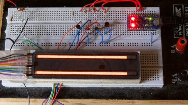
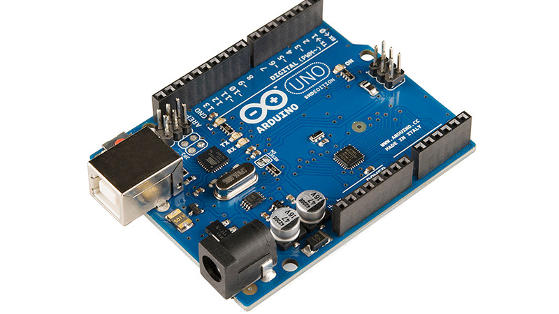
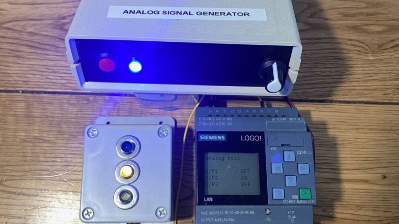
The pressures of such a gig can be enormous, and seem to have weighed on [Tom Goff] enough that he spent a weekend building a junk bin analog signal generator to replace a loop calibrator that he misplaced. Two process control signaling schemes were to be supported — the 0 to 10 VDC analog signal, and the venerable 4-20 mA current loop. All that’s needed for both outputs is an Arduino and an LM358 dual op-amp, plus a few support components. The 0-10 V signal starts as a PWM output from the Arduino, with its 0-5 V average amplified by one of the op-amps set up as a non-inverting amp with a gain of 2. With a little filtering, the voltage output is pretty stable, and swings nicely through the desired range — see the video below for that.
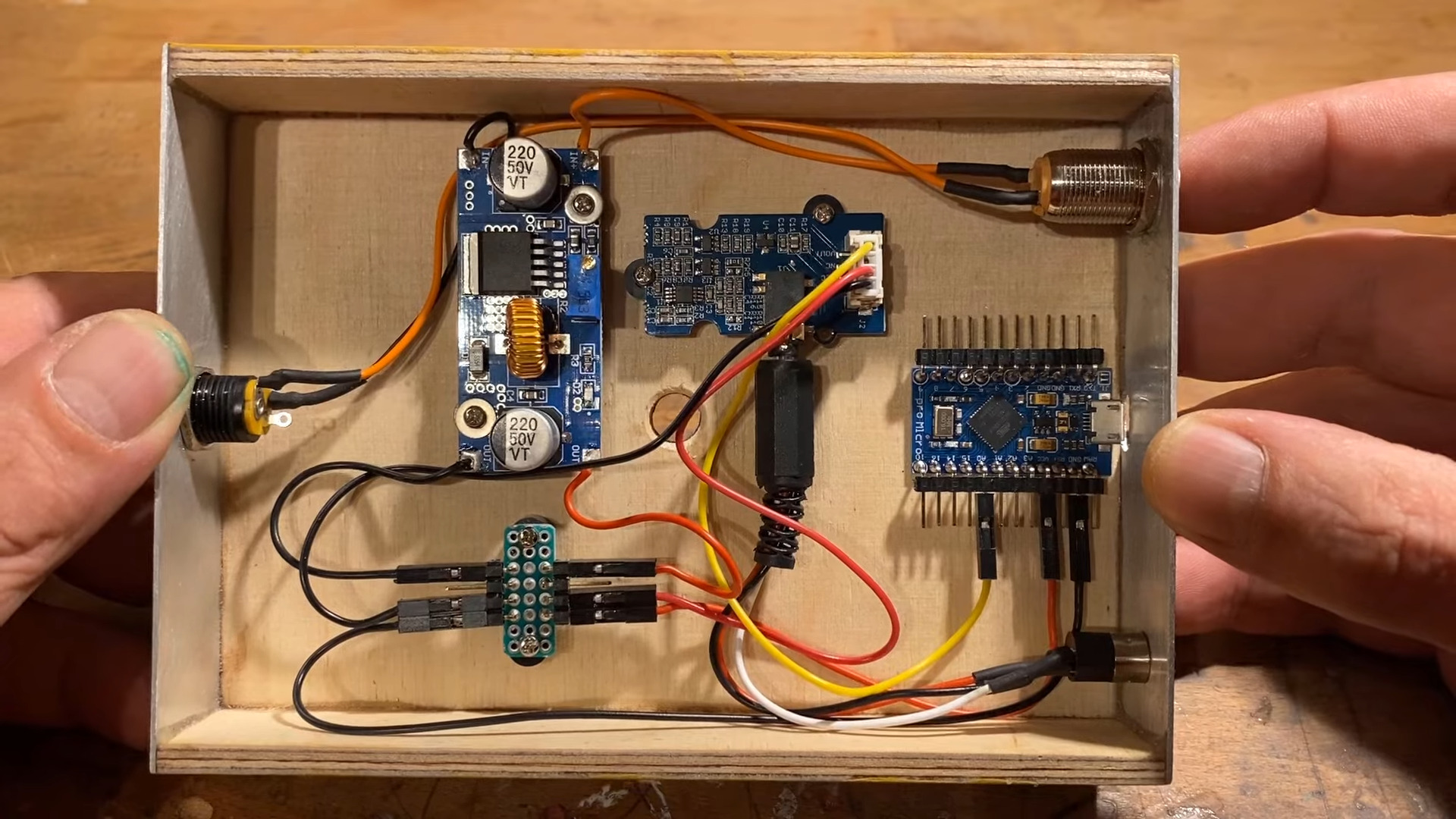
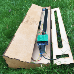
The current loop output is only slightly more complicated. An identical circuit on a separate Arduino output generates the same 10 V max output, but a code change limits the low end of the range to 1 V. This output of the op-amp is fed through a 500-Ω trimmer pot, and the magic of Ohm’s Law results in a 4-20 mA current. The circuit lives on a piece of perf board in a small enclosure and does the job it was built for — nothing fancy needed.
And spoiler alert: [Tom] found the missing loop calibrator — after he built this, of course. Isn’t that always the way?