Controlling a Broken Super Nintendo With MIDI
A Super Nintendo that has trouble showing sprites doesn’t make for a very good game system. As it turns out, Super Mario World is a lot less fun when the titular hero is invisible. So it’s no surprise that [jwotto] ended up tossing this partially functional SNES into the parts bin a few years back.
But he recently came up with a project that may actually benefit from its unusual graphical issues; turning the glitched console into a circuit bent video synthesizer. The system was already displaying corrupted visuals, so [jwotto] figured he’d just help things along by poking around inside and identifying pins that created interesting visual effects when shorted out.
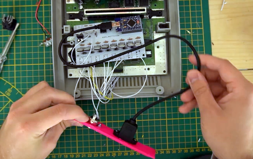
Once he mapped out the pins, he wired them all up to a transistor switching board that he’d come up with for a previous project. That would let an Arduino short out the pins on command while still keeping the microcontroller relatively isolated from the SNES. Then it was just a matter of writing some code that would fire off the transistors based on MIDI input.
The end result is a SNES that creates visual glitches along with the music, which [jwotto] can hook up to a projector when he does live shows. A particularly neat feature is that each game responds in its own way, so he can swap out the cartridge to show completely different visuals without having to change any of the MIDI sequencing.
A project like this serves as a nice introduction to both circuit bending and MIDI hacking for anyone looking to get their digital feet wet, and should pair nicely with the MIDI Game Boy Advance.
[Thanks to Irregular Shed for the tip.]