Focus Flower Motivates By Squirting Water In Your Face
When you need to get some tasks done and are short on attention, it’s hard to beat a timer. But whenever you do, it feels pretty darn good. The problem is that when you don’t finish in time, what’s the punishment? There are no consequences baked into the Pomodoro Technique other than good ol’ guilt. Wouldn’t it be better if there was a bit of negative reinforcement involved?
[Hardware Unknown]’s Focus Flower never needs watering, at least not in the normal horticultural way. You will have to fill a reservoir, because this flower provides liquid motivation. No, it’s not a spirit spritzer, though we suppose you could turn it into an avant-garde vodka fountain when the novelty of water wears off, making this Pomodoro with a twist into more of a Bloody Mary. It’s a natural next step, especially if you were already into the hot sauce idea.
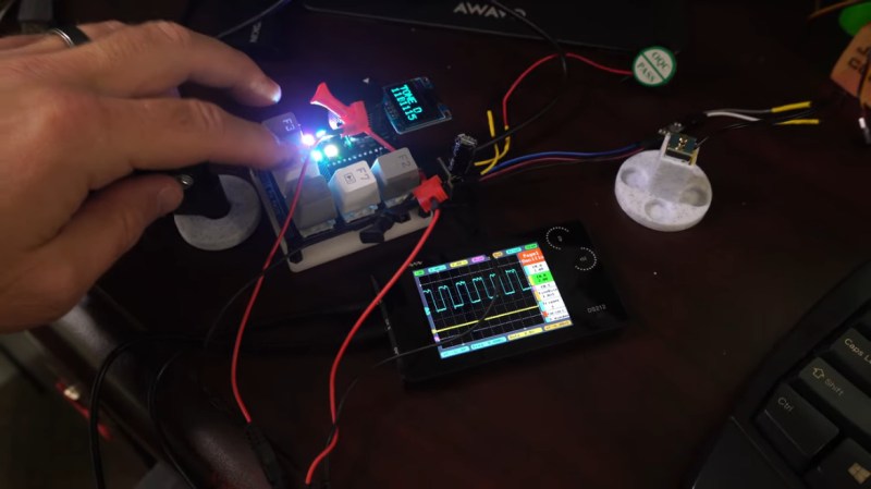
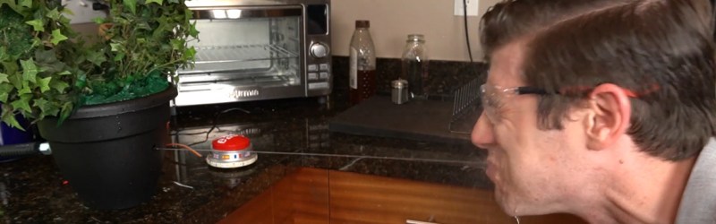
Operation Focus Flower is simple: just push the easy button to start the task timer, and the Arduino Nano attached will begin a countdown. Push the button again when you’re done, but if you don’t do it before the countdown is over, the plant squirts you with a steady, skin-blasting stream of water from a solenoid-driven flosser tip. An air compressor nearby is required, which blows the minimalist vibe a bit, but you could always stow that part underneath your desk.
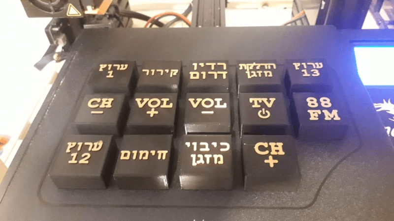
The Focus Flower sure looks to be effective at the whole negative reinforcement thing. And it doesn’t leave you totally clueless — there’s a ring of LEDs around the base that show how much time is left. Whenever you do successfully hit the button in time, it will say ‘that was easy’ in one of 12 languages, hence all the flags. Do not miss the totally free infomercial below.
Maybe you want a more friendly way to manage your time — we understand. Meet the Pomodachi productivity pet.
Via the Arduino Blog