Posts with «vintage» label

Australian Electronics Nostalgia – Talking Electronics Kits

Introduction

From 1981, Australian electrical engineer Colin Mitchell started publishing his home-grown electronics magazine “Talking Electronics”. His goal was to get people interested and learning about electronics, and more so with a focus on digital electronics. It was (and still is) a lofty goal – in which he succeeded. From a couple of rooms in his home the magazine flourished, and many projects described within were sold as kits. At one stage there were over 150 Talking Electronics kits on the market. You could find the books and kits in retail outlets such as Dick Smith Electronics, and for a short while there was a TE store in Moorabbin (Victoria). Colin and the team’s style of writing was easy to read and very understandable – but don’t take my word for it, you can download the magazines from his website (they’re near the bottom of the left column). Dave Jones recently interviewed Colin, and you can watch those for much more background information.

Over fifteen issues you could learn about blinking LEDs all the way to making your own expandable Z80 board computer, and some of the kits may still be available. Colin also published a series of tutorial books on electronics, and also single-magazine projects. And thus the subjects of our review … we came across the first of these single-issue projects from 1981 – the Mini Frequency Counter (then afterwards we have another kit):

How great is that? The PCB comes with the magazine. This is what set TE apart from the rest, and helped people learn by actually making it easy to build what was described in the magazine instead of just reading about it. For 1981 the PCB was quite good – they were silk-screened which was quite rare at the time:

And if you weren’t quite ready, the magazine also included details of a square-wave oscillator to make and a 52-page short course in digital electronics. However back to the kit…

Assembly

The kit uses common parts and I hoard CMOS ICs so building wasn’t a problem. This (original) version of the kit used LEDs instead of 7-segment displays (which were expensive at the time) so there was plenty of  careful soldering to do:

And after a while the counter started to come together. I used IC sockets just in case:

The rest was straight-forward, and before long 9 V was supplied, and we found success:

To be honest progress floundered for about an hour at this point – the display wouldn’t budge off zero. After checking the multi-vibrator output, calibrating the RC circuits and finally tracing out the circuit with a continuity tester, it turned out one of the links just wasn’t soldered in far enough – and the IC socket for the 4047 was broken So a new link and directly fitting the 4047 fixed it. You live and learn.

Operation

So – we now have a frequency counter that’s good for 100 Hz to the megahertz range, with a minimum of parts. Younger, non-microcontroller people may wonder how that is possible – so here’s the schematic:

The counter works by using a multi-vibrator using a CD4047 to generate a square-wave at 50, 500 and 5 kHz, and the three trimpots are adjusted to calibrate the output. The incoming pulses to measure are fed to the 4026 decade counter/divider ICs. Three of these operate in tandem and each divide the incoming count by ten – and display or reset by the alternating signal from the 4047. However for larger frequencies (above 900 Hz) you need to change the frequency fed to the display circuit in order to display the higher (left-most) digits of the result. A jumper wire is used to select the required level (however if you mounted the kit in a case, a knob or switch could be used).

For example, if you’re measuring 3.456 MHz you start with the jumper on H and the display reads 345 – then you switch to M to read 456 – then you switch to the L jumper and read 560, giving you 3456000 Hz. If desired, you can extend the kit with another PCB to create a 5-digit display. The counter won’t be winning any precision contests – however it has two purposes, which are fulfilled very well. It gives the reader an inexpensive piece of test equipment that works reasonably well, and a fully-documented project so the reader can understand how it works (and more).

And for the curious –  here it is in action:

[Update 20/07/2013] Siren Kit

Found another kit last week, the Talking Electronics “DIY Kit #31 – 9V siren”. It’s an effective and loud siren with true rise and fall, unlike other kits of the era that alternated between two fixed tones. The packaging was quite strong and idea for mail-order at the time:

The label sells the product (and shows the age):

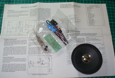
The kit included every part required to work, apart from a PP3 battery, and a single instruction sheet with a good explanation of how the circuit works, and some data about the LM358:

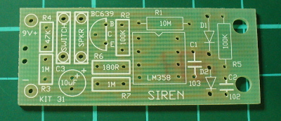
… and as usual the PCB was ahead of its’ time with full silk-screen and solder mask:

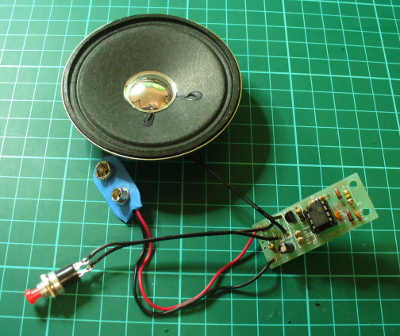
Assembly was quite straight-forward. The design is quite compact, so a lot of vertical resistor mounting was necessary due to the lack of space. However it was refreshing to not have any links to fit. After around twenty minutes of relaxed construction, it was ready to test:

It’s a 1/2 watt speaker, however much louder than originally anticipated:

Once again, another complete and well-produced kit.

Conclusion

That was a lot of fun, and I’m off to make the matching square-wave oscillator for the frequency counter. Kudos to Colin for all those years of publication and helping people learn. Lots of companies bang on about offering tutorials and information on the Internet for free, but Colin has been doing it for over ten years. Check out his Talking Electronics website for a huge variety of knowledge, an excellent electronics course you can get on CD – and go easy on him if you have any questions.

Full-sized images available on flickr. This kit was purchased without notifying the supplier.

And if you made it this far – check out my new book “Arduino Workshop” from No Starch Press.

In the meanwhile have fun and keep checking into tronixstuff.com. Why not follow things on twitterGoogle+, subscribe  for email updates or RSS using the links on the right-hand column? And join our friendly Google Group – dedicated to the projects and related items on this website. Sign up – it’s free, helpful to each other –  and we can all learn something.

The post Australian Electronics Nostalgia – Talking Electronics Kits appeared first on tronixstuff.

Tutorial – Arduino and MC14489 LED Display Driver

Learn how to use MC14489 LED display driver ICs with Arduino in chapter fifty-one of a series originally titled “Getting Started/Moving Forward with Arduino!” by John Boxall – A tutorial on the Arduino universe. The first chapter is here, the complete series is detailed here.

Updated 12/05/2013

Introduction

Recently we’ve been looking at alternatives to the MAX7219 LED display driver IC due to pricing and availability issues (stay tuned for that one) – and came across an old but still quite useful IC – the MC14489 from Motorola (now Freescale Semiconductor). The MC14489 can drive five seven-segment LED numbers with decimal point, or a combination of numbers and separate LEDs. You can also daisy-chain more than one to drive more digits, and it’s controlled with a simple serial data-clock method in the same way as a 74HC595 shift register. Sourcing the MC14489 isn’t too difficult – it’s available from element14, Newark, Digikey, and so on – or if you’re not in a hurry, try the usual suspects like Futurlec.

For the purpose of the tutorial we’ll show you how to send commands easily from your Arduino or compatible board to control a five-digit 7-segment LED display module – and the instructions are quite simple so they should translate easily to other platforms. Once you have mastered the single module, using more than one MC14489 will be just as easy. So let’s get started.

Hardware

Before moving forward, download the data sheet (pdf). You will need to refer to this as you build the circuit(s). And here’s our subject in real life:

For our demonstration display we’ll be using a vintage HP 5082-7415 LED display module. However you can use almost any 7-segment modules as long as they’re common-cathode – for example, Sparkfun part number COM-11405. If you’re using a four-digit module and want an extra digit, you can add another single digit display. If you want a ruler, the design files are here.

Connecting the MC14489 to an LED display isn’t complex at all. From the data sheet consider Figure 9:

Each of the anode control pins from the MC14489 connect to the matching anodes on your display module, and the BANK1~5 pins connect to the matching digit cathode pins on the display module. You can find the MC14489 pin assignments on page 1 of the data sheet. Seeing as this is chapter fifty-one  – by now you should be confident with finding such information on the data sheets, so I will be encouraging you to do a little more of the work.

Interesting point – you don’t need current-limiting resistors. However you do need the resistor Rx – this controls the current flow to each LED segment. But which value to use? You need to find out the forward current of your LED display (for example 20 mA) then check Figure 7 on page 7 of the data sheet:

To be conservative I’m using a value of 2k0 for Rx, however you can choose your own based on the data sheet for your display and the graph above.  Next – connect the data, clock and enable pins of the MC14489 to three Arduino digital pints – for our example we’re using 5, 6 and 7 for data, clock and enable respectively. Then it’s just 5V and GND to Arduino 5V and GND – and put a 0.1uF capacitor between 5V and GND. Before moving on double-check the connections – especially between the MC14489 and the LED display.

Controlling the MC14489

To control the display we need to send data to two registers in the MC14489 – the configuration register  (one byte) and the display register (three bytes). See page 9 of the data sheet for the overview. The MC14489 will understand that if we send out one byte of data it is to send it the configuration register, and if it receives three bytes of data to send it to the display register. To keep things simple we’ll only worry about the first bit (C0) in the configuration register – this turns the display outputs on or off. To do this, use the following:

digitalWrite(enable, LOW);
shiftOut(data, clock, MSBFIRST, B00000001); // used binary for clarity, however you can use decimal or hexadecimal numbers
digitalWrite(enable, HIGH);
delay(10);

and to turn it off, send bit C0 as zero. The small delay is necessary after each command.

Once you have turned the display on – the next step is to send three bytes of data which represent the numbers to display and decimal points if necessary. Review the table on page 8 of the data sheet. See how they have the binary nibble values for the digits in the third column. Thankfully the nibble for each digit is the binary value for that digit. Furthermore you might want to set the decimal point – that is set using three bits in the first nibble of the three bytes (go back to page 9 and see the display register). Finally you can halve the brightness by setting the very first bit to zero (or one for full brightness).

As an example for that – if you want to display 5.4321 the three bytes of data to send in binary will be:

1101 0101 0100 0011 0010 0001

Let’s break that down. The first bit is 1 for full brightness, then the next three bits (101) turn on the decimal point for BANK5 (the left-most digit). Then you have five nibbles of data, one for each of the digits from left to right. So there’s binary for 5, then four, then three, then two, then one.

digitalWrite(enable, LOW); 
shiftOut(data, clock, MSBFIRST, B11010101); // D23~D16 
shiftOut(data, clock, MSBFIRST, B01000011); // D15~D8
shiftOut(data, clock, MSBFIRST, B00100001); // D7~D0
digitalWrite(enable, HIGH);
delay(10);

To demonstrate everything described so far, it’s been neatly packaged into our first example sketch:

// Example 51.1
// Motorola MC14489 with HP 5082-7415 5-digit, 7-segment LED display
// 2k0 resistor on MC14489 Rx pin
// John Boxall 2013 CC by-sa-nc
// define pins for data from Arduino to MC14489
// we treat it just like a 74HC595
int data = 5;
int clock = 6;
int enable = 7;
void setup()
{
 pinMode(data, OUTPUT);
 pinMode(enable, OUTPUT);
 pinMode(clock, OUTPUT);
 displayOn(); // display defaults to off at power-up
}
void displayTest1()
// displays 5.4321
{
 digitalWrite(enable, LOW); // send 3 bytes to display register. See data sheet page 9
 // you can also insert decimal or hexadecimal numbers in place of the binary numbers
 // we're using binary as you can easily match the nibbles (4-bits) against the table
 // in data sheet page 8
 shiftOut(data, clock, MSBFIRST, B11010101); // D23~D16
 shiftOut(data, clock, MSBFIRST, B01000011); // D15~D8
 shiftOut(data, clock, MSBFIRST, B00100001); // D7~D0
 digitalWrite(enable, HIGH);
 delay(10);
}
void displayTest2()
// displays ABCDE
{
 digitalWrite(enable, LOW); // send 3 bytes to display register. See data sheet page 9
 // you can also insert decimal or hexadecimal numbers in place of the binary numbers
 // we're using binary as you can easily match the nibbles (4-bits) against the table
 // in data sheet page 8
 shiftOut(data, clock, MSBFIRST, B10001010); // D23~D16
 shiftOut(data, clock, MSBFIRST, B10111100); // D15~D8
 shiftOut(data, clock, MSBFIRST, B11011110); // D7~D0
 digitalWrite(enable, HIGH);
 delay(10);
}
void displayOn()
// turns on display
{
 digitalWrite(enable, LOW);
 shiftOut(data, clock, MSBFIRST, B00000001);
 digitalWrite(enable, HIGH);
 delay(10);
}
void displayOff()
// turns off display
{
 digitalWrite(enable, LOW);
 shiftOut(data, clock, MSBFIRST, B00000000);
 digitalWrite(enable, HIGH);
 delay(10);
}
void loop()
{
 displayOn();
 displayTest1();
 delay(1000);
 displayTest2();
 delay(1000);
 displayOff();
 delay(500);
}

… with the results in the following video:


Now that we can display numbers and a few letters with binary, life would be easier if there was a way to take a number and just send it to the display.

So consider the following function that takes an integer between 0 and 99999, does the work and sends it to the display:

void displayIntLong(long x)
// takes a long between 0~99999 and sends it to the MC14489
{
 int numbers[5];
 byte a=0; 
 byte b=0; 
 byte c=0; // will hold the three bytes to send to the MC14489 

 // first split the incoming long into five separate digits
 numbers[0] = int ( x / 10000 ); // left-most digit (will be BANK5)
 x = x % 10000; 
 numbers[1] = int ( x / 1000 );
 x = x % 1000; 
 numbers[2] = int ( x / 100 );
 x = x % 100; 
 numbers[3] = int ( x / 10 );
 x = x % 10; 
 numbers[4] = x % 10; // right-most digit (will be BANK1)

 // now to create the three bytes to send to the MC14489
 // build byte c which holds digits 4 and 5
 c = numbers[3];
 c = c << 4; // move the nibble to the left
 c = c | numbers[4];
 // build byte b which holds digits 3 and 4
 b = numbers [1];
 b = b << 4;
 b = b | numbers[2];
 // build byte a which holds the brightness bit, decimal points and digit 1
 a = B10000000 | numbers[0]; // full brightness, no decimal points

 // now send the bytes to the MC14489
 digitalWrite(enable, LOW);
 shiftOut(data, clock, MSBFIRST, a);
 shiftOut(data, clock, MSBFIRST, b);
 shiftOut(data, clock, MSBFIRST, c); 
 digitalWrite(enable, HIGH);
 delay(10); 
}

So how does that work? First it splits the 5-digit number into separate digits and stores them in the array numbers[]. It then places the fourth digit into a byte, then moves the data four bits to the left – then we bitwise OR the fifth digit into the same byte. This leaves us with a byte of data containing the nibbles for the fourth and fifth digit. The process is repeated for digits 2 and 3. Finally the brightness bit and decimal point bits are assigned to another byte which then has the first digit’s nibble OR’d into it. Which leaves us with bytes a, b and c ready to send to the MC14489. Note that there isn’t any error-checking – however you could add a test to check that the number to be displayed was within the parameter, and if not either switch off the display (see example 51.1) or throw up all the decimal points or … whatever you want.

You can download the demonstration sketch for the function – Example 51.2, and view the results in the following video:

You can also display the letters A to F by sending the values 10 to 15 respectivel to each digit’s nibble. However that would be part of a larger application, which you can (hopefully) by now work out for yourself. Furthermore there’s some other characters that can be displayed – however trying to display the alphabet using 7-segment displays is somewhat passé. Instead, get some 16-segment LED modules or an LCD.

Finally, you can cascade more than one MC14489 to control more digits. Just run a connection from the data out pin on the first MC14889 to the data pin of the second one, and all the clock and enable lines together. Then send out more data – see page 11 of the data sheet. If you’re going to do that in volume other ICs may be a cheaper option and thus lead you back to the MAX7219.

Conclusion

For a chance find the MC14489 is a fun an inexpensive way to drive those LED digit displays. We haven’t covered every single possible option or feature of the part – however you will now have the core knowledge to go further with the MC14489 if you need to move further with it. And if you enjoy my tutorials, or want to introduce someone else to the interesting world of Arduino – check out my new book “Arduino Workshop” from No Starch Press.

In the meanwhile have fun and keep checking into tronixstuff.com. Why not follow things on twitterGoogle+, subscribe  for email updates or RSS using the links on the right-hand column? And join our friendly Google Group – dedicated to the projects and related items on this website. Sign up – it’s free, helpful to each other –  and we can all learn something.

The post Tutorial – Arduino and MC14489 LED Display Driver appeared first on tronixstuff.

Phone Booth becomes a Photo Booth

A project by Chris Bell, Liangjie Xia, and Mike Kelberman called Rotobooth is a hacked rotary phone that takes your picture as you’re calling your own cell phone, then sends a link of the photos to you by SMS.

The rotary phone was hacked using Arduino, the photos were collected on a Flickr page, and finally the SMS notification is sent using Twilio. The exterior design is clean (dig the orange phone!) and recently took 3rd place at Twilio’s Photohack Day 2.

[via Twilio]

More: