Posts with «uno» label

A DIY water-saving device

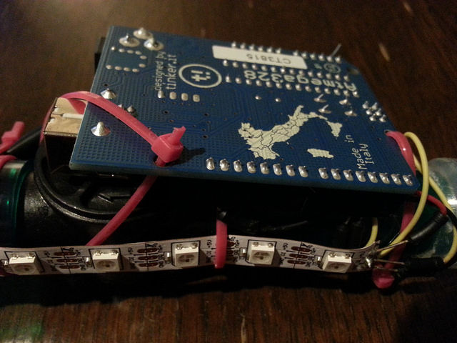
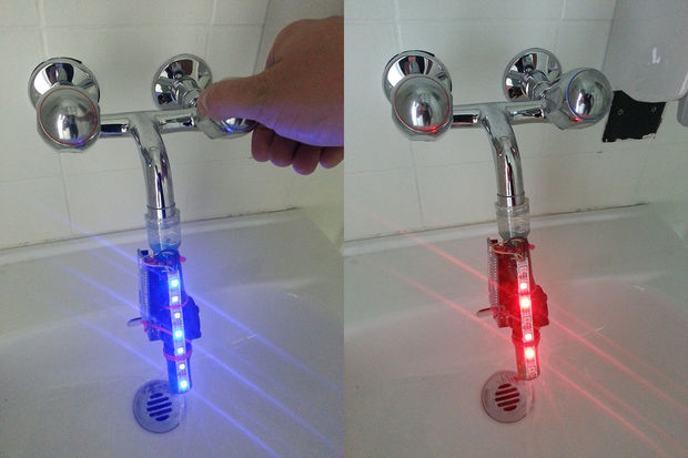
Last June Thomas Amberg participated to Water Hackathon – Open Source Technologies for Rivers, Oceans and Lakes taking place in Lausanne. He came up with a DIY solution made with Arduino Uno and a flow sensor to help monitor how much water a tub consumes.

The Augmented Water device helps you save water by turning red after one Liter and helping you not to waste it unnecessarily.
The ingredients you need to reach the results are the following: an Arduino Uno, Adafruit Neopixels, Flow sensor, LiPo battery, LiPo charger, jumper wires, tube fitting the sensor, plastic test tube and some zip ties. You can easily make one in 6 steps with his tutorial on Instructables.

Arduino Blog 09 Jul 19:50

Autonomous Racers!!!

Primary image

What does it do?

Race each other around the room

Hello everyone, I’ve posted a lot on LMR, and I build robots for a living, but this is the first time I’ve built a personal robot that I’m able to tell you all about. First off, I got this idea from Fritsl (http://letsmakerobots.com/node/928 ) and I decided I wanted to build a pair of wall racers for my nephew who has always asked me to build him some robots. If you’ve never heard of a wall racer it is a modified RC car with two sonars, one pointing forward the other pointing to one side.

Cost to build

Embedded video

Finished project

Complete

Number

Time to build

Type

wheels

URL to more information

Weight

read more

Tutorial – Arduino and ILI9325 colour TFT LCD modules

Learn how to use inexpensive ILI9325 colour TFT LCD modules in chapter fifty of a series originally titled “Getting Started/Moving Forward with Arduino!” by John Boxall – A tutorial on the Arduino universe. The first chapter is here, the complete series is detailed here.

Introduction

Colour TFT LCD modules just keep getting cheaper, so in this tutorial we’ll show you how to get going with some of the most inexpensive modules we could find. The subject of our tutorial is a 2.8″ 240 x 320 TFT module with the ILI9325 LCD controller chip. If you look in ebay this example should appear pretty easily, here’s a photo of the front and back to help identify it:

There is also the line “HY-TFT240_262k HEYAODZ110510” printed on the back of the module. They should cost less than US$10 plus shipping. Build quality may not be job number one at the factory so order a few, however considering the cost of something similar from other retailers it’s cheap insurance. You’ll also want sixteen male to female jumper wires to connect the module to your Arduino.

Getting started

To make life easier we’ll use an Arduino library “UTFT” written for this and other LCD modules. It has been created by Henning Karlsen and can be downloaded from his website. If you can, send him a donation – this library is well worth it. Once you’ve downloaded and installed the UTFT library, the next step is to wire up the LCD for a test.

Run a jumper from the following LCD module pins to your Arduino Uno (or compatible):

  • DB0 to DB7 > Arduino D0 to D7 respectively
  • RD > 3.3 V
  • RSET > A2
  • CS > A3
  • RW > A4
  • RS > A5
  • backlight 5V > 5V
  • backlight GND > GND

Then upload the following sketch – Example 50.1. You should be presented with the following on your display:

If you’re curious, the LCD module and my Eleven board draws 225 mA of current. If that didn’t work for you, double-check the wiring against the list provided earlier. Now we’ll move forward and learn how to display text and graphics.

Sketch preparation

You will always need the following before void setup():

#include "UTFT.h"
UTFT myGLCD(ILI9325C,19,18,17,16); // for Arduino Uno

and in void setup():

myGLCD.InitLCD(orientation); 
myGLCD.clrScr();

with the former command, change orientation to either LANDSCAPE to PORTRAIT depending on how you’ll view the screen. You may need further commands however these are specific to features that will be described below. The function .clrScr() will clear the screen.

Displaying Text

There are three different fonts available with the library. To use them add the following three lines before void setup():

extern uint8_t SmallFont[];
extern uint8_t BigFont[];
extern uint8_t SevenSegNumFont[];

When displaying text you’ll need to define the foreground and background colours with the following:

myGLCD.setColor(red, green, blue); 
myGLCD.setBackColor(red, green, blue);

Where red, green and blue are values between zero and 255. So if you want white use 255,255,255 etc. For some named colours and their RGB values, click here. To select the required font, use one of the following:

myGLCD.setFont(SmallFont); // Allows 20 rows of 40 characters
myGLCD.setFont(BigFont); // Allows 15 rows of 20 characters
myGLCD.setFont(SevenSegNumFont); // allows display of 0 to 9 over four rows

Now to display the text use the function:

myGLCD.print("text to display",x, y);

where text is what you’d like to display, x is the horizontal alignment (LEFT, CENTER, RIGHT) or position in pixels from the left-hand side of the screen and y is the starting point of the top-left of the text. For example, to start at the top-left of the display y would be zero. You can also display a string variable instead of text in inverted commas.

You can see all this in action with the following sketch – Example 50.2, which is demonstrated in the following video:

Furthremore, you can also specify the angle of display, which gives a simple way of displaying text on different slopes. Simply add the angle as an extra parameter at the end:

myGLCD.print("Hello, world", 20, 20, angle);

Again, see the following sketch – Example 50.2a, and the results below:

Displaying Numbers

Although you can display numbers with the text functions explained previously, there are two functions specifically for displaying integers and floats.

You can see these functions in action with the following sketch – Example 50.3, with an example of the results below:

Displaying Graphics

There’s a few graphic functions that can be used to create required images. The first is:.

myGLCD.fillScr(red, green, blue);

which is used the fill the screen with a certain colour. The next simply draws a pixel at a specified x,y location:

myGLCD.drawPixel(x,y);

Remember that the top-left of the screen is 0,0. Moving on, to draw a single line, use:

myGLCD.drawLine(x1,0,x2,239);

where the line starts at x1,y1 and finishes at x2,y2. Need a rectangle? Use:

myGLCD.drawRect(x1,y2,x2,y2); // for open rectangles
myGLCD.fillRect(x1,y2,x2,y2); // for filled rectangles

where the top-left of the rectangle is x1,y1 and the bottom-right is x2, y2. You can also have rectangles with rounded corners, just use:

myGLCD.drawRoundRect(x1,y2,x2,y2); // for open rectangles
myGLCD.fillRoundRect(x1,y2,x2,y2); // for filled rectangles

instead. And finally, circles – which are quite easy. Just use:

myGLCD.drawCircle(x,y,r); // draws open circle
myGLCD.fillCircle(x,y,r); // draws a filled circle

where x,y are the coordinates for the centre of the circle, and r is the radius. For a quick demonstration of all the graphic functions mentioned so far, see Example 50.4 – and the following video:

Displaying bitmap images

If you already have an image in .gif, .jpg or .png format that’s less than 300 KB in size, this can be displayed on the LCD. To do so, the file needs to be converted to an array which is inserted into your sketch. Let’s work with a simple example to explain the process. Below is our example image:

Save the image of the puppy somewhere convenient, then visit this page. Select the downloaded file, and select the .c and Arduino radio buttons, then click “make file”. After a moment or two a new file will start downloading. When it arrives, open it with a text editor – you’ll see it contains a huge array and another #include statement – for example:

Past the #include statement and the array into your sketch above void setup(). After doing that, don’t be tempted to “autoformat” the sketch in the Arduino IDE. Now you can use the following function to display the bitmap on the LCD:

myGLCD.drawBitmap(x,y,width,height, name, scale);

Where x and y are the top-left coordinates of the image, width and height are the … width and height of the image, and name is the name of the array. Scale is optional – you can double the size of the image with this parameter. For example a value of two will double the size, three triples it – etc. The function uses simple interpolation to enlarge the image, and can be a clever way of displaying larger images without using extra memory. Finally, you can also display the bitmap on an angle – using:

myGLCD.drawBitmap(x,y,width,height, name, angle, cx, cy);

where angle is the angle of rotation and cx/cy are the coordinates for the rotational centre of the image.

The bitmap functions using the example image have been used in the following sketch – Example 50.5, with the results in the following video:

Unfortunately the camera doesn’t really do the screen justice, it looks much better with the naked eye.

What about the SD card socket and touch screen?

The SD socket didn’t work, and I won’t be working with the touch screen at this time.

Conclusion

So there you have it – an incredibly inexpensive and possibly useful LCD module. Thank you to Henning Karlsen for his useful library, and if you found it useful – send him a donation via his page.

In the meanwhile have fun and keep checking into tronixstuff.com. Why not follow things on twitterGoogle+, subscribe  for email updates or RSS using the links on the right-hand column? And join our friendly Google Group – dedicated to the projects and related items on this website. Sign up – it’s free, helpful to each other –  and we can all learn something.

The post Tutorial – Arduino and ILI9325 colour TFT LCD modules appeared first on tronixstuff.
Tronixstuff 26 Apr 02:31

ADXL345 graphing program in Processing

OK, so I got this nice little sensor, the ADXL345 and I have composed it into a new version of my "shield".


read more

Let's Make Robots 11 Oct 18:25
adxl345  arduino  processing  uno  

StomperDrino

Primary image

What does it do?

Navigates around the room detecting obstacles and avoiding them.

I got this book for my Kindle over amazon Insectronics: Build Your Own Walking Robot and decided for this to be my first robot project. As i have been dealing with arduino for some time now but mostly building advanced outdoor sensor networks using long range RF. The book has it all from cutting the parts to programming the PIC they used to control the robot. I made a arduino version since i have a lot of arduinos at home.

Future addons:

- Use a arduino nano with a homemade servo shield to downsize the electronics

Cost to build

$120,00

Embedded video

Finished project

Number

Time to build

48 hours

Type

legs

URL to more information

Weight

read more

Brabenec

Primary image

What does it do?

follow wall/avoid obstacles

Overview

We are building this robot with my friend. It is (when finalized) supposed to be able to detect metal objects and interact with them (move them, ideally...). So far it has only two IR sensors for obstacle detection, so no metal detection.


Cost to build

Embedded video

Finished project

Number

Time to build

Type

tracks

URL to more information

Weight

read more

UnoJoy – A USB Joystick for Mac, PC, Linux or PS3

There are people who use the Arduino for some serious electronics related stuff.

Then, there are folks who use it just for fun. Alan Chatham and his team over at UnoJoy have developed a concept for Arduino Uno based USB Controllers.


Here is an excerpt of our interview with Alan:

Me: What made you choose the Arduino Uno as the heart of the controller? There are many development boards available which incorporate an ATmega8U2/16U2 or even 32U2.

Alan: This is easy – everyone loves Arduino!  It comes down to ease of use and reach.  Our primary goal with this project is to make a tool that is both easy to use and accessible.  There’s lots of code out there to make joysticks with other chips, but all the Atmel USB chips are surface-mount, and they all need a whole big toolchain to use. Plus, USB is super-complicated, and we want to encourage people, even non-technical ones, to spend their time thinking up really sweet new ways to play games, not trying to figure out what an HID descriptor is for.  On the reach side of things, Arduino is a perfect platform – even those of us that love our inline assembly and fuse settings tend to have an Arduino around for quick prototyping, and of course, Arduino’s a great platform for students and designers.


Me: Any problems that you faced while developing the prototype?

Alan: I think the biggest challenge we faced was to make it much easier for non-experts to do some more complicated things, like re-flash the ATmega8u2 on the Arduino. Let’s face it, any instructions that open up with ‘First, install XCode’ aren’t exactly user-friendly. In that vein, I put together some simple one-click batch files for installing the appropriate drivers on Windows and OSX, as well as ones for reflashing the ATmega8u2 chip between Arduino and UnoJoy firmwares.  It’s still not as simple as I’d like, so if anyone out there is handy with basic OSX GUI application programming, or the program installation chain on Windows, drop me a line!

In the end, we’re hoping that our code and examples can inspire other designers and builders and gamers to make some really awesome controllers. If they do, I of course encourage them to send their pictures and videos our way, at unojoy.tumblr.com!

Now, you too can make yourself a USB Joystick/ Gamepad/ Controller by choosing any form of input that the Arduino boards can understand. The source code and all the necessary download files are available at Google Code. Don’t forget to check out the Controller for Gran Turismo:


Thank you Alan for sharing a wonderful project with us.

Programming an Arduino in C.

I know my new robot runs (and runs nicely) on a ZBasic chp, but I will always have a great fondness for the Arduino, the first microcontroller board I ever used. (I used the PICAXE for a while too.)

Right now I have been programming a Arduino Uno with C. I really like the MikroC AVR C from Mikroelectronika. I am using the free version (limited to like 4k, decent space for C programs!). The full version is kind of pricey.

I then use AVRdude (love that name) to send the resulting hex file to the Arduino non-volitile memory. Works great!

read more

Let's Make Robots 12 Apr 17:00
arduino  avr  c  compiler  programming  uno  zbasic  

Poor Man's Colour Detector (Part 2) - The project

In this project we will be detecting the colour of 3 different Mega Blok colours (Red, Yellow and Green). We will be using an Arduino UNO connected to  2 LEDs (one Yellow and one Red LED) as light detectors, and an RGB LED to illuminate the subject. We will use a Photocell to account for varying ambient light levels. 

The signals from the LED light sensors will be sent to a Processing.org program via a Serial command. The computer program will make use of my Neural Network to classify the pattern of results and hopefully provide the correct colour "answer". The program should change the colour of the computer screen background to coincide with the colour of the Mega Blok.

The Video


Parts Required:

  • Arduino UNO...........x1   
  • Red LED .................x1
  • Yellow LED.............x1
  • 330 Ohm resistors... x 5  (for the LEDs)
  • Photocell .................x1
  • 10K Ohm resistor....x1   (for the Photocell)
  • Around 11 wires and a Breadboard (or two) to put it all together


Here is the Fritzing Sketch:   (made with Fritzing)


The Arduino Code

Load the following code into the Arduino.


arduino code Arduino: Colour Detector

01
02
03
04
05
06
07
08
09
10
11
12
13
14
15
16
17
18
19
20
21
22
23
24
25
26
27
28
29
30
31
32
33
34
35
36
37
38
39
40
41
42
43
44
45
46
47
48
49
50
51
52
53
54
55
56
57
58
59
60
61
62
63
64
65
66
67
68
69
70
71
72
73
74
75
76
77
78
79
80
81
82
83
84
85
86
87
88
89
90
91
92
93
94
95
96
97
98
99
100
101
102
103
104
105
106
107
108
109
110
111
112
113
114
/* Define the pin for the PhotoResistor */
#define PhotoR_Pin 0

/* Define the pins for the Red LED Sensor */
#define Red_LED_Sensor_POS 4
#define Red_LED_Sensor_NEG 5

/* Define the pins for the Yellow LED Sensor */
#define Yellow_LED_Sensor_POS 7
#define Yellow_LED_Sensor_NEG 8

/* Define the pin for the RGB LED torch */
#define RGB_LED_RedPin 11
#define RGB_LED_GreenPin 10
#define RGB_LED_BluePin 9

/* Controls the brightness of the RGB LED */
int intensity=255;


/* Define the maximum cycles/time allowed for each LED to capture light */
long max_darkness=80000;


void setup(){
/* Setup the RED LED Sensor */
pinMode(Red_LED_Sensor_POS,OUTPUT);
digitalWrite(Red_LED_Sensor_POS,LOW);

/* Setup the YELLOW LED Sensor */
pinMode(Yellow_LED_Sensor_POS,OUTPUT);
digitalWrite(Yellow_LED_Sensor_POS,LOW);

/* No need to setup the RGB LED Pins */

/* Turn on Serial Protocol */
Serial.begin(9600);
}

void loop()
{
byte byteRead;

/* check if data has been sent from the computer: */
if (Serial.available()) {

/* read the most recent byte (which will be from 0 to 255): */
byteRead = Serial.read();

if(byteRead==0){

/* Turn off if the byte Read was 0 */
set_RGB_LED(0,0,0,false);

}else{

/* set the brightness of the LED and then take readings: */
set_RGB_LED(0,0,0,false);
photoR_Read();
set_RGB_LED(0,0,0,true);
set_RGB_LED(intensity,0,0,true);
set_RGB_LED(0,intensity,0,true);
set_RGB_LED(0,0,intensity,true);
}
}
}

void photoR_Read(){
int ambiLight = analogRead(PhotoR_Pin);
ambiLight = map(ambiLight, 0, 900, 0, 50);
ambiLight = constrain(ambiLight, 0, 50);

/* Print the Ambient light level to the serial port */
Serial.println(ambiLight);
}

void set_RGB_LED(int redInt, int greenInt, int blueInt, boolean takeReadings ){
/* set the brightness and colour of the RGB LED: */
analogWrite(RGB_LED_RedPin, redInt);
analogWrite(RGB_LED_GreenPin, greenInt);
analogWrite(RGB_LED_BluePin, blueInt);

/* If takeReadings is true - then take Readings. */
if(takeReadings){

/* Read the amount of Yellow light */
read_LED('Y', Yellow_LED_Sensor_NEG);

/* Read the amount of Red light */
read_LED('R', Red_LED_Sensor_NEG);
}
}

void read_LED(char LED_Colour, int LED_Pin){

/* Charge the LED by applying voltage in the opposite direction */
pinMode(LED_Pin,OUTPUT);
digitalWrite(LED_Pin,HIGH);

/* Read the amount of Light coming into the LED sensor */
long darkness=0;
int lightLevel=0;
pinMode(LED_Pin,INPUT);
digitalWrite(LED_Pin,LOW);

while((digitalRead(LED_Pin)!=0) && darkness < max_darkness){
darkness++;
}

lightLevel=((max_darkness-darkness)+1)/80;

/* Print the light level to the serial port */
Serial.println(lightLevel);
}


The Processing Code:

The processing code is very long:
Please visit this link to copy and paste the code into your Processing sketch.
http://www.openprocessing.org/visuals/?visualID=34210

Make sure to select "Source Code" when you get there: (as displayed below)


If you have any problems with accessing the code - please let me know in the comments section of this blog.


This sketch utilises a simple feed forward Neural Network (that I developed from scratch). For more detailed information about this neural network please navigate through my previous blog postings.

Neural Network


So there you go, a simple idea, a simple outcome, and a lot of "stuff" happening in the background.
I am sorry. This project is not basic, but hopefully someone out there will get some use out of it.

Have fun !

ScottC

n/a