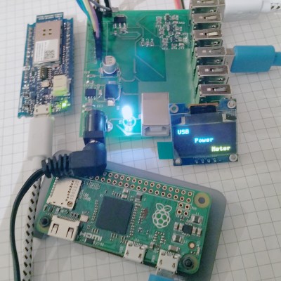
[Aleksejs Mirnijs] needed a tool to accurately measure the power consumption of his Raspberry Pi and Arduino projects, which is an important parameter for dimensioning adequate power supplies and battery packs. Since most SBC projects require a USB hub anyway, he designed a smart, WiFi-enabled 4-port USB hub that is also a power meter – his entry for this year’s Hackaday Prize.
[Aleksejs’s] design is based on the FE1.1s 4-port USB 2.0 hub controller, with two additional ports for charging. Each port features an LT6106 current sensor and a power MOSFET to individually switch devices on and off as required. An Atmega32L monitors the bus voltage and current draw, switches the ports and talks to an ESP8266 module for WiFi connectivity. The supercharged hub also features a display, which lets you read the measured current and power consumption at a glance.
Unlike most cheap hubs out there, [Aleksejs’s] hub has a properly designed power path. If an external power supply is present, an onboard buck converter actively regulates the bus voltage while a power path controller safely disconnects the host’s power line. Although the first prototype is are already up and running, this project is still under heavy development. We’re curious to see the announced updates, which include a 2.2″ touchscreen and a 3D-printable enclosure.
Blood glucose monitors are pretty ubiquitous today. For most people with diabetes, these cheap and reliable sensors are their primary means of managing their blood sugar. But what is the enterprising diabetic hacker to do if he wakes up and realizes, with horror, that a primary aspect of his daily routine doesn’t involve an Arduino?
Rather than succumb to an Arduino-less reality, he can hopefully use the shield [M. Bindhammer] is working on to take his glucose measurement into his own hands.
[Bindhammer]’s initial work is based around the popular one-touch brand of strips. These are the cheapest, use very little blood, and the included needle is not as bad as it could be. His first challenge was just getting the connector for the strips. Naturally he could cannibalize a monitor from the pharmacy, but for someone making a shield that needs a supply line, this isn’t the best option. Surprisingly, the connectors used aren’t patented, so the companies are instead just more rigorous about who they sell them to. After a bit of work, he managed to find a source.
The next challenge is reverse engineering the actual algorithm used by the commercial sensor. It’s challenging. A simple mixture of water and glucose, for example, made the sensor throw an error. He’ll get it eventually, though, making this a great entry for the Hackaday Prize.
Every machine has its own way of communicating with its operator. Some send status emails, some illuminate, but most of them vibrate and make noise. If it hums happily, that’s usually a good sign, but if it complains loudly, maintenance is overdue. [Ariel Quezada] wants to make sense of machine vibrations and draw conclusions about their overall mechanical condition from them. With his project, a 3-axis Open Source FFT Spectrum Analyzer he is not only entering the Hackaday Prize 2016 but also the highly contested field of acoustic defect recognition.
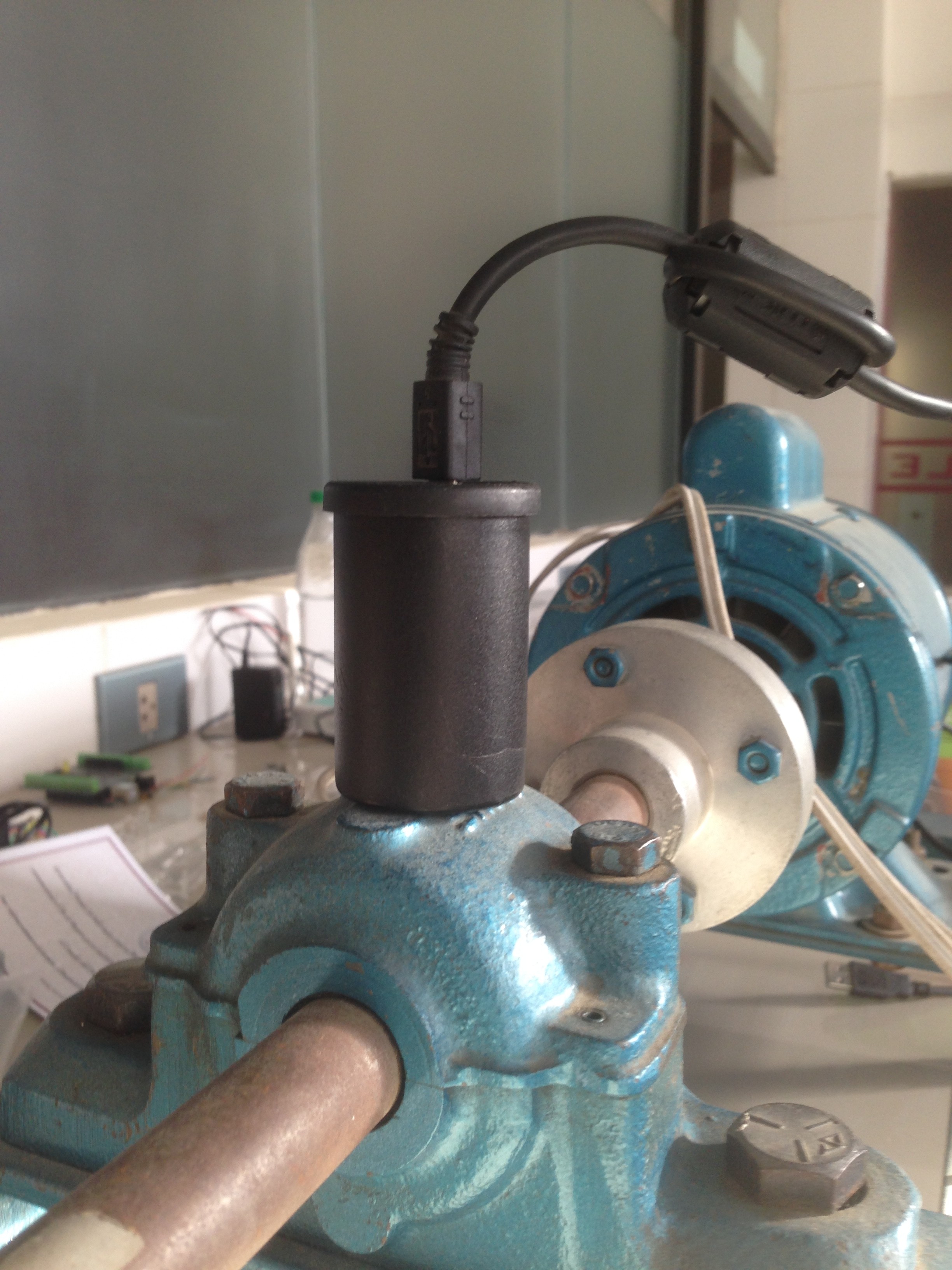
For the hardware side of the spectrum analyzer, [Ariel] equipped an Arduino Nano with an ADXL335 accelerometer, which is able to pick up vibrations within a frequency range of 0 to 1600 Hz on the X and Y axis. A film container, equipped with a strong magnet for easy installation, serves as an enclosure for the sensor. The firmware [Ariel] wrote is an efficient piece of code that samples the analog signals from the accelerometer in a free running loop at about 5000 Hz. It streams the digitized waveforms to a host computer over the serial port, where they are captured and stored by a Python script for further processing.
From there, another Python script filters the captured waveform, applies a window function, calculates the Fourier transform and plots the spectrum into a graph. With the analyzer up and running, [Ariel] went on testing the device on a large bearing of an arbitrary rotating machine he had access to. A series of tests that involved adding eccentric weights to the rotating shaft shows that the analyzer already makes it possible to discriminate between different grades of imbalance.
[adam] is a caver, meaning that he likes to explore caves and map their inner structure. This is still commonly done using traditional tools, such as notebooks (the paper ones), tape measure, compasses, and inclinometers. [adam] wanted to upgrade his equipment, but found that industrial LiDAR 3D scanners are quite expensive. His Hackaday Prize entry, the Open LIDAR, is an affordable alternative to the expensive industrial 3D scanning solutions out there.
The 3D scan of a small cave near Louisville from [caver.adam’s] Sketchfab repositoryLiDAR — Light Detection And Ranging — is the technology that senses the distance between a sensor and an object by reflectively measuring the time of flight of a light beam between the two. By acquiring a two-dimensional array of multiple distance readings, this can be used for 3D scanning. Looking at how the industrial LiDAR scanners capture the environment using fast spinning mirrors, [adam] realized that he could basically achieve the same by using a cheap laser range finder strapped to a pan and tilt gimbal.
The gimbal he designed for this task uses stepper motors to aim an SF30-B laser rangefinder. An Arduino controls the movement and lets the eye of the sensor scan an object or an entire environment. By sampling the distance readings returned by the sensor, a point cloud is created which then can be converted into a 3D model. [adam] plans to drive the stepper motors in microstepping mode to increase the resolution of his scanner. We’re looking forwards to see the first renderings of 3D cave maps captured with the Open LIDAR.
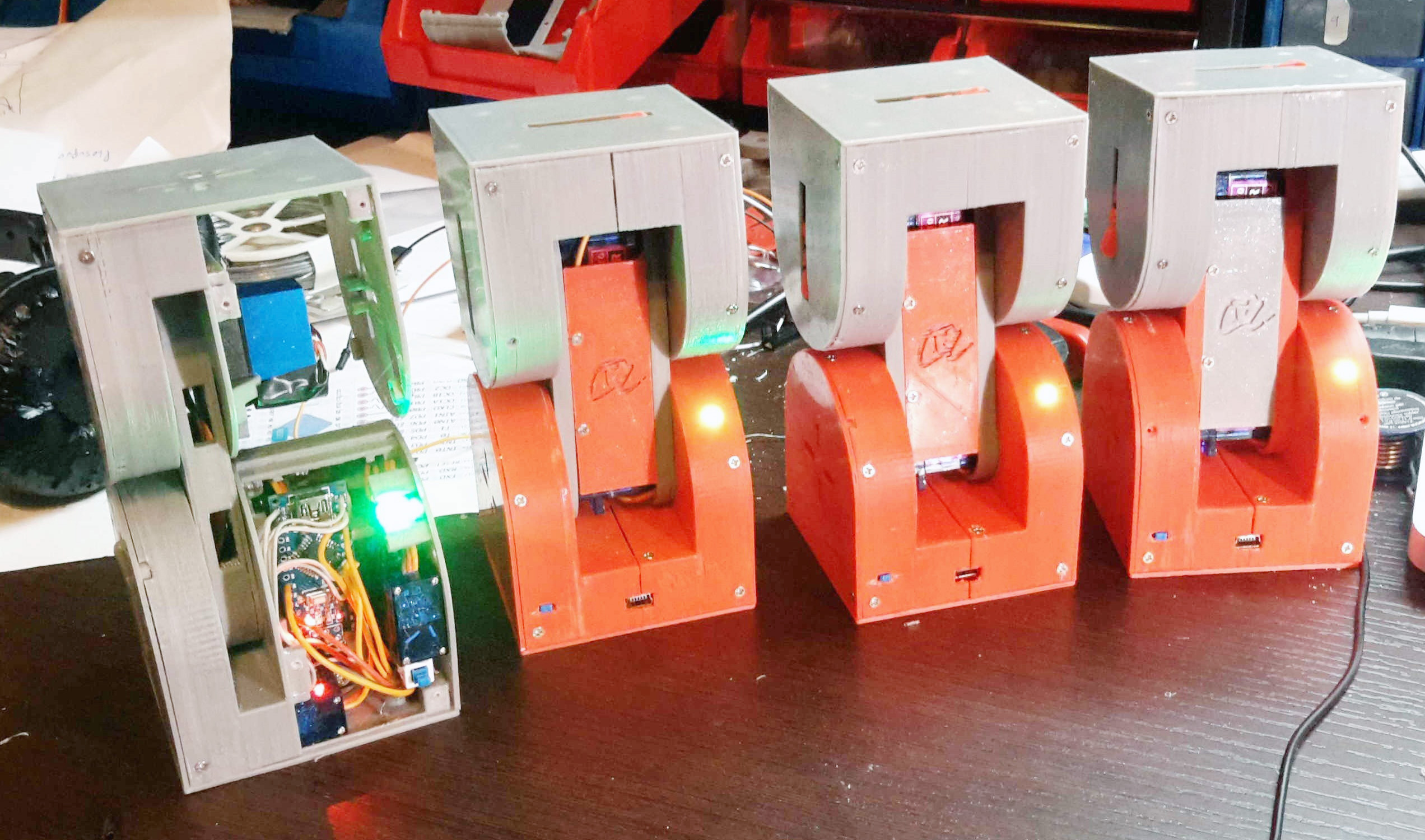
A robot to explore the unknown and automate tomorrow’s tasks and the ones after them needs to be extremely versatile. Ideally, it was capable of being any size, any shape, and any functionality, shapeless like water, flexible and smart. For his Hackaday Prize entry, [Alberto] is building such a modular, self-reconfiguring robot: Dtto.
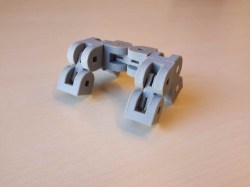
To achieve the highest possible reconfigurability, [Alberto’s] robot is designed to be the building block of a larger, mechanical organism. Inspired by the similar MTRAN III, individual robots feature two actuated hinges that give them flexibility and the ability to move on their own. A coupling mechanism on both ends of the robot allows the little crawlers to self-assemble in various configurations and carry out complex tasks together. They can chain together to form a snake, turn into a wheel and even become four (or more) legged walkers. With six coupling faces on each robot, that allow for connections in four orientations, virtually any topology is possible.
Each robot contains two strong servos for the hinges and three smaller ones for the coupling mechanism. Alignment magnets help the robots to index against each other before a latch locks them in place. The clever mechanism doubles as an ejector, so connections can be undone against the force of the alignment magnets. Most of the electronics, including an Arduino Nano, a Bluetooth and a NRF24L01+ module, are densely mounted inside one end of the robot, while the other end can be used to add additional features, such as a camera module, an accelerometer and more. The following video shows four Dtto robots in a snake configuration crawling through a tube.
A stock Arduino isn’t really known for its hi-fi audio generating abilities. For “serious” audio like sample playback, people usually add a shield with hardware to do the heavy lifting. Short of that, many projects limit themselves to constant-volume square waves, which is musically uninspiring, but it’s easy.
[Connor]’s volume-control scheme for the Arduino bridges the gap. He starts off with the tone library that makes those boring square waves, and adds dynamic volume control. The difference is easy to hear: in nature almost no sounds start and end instantaneously. Hit a gong and it rings, all the while getting quieter. That’s what [Connor]’s code lets you do with your Arduino and very little extra work on your part.
The code that accompanies the demo video (which is embedded below) is a good place to start playing around. The Gameboy/Mario sound, for instance, is as simple as playing two tones, and making the second one fade out. Nonetheless, it sounds great.
Behind the scenes, it uses Timer 0 at maximum speed to create the “analog” values (via PWM and the analogWrite() command) and Timer 1 to create the audio-rate square waves. That’s it, really, but that’s enough. A lot of beloved classic arcade games didn’t do much more.
While you can do significantly fancier things (like sample playback) with the same hardware, the volume-envelope-square-wave approach is easy to write code for. And if all you want is some simple, robotic-sounding sound effects for your robot, we really like this approach.
For Hackers, rapid prototyping is made easier using basic building blocks such as the Raspberry Pi, Arduino and the huge variety of add on shields for home brew projects. But we don’t see too many real world Industrial applications or machines built using these off-the-shelf electronics. [SlyScience] built The Green Machine – an industrial grade, automated spray painting device to help coat polycarbonate tubes consistently.
The Green Machine is essentially a linear drive that can move a spray gun across a spinning clear tube and coat it evenly with the desired color. These tubes are used as color filters – they slide over standard T5, T8 or T12 fluorescent lamps – and are used in advertising, special effects, films and similar applications. For almost 10 years prior to this machine, the task was done manually. The HPLV (high pressure, low volume) spray gun used for this process needed skilled hands to get consistent results. It was easy to ruin a tube and cleaning them was not possible. [SlyScience] figured things out on the go – teaching himself and figuring out all of the software and hardware pieces of the puzzle. The welded steel frame is about the only “custom” part in this build. Everything else is COTS. Check out the video of The Green Machine in action below, and if you have any tips to help improve the build, chime in with your comments.
Electrospinning is a fascinating process where a high voltage potential is applied between a conductive emitter nozzle and a collector screen. A polymer solution is then slowly dispensed from the nozzle. The repulsion of negative charges in the solution forces fine fibers emanate from the liquid. Those fibers are then rapidly accelerated towards the collector screen by the electric field while being stretched and thinned down to a few hundred nanometers in diameter. The large surface area of the fine fibers lets them dry during their flight towards the collector screen, where they build up to a fine, fabric-like material. We’ve noticed that electrospinning is hoped to enable fully automated manufacturing of wearable textiles in the future.
[Douglas Miller] already has experience cooking up small batches of microscopic fibers. He’s already made carbon nanotubes in his microwave. The next step is turning those nanotubes into materials and fabrics in alow-cost, open source electrospinning machine, his entry for the Hackaday Prize.
As always in fundamental research projects, a whole lot of parameters have to be tuned just right. To speed up the process of finding suitable values for the electric potential, dosing feed rate, emitter to collector plate distance, temperature, and humidity, [Douglas] build his machine with a CNC controlled vertical axis and syringe pump, that can dispense even the smallest amounts of a given solutions accurately. Temperature and humidity control will be added as the project progresses. A host software and GUI allows for easy control of all parameters and will also save and recall presets for different spinning solutions once everything has been dialed in. [Douglas] already ran a few tests, spraying saline solution from an old 3D printer nozzle, and we can soon expect first tests with polymer solutions from the better-suited syringe nozzles he installed.
To keep the build affordable and easy to reproduce for other makers, [Douglas] uses available materials and came up with a few design tricks that could also be applied to other projects. The belt-driven vertical axis is based on PVC pipes, on which a 3D-printed bushing block slides up and down, adjusting the distance between the nozzle and the collector plate. An acrylic door with a safety switch prevents the polymer spray from escaping from the spinning chamber. In the heart of the machine sits an Arduino Uno with a gShield, controlling the stepper motors and talking to the host computer. The 3D-printed syringe pump, a custom design, swings out from the side of the machine to allow for easy refilling. Submerged in mineral oil, which may have been chosen to reduce the risk of overheating and arcing, lies a half-wave series voltage multiplier, cranking up the voltage from an AC power supply to a maximum of 30 kV DC.
Last November, after [HomoFaciens]’ garbage-can CNC build, we laid down the gauntlet – build a working CNC from cardboard and paperclips. And now, not only does OP deliver with a working CNC plotter, he also plans to develop it into a self-replicating machine.
To be honest, we made the challenge with tongue firmly planted in cheek. After all, how could corrugated cardboard ever make a sufficiently stiff structure for the frame of a CNC machine? [HomoFaciens] worked around this by using the much less compliant chipboard – probably closest to what we’d call matboard here in the States. His templates for the machine are extremely well thought-out; the main frame is a torsion box design, and the ways and slides are intricate affairs. Non-cardboard parts include threaded rod for the lead screws, servos modified for continuous rotation, an Arduino, and the aforementioned paperclips, which find use in the user interface, limit switches, and in the extremely clever encoders for each axis. The video below shows highlights of the build and the results.
True, the machine can only move a pen about, and the precision is nothing to brag about. But it works, and it’s perfectly capable of teaching all the basics of CNC builds to a beginner, which is a key design goal. And it’s well-positioned to move to the next level and become a machine that can replicate itself. We’ll be watching this one very closely.
If you live in New England (like me) you know that the roads take a pounding in the winter. Combine this with haphazard maintenance and you get a recipe for biking disaster: bumpy, potholed roads that can send you flying over the handlebars. Project Dekoboko 凸凹 aims to help a little with this, by helping you map and avoid the bumpiest roads and could be a godsend in this area.
The 2015 Hackaday Prize entry from [Benjamin Shih], [Daniel Rojas], and [Maxim Lapis] is a device that clips onto your bike and maps how bumpy the ride is as you pedal around. It does this by measuring the vibration of the bike frame with an accelerometer. Combine this with a GPS log and you get a map of the quality of the roads that helps you plan a smooth ride, or which could help the city figure out which roads need fixing the most.
The project is currently on its third version, built around an Arduino, Adafruit Ultimate GPS Logger shield, and a protoboard that holds the accelerometer (an Analog ADXL345). The team has also set up a first version of their web site, which contains live data from a few trips around Berlin. This does show one of the issues they will need to figure out, though: the GPS data has them widely veering off the road, which means that the data was slightly off, or they were cycling through buildings on the Prinzenstrasse, including a house music club. I’ll assume that it was the GPS being inaccurate and not them stopping for a rave, but they will need to figure out ways to tie this data down to a specific street before they can start really analyzing it. Google Maps does offer a way to do this, but it is not always accurate, especially on city streets. Still, the project has made good progress and could be useful for those who are looking for a smooth ride around town.


 The project is currently on its third version, built around an Arduino,
