Posts with «stepper motor» label

New Project: Build a Two-Octave Laser Harp

I find laser harps fascinating. The first time I saw one was when I stumbled across a video of a guy using using lasers to play the theme song to Tetris. I thought it was the coolest thing ever, but I couldn’t justify the cost of buying one. Instead, I decided […]

Read more on MAKE

The post Build a Two-Octave Laser Harp appeared first on Make: DIY Projects, How-Tos, Electronics, Crafts and Ideas for Makers.

Robot on Rails for Time Lapse Photography

What do you get when you cross a photographer with an Arduino hacker? If the cross in question is [nukevoid], you wind up with a clever camera rail that can smoothly move with both shift and rotation capability. The impressive build uses an Arduino Pro Mini board and two stepper motors. One stepper moves the device on rails using some Delrin pulleys as wheels that roll on an extruded aluminum track. The other stepper rotates the camera platform.

The rotating platform is very cool. It’s a plastic disk with a GT2 motion belt affixed to the edge. The stepper motor has a matching pulley and can rotate the platform easily. The GT2 belt only goes around half of the disk, and presumably the software knows when to stop on either edge based on step counts. There’s even a support to steady the camera’s lens when in operation.

Some AA batteries provide power (so probably not going to run all day long without a battery change). Judging by the video, the whole set up is cat-resistant (although nothing is totally cat-proof). Photographers are an innovative bunch, and we’ve seen Android-powered rails before as well as spinning turntables.


Filed under: Arduino Hacks, robots hacks

Rotary Indexer gives Mill a 4th axis (sort of)

Rotary indexer’s are standard issue in most machine shops. These allow you to hold or chuck a work piece, and then a graduated handle lets you to rotate the workpiece. Useful when you want to drill or tap axial or radial features. A rack and pinion drive ensures that the workpiece does not move under machining load. Quite often, these indexers also have a manual lock to take care of gear backlash and play. Automating them is not too difficult either. You could use just a stepper motor (open loop) or servo+encoder (closed loop) to drive the turntable.

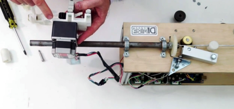
[smashedagainst] needed to drill six radial holes on a part. And he had to do it on 500 pieces for a total of 3000 holes. That was just for the first initial run, with more drilling likely in the future. The part in question was small and light weight. So instead of using a heavy duty, industrial grade unit, he built an all-electric rotary indexing jig using a stepper motor and an Arduino, giving him a sort of rotary 4th axis. His idea was to directly use the stepper motor to rotate the workpiece without any gearing, but he needed to build his own rig to do so.

His initial prototype used an Arduino Uno, which he swapped for a Pro Mini in the final version to save some space. The Arduino was connected to a Rugged Circuits motor driver. This was the only driver, out of the several that he tried that managed to hold the stepper motor with enough torque to prevent the workpiece from moving while drilling. The number of holes to be drilled is hard-coded in the Arduino, so all he needed was a single button. Each press of the button advanced the stepper motor through 60 degrees, giving him six, equally spaced holes. He used a NEMA-34 stepper motor, and that meant a beefy power supply. He scavenged a power supply from an old laser printer which conveniently had 24V DC as well as 5V outputs.

The next step was to work on the mechanical assembly. He machined an arbor that is attached to the shaft of the stepper motor. The face of the arbor is hexagonal and the workpiece wedges/locates over this. The motor assembly is fixed on one end of a base plate. The other end of the base plate has a clamping mechanism activated by a toggle clamp. It is also able to rotate (much like a live centre on a lathe). The workpiece is mated to the arbor, and the toggle clamp then locks the piece in place. During initial trials, some of the assembly fasteners worked loose, and there was some amount of chatter from the drill bit. He fixed these issues, and found it performed best when he set the spindle speed at 2400 rpm. Once he got it working, he was able to finish a hundred parts in under 2 hours. Drilling six holes in quick succession causes the part to get quite hot, so he first used some  pressurised air cooling. Later, he switched to a spray can based multi purpose penetrant lubricant. Watch his video of the indexing jig in action below.


Filed under: cnc hacks, tool hacks

Laser-Cut Clock Uses Planetary Gear

[wyojustin] was trying to think of projects he could do that would take advantage of some of the fabrication tech that’s become available to the average hobbyist. Even though he doesn’t have any particular interest in clocks, [wyojustin] discovered that he could learn a lot about the tools he has access to by building a clock.

[wyojustin] first made a clock based off of a design by [Brian Wagner] that we featured a while back. The clock uses an idler wheel to move the hour ring so it doesn’t need a separate hour hand. After he built his first design, [wyojustin] realized he could add a planetary gear that could move an hour hand as well. After a bit of trial and error with gear ratios, he landed on a design that worked.

The clock’s movement is a stepper motor that’s driven by an Arduino. Although [wyojustin] isn’t too happy with the appearance of his electronics, the drive setup seems to work pretty well. Check out [wyojustin]’s site to see the other clock builds he’s done (including a version with a second hand), and you can peruse all of his design files on GitHub.

Looking for more clock-building inspiration? Check out some other awesome clock builds we’ve featured before.


Filed under: Arduino Hacks, clock hacks

Versatile motion dolly for time lapse photography

This beautiful build is a motion dolly for making time-lapse videos. It is at a point where you could consider it complete. After all, the segments featured in the video after the break look marvelous. But [Scottpotamas] has a few additions planned and it sounds like it won’t belong before he accomplishes his goals.

The build is a linear rail on which the camera rides. In the image above you can see the stepper motor which moves the camera mounted at the far end of the rig. This is controlled by an Arduino. Currently the camera is responsible for timing the capture of the images, but [Scottpotamas] says the firmware is nearly ready to hand this responsiblity over to the Arduino. The system is modular, with a simple setting for the length of the track. This way he can swap out for a longer or shorter rail which only takes about five minutes. He also included support for a panning mount for the camera. It allows the control box can be programmed to keep the subject centered in the frame as the camera slides along the track.

[via Reddit]


Filed under: digital cameras hacks

Trying to use a light sensor to control a stepper motor

Am trying to control a stepper motor with a light sensor, when high do this and when low do that. But it dn't seem to be working please help.

read more

Raspberry Pi driven Polargraph exhibits high precision drawing ability

This polar graph draws some amazing shapes on a dry erase board. Part of that is due to the mounting brackets used for the two stepper motors and the stylus. But credit is also due for the code which takes velocity into account in order to plan for the next set of movements.

The Go language is used to translate data into step commands for the two motors. This stream of commands is fed over a serial connection between the RPi board and an Arduino. The Arduino simply pushes the steps to the motor controllers. The inclusion of the RPi provides the horsepower needed to make such smooth designs. This is explained in the second half of [Brandon Green's] post. The technique uses constant acceleration, speed, and deceleration for most cases which prevents any kind of oscillation in the hanging stylus. But there are also contingencies used when there is not enough room to accelerate or decelerate smoothly.

You can catch a very short clip of the hardware drawing a tight spiral in the video embedded after the break.


Filed under: Raspberry Pi
Hack a Day 16 Nov 17:30

Arduino based Milling Machine

This is a working model of an Arduino based Milling Machine created using FischerTechnik. For those of you who are unaware of FischerTechnik, it is similar to the LEGOTM Building Blocks.

A group of four Mechanical Engineering students at the Delft University of Technology (Netherlands) created this project as part of their Mechatronics class in their Second year of Bachelor of Sciences (B.Sc.) Program.

Laurens Valk, one of the creators, explains the essence of Arduino in the project:

“The system uses the Adafruit motor shield to run two stepper motors, and the Sparkfun EasyDriver for the third stepper motor. The Arduino runs code that listens to Matlab commands over USB. We expanded that code a little to make it possible to add the third stepper motor and some other commands. Most of the actual code was programmed in Matlab, with the Arduino as the interface between computer and motors/sensors.”

We had a little chat with Laurens. Here is the excerpt:


When did you first hear about Arduino, and when did you first start using it?
I’ve seen a lot of Arduino projects over the years, but this was the first time we used it in a project. Personally, I usually build robots with MINDSTORMS NXT, but this felt like a good opportunity to combine mechanical work (the printer hardware) with real electronics (Arduino).
How did you end up making a Milling Machine/ 3D Printer for your project?

We chose to come up with our own design challenge and decided not to do the standard exercise. Initially we thought about making a (2D) plotter or scanner. Then quickly we started thinking about the same things, except in 3D. One of the projects that inspired us was the LEGO Milling Machine by Arthur Sacek. Both a scanner and printer would still be doable in 3D, but the time was limited, so we settled with the printer idea.

All construction had to be done in one workweek for logistical reasons. To make sure we were able to finish in time, we prepared much of the electronics and software outside the lab. We finished just in time, but unfortunately we could do only one complete print before we had to take it apart. Not surprisingly, it was very exciting to wait for the result of the one and only complete test run. We couldn’t see the result until we used the vacuum cleaner to remove the dust.

Here is a video showing the working of this machine. [And the Vacuum Cleaner Laurens is talking about]:

This gives an Insight into the many feats that an Arduino can accomplish.


A closer looks helps you build your own DiWire Bender

Whether or not you’re actually going to build this CNC wire bender, we think you’ll love getting a closer look at how it’s put together. The team over at PENSA got such a strong response from a look at the original machine that they decided to film a video (embedded after the break) showing how the thing was put together. They’ve also posted a repository with code, bom, etc.

In the image above [Marco] shows off the portion that actually does the bending. It’s designed to mount on the pipe through which the straightened wire is fed. The 3d printed mounting bracket really makes this a lot easier. The assembly provides a place to attach the solenoid which moves a bearing in and out of position. That bearing presses against the wire to do the bending, but must be moved from one side of the wire to the other depending on the direction of the next bend. This is a lot easier to understand after watching the demo video which is also embedded after the break.


Filed under: cnc hacks
Hack a Day 21 Jun 12:01