Posts with «software» label

Stuff

A customer recently requested a two-faced Wise Clock, basically two displays back-to-back connected to the same Wise Clock board, and showing the same thing (in the same time) on both sides. This would be another "Kandinsky" clock (see this post for pictures of the original; name coined by Wyolum, I believe).

To include this feature in the current software was not trivial. The main idea was to define a new macro (WANT_TWO_FACE) and play with it around existing calls to HT1632 functions. This was the idea. The actual implementation is quite messy and spreads over 18 or so (mostly the "app") files. In any case, I only beta-tested it with 2 displays and works in all modes except "Big" (I didn't bother to investigate yet).

Here are a few photos.


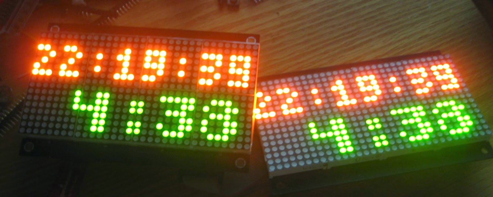
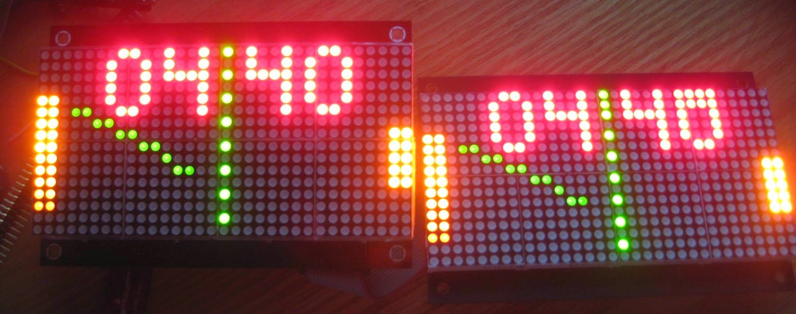
(The second display has a defect, hence the crooked last 0.)

Next round of testing should cover the 4-display 2-faced clock, that is, 2 displays on each side, like a double dual Wise Clock (I know, it's confusing. I will probably ask permission to rename it "Single Kandinsky Wise Clock" and "Double Kandinsky Wise Clock" since I am running out of attributes. Just kidding.)

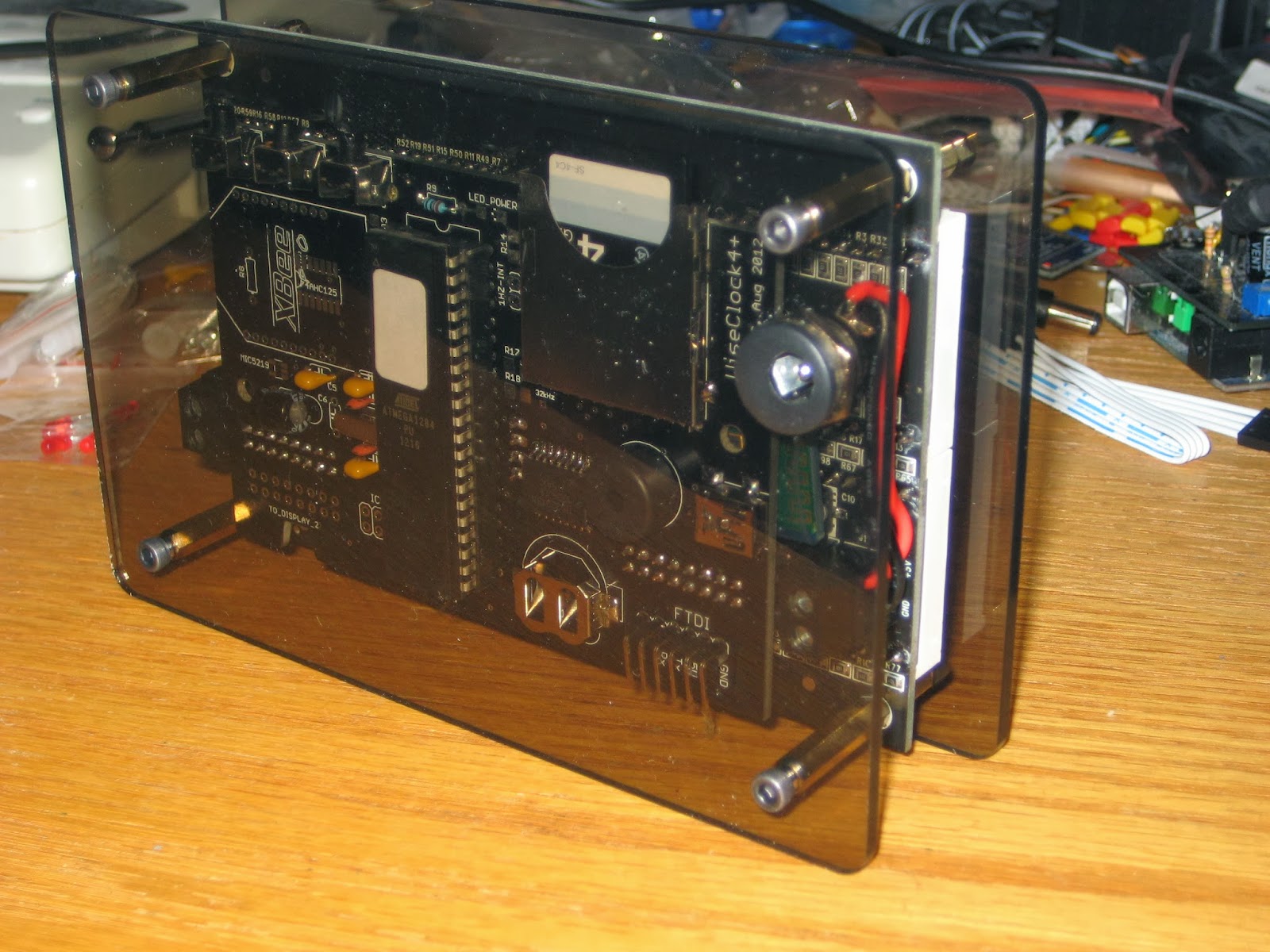
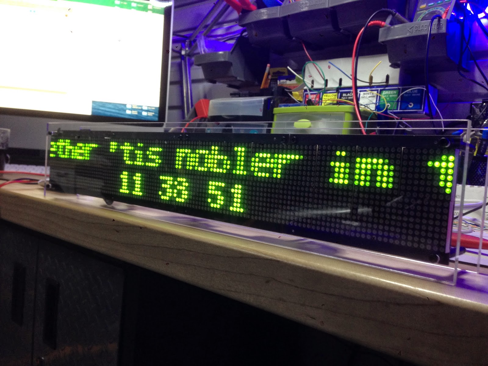
On a different front, my friend Nick built a 4-display Wise Clock 4 and sent me this photo (plus a set of laser-cut plates to build one myself too; thanks again Nick). Apparently, the software for the 4-display clock has some bugs, so expect soon a new code release (which will include the "two-faced" feature as well).


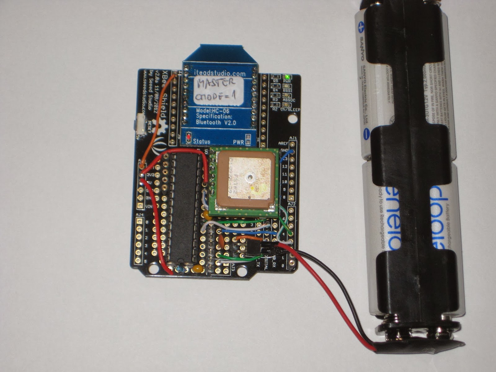
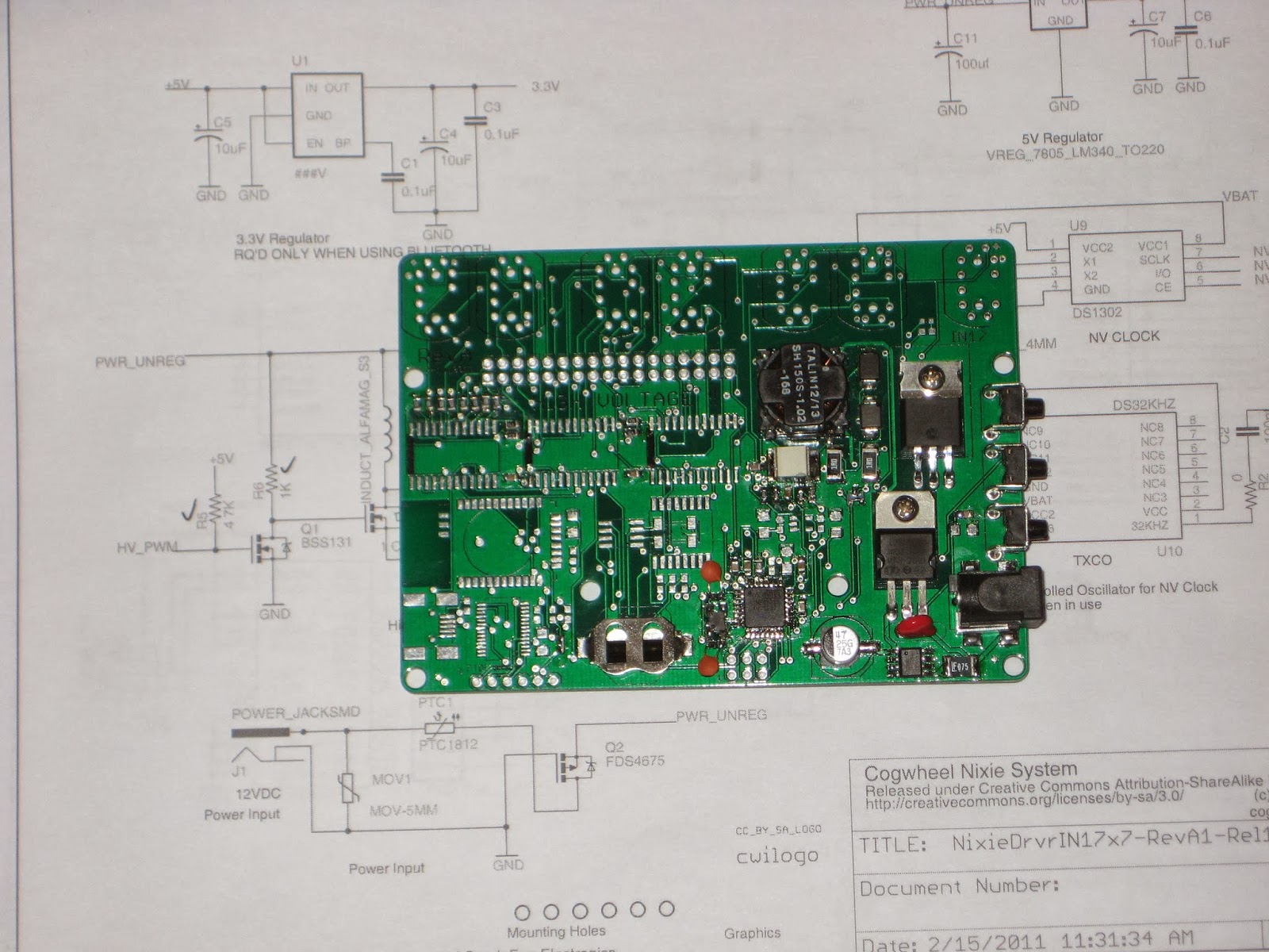
And lastly, I found this board on ebay. No, I did not buy it (and I am not going to). Just look carefully at the photo and think how you would encase it, with a knob inserted on the pot's shaft..


"Method and apparatus" for mass-synchronizing clocks

Most of my clocks (e.g. this Nixie clock, this other Nixie clock, BookClock, and obviously Wise Clock 4) have on-board Bluetooth, intended mainly for setting up the time, without the need for buttons (the lousy holes I would drill may negatively impact the aesthetics).
To set up the time, simply send the command TIME=hh:mm:ss, where "hh", "mm", "ss" are the hours, the minutes and the seconds, respectively.

Setting up multiple clocks is a tedious process: pair your Android tablet with one at a time, then (from BlueTerm) send the command that includes the correct time. Then repeat for each clock.

What if you could broadcast the TIME=... command? And that command to include the most accurate time, acquired from GPS? This is what this post is about. Now you have the "method".

Next, to the "apparatus". It consists essentially of 3 parts: GPS receiver, microcontroller and Bluetooth master module. Putting them together is trivial, since both GPS receiver and Bluetooth module communicate through serial ports.


I used an old (now discontinued at the major online stores, but still available on ebay) Fastrax UP-501 GPS module I already had laying around. But any GPS receiver should work as well, including the Adafruit Ultimate GPS Breakout.

The "Bluetooth master module" is a re-programmed HC-05 (see the datasheet) as master, with CMODE=1 (for broadcasting).

The sketch, presented below, uses SoftwareSerial library to communicate with the GPS module (Rx on D3, Tx on D4) and TinyGPS library to extract the time from the NMEA sentence. The BTBee module is connected to the hardware serial port (D0, D1).


#include "TinyGPS.h"
#include "SoftwareSerial.h"
SoftwareSerial GPSSerial(4, 3);

// GPS Fatrax UP501, connected as follows:
// - power pin to 3.3V
// - ground pin to ground
// - VBAT pin to 3.3V if no battery is used
// - TX pin to D4
// - RX pin to D3 through a voltage divider (2 resistors, 10k + 4k7)

#define _DEBUG_  true

// commands  for GPS module;
#define PMTK_SET_NMEA_UPDATE_1HZ  "$PMTK220,1000*1F"
#define PMTK_SET_NMEA_UPDATE_5HZ  "$PMTK220,200*2C"
#define PMTK_SET_NMEA_UPDATE_10HZ "$PMTK220,100*2F"

// turn on only the second sentence (GPRMC)
#define PMTK_SET_NMEA_OUTPUT_RMCONLY "$PMTK314,0,1,0,0,0,0,0,0,0,0,0,0,0,0,0,0,0,0,0*29"
// turn on ALL THE DATA
#define PMTK_SET_NMEA_OUTPUT_ALLDATA "$PMTK314,1,1,1,1,1,1,0,0,0,0,0,0,0,0,0,0,0,0,0*28"

// MTK command datasheet at http://www.hhhh.org/wiml/proj/nmeaxor.html

TinyGPS gps;

void setup()  
{
  // default baud rate for BTBee (on hardware serial);
  Serial.begin(9600);

  // default baud rate for UT501 (on software serial);
  GPSSerial.begin(9600);
  
  // turn on all the available data (for 9600 baud you'll want 1Hz rate);
  GPSSerial.println(PMTK_SET_NMEA_OUTPUT_ALLDATA);
  
  // set update rate to 1Hz
  GPSSerial.println(PMTK_SET_NMEA_UPDATE_1HZ);

#ifdef _DEBUG_
  Serial.println("ready for reading GPS...");
#endif
}

void loop()
{
  acquireTimeFromGPS();
  delay(5000);
}

void acquireTimeFromGPS()
{
  unsigned long age;
  int Year;
  byte Month, Day, Hour, Minute, Second, Hundredths;

  if (feedgps())
  {
#ifdef _DEBUG_
    Serial.println("GPS feed acquired...");
#endif
    gps.crack_datetime(&Year, &Month, &Day, &Hour, &Minute, &Second, &Hundredths, &age);
    char buf[20] = {0};
    sprintf(buf, "TIME=%02d:%02d:%02d", Hour, Minute, Second+1);
    Serial.println(buf);
  }
}

bool feedgps()
{
  while (GPSSerial.available())
  {
    char c = GPSSerial.read();
#ifdef _DEBUG_
    Serial.print(c);
#endif

    if (gps.encode(c))
      return true;
  }
  return false;
}

As protoboard I used the XBee Shield from seeedstudio because it had a socket for my BTBee (plus 3V3 regulator) and also ample space for processor and GPS. (It could even fit in a Altoids tin if  the GPS receiver is soldered directly to the board, without headers.)

Future improvements should include a couple of status LEDs, one to show that the data was being acquired from GPS, another to indicate that the "TIME" command was successfully built and broadcast. Similarly but more expensively, a small OLED screen could be used to display the activity.
On the software side, the time, which comes as UTC in the NMEA sentence, should be adjusted to the current time zone, probably based on the longitude.

Interrupt-based sketch for Adafruit coin acceptor

Some time ago I bought this coin acceptor. Programming it to accept 4 different types of coins is convoluted, but quite ingenious, and works exactly as the spec sheet indicates, without glitches. Surprising for such a complex task, considering that the user interface consists of 3 buttons and two 7-segment LED displays.
After setting it up, the mechanism identifies each coin type reliably, even providing user-friendly feedback (showing on the LED display the number of impulses sent over the COIN/white wire), very helpful for debugging.

Now onto actually using it. Adafruit's graciously provided the "Piggy bank" sample project,  including the Arduino sketch as well. The sketch however, counts the impulses simply in the loop() function. That may work fine in that particular setup, with just the coin acceptor (1 coin type nonetheless) and the LCD display. If you want to add more hardware (printer, buttons, bluetooth, SD card, LEDs etc), you need a smarter, hardware-independent, way to count the impulses from the coin acceptor. Naturally, that involves interrupts.

I present below a snapshot of my interrupt-based sketch, tested in a more complex hardware setup. The COIN wire is connected to D2, attached to interrupt INT0. Function coinISR() gets called for each impulse from the coin acceptor. A coin is recognized when a train of expected number of impulses is received in a sequence.


#define COIN_PIN 2

void setup()
{
  // Debugging output
  Serial.begin(9600);

  // set up the LCD's number of rows and columns:
  lcd.begin(16, 2);

  Serial.println("Ready...");
  
  pinMode(COIN_PIN, INPUT);
  attachInterrupt(0, coinISR, RISING);  // COIN wire connected to D2;
}


// total amount of money collected;
float money = 0.0;

// gets incremented by the ISR;
// gets reset when coin was recognized (after train of pulses ends);
volatile int pulses = 0;
volatile long timeLastPulse = 0;


// executed for every pulse;
void coinISR()
{
  pulses++;
  timeLastPulse = millis();
}


void loop()
{
  lcd.setCursor(0,0);
  lcd.print("Please put coins");
  lcd.setCursor(0,1);
  lcd.print("PAID $");
  lcd.print(money);

  long timeFromLastPulse = millis() - timeLastPulse;
  if (pulses > 0 && timeFromLastPulse > 200)
  {
    // sequence of pulses stopped; determine the coin type;
    if (pulses == 2)
    {
      Serial.println("Received dime (2 pulses)");
      money += .1;
    }
    else if (pulses == 5)
    {
      Serial.println("Received quarter (5 pulses)");
      money += .25;
    }
    else if (pulses == 10)
    {
      Serial.println("Received looney (10 pulses)");
      money += 1.0;
    }
    else if (pulses == 15)
    {
      Serial.println("Received tooney (15 pulses)");
      money += 2.0;
    }
    else
    {
      Serial.print("Unknown coin: ");
      Serial.print(pulses);
      Serial.println(" pulses");
    }

    pulses = 0;
  }
}


Wise time with Arduino 31 Jan 18:45
software  

Easily test and experiment with GSM modules using AT Command Tester

Introduction

Working with GSM modules and by extension Arduino GSM shields can either be a lot of fun or bring on a migraine. This is usually due to the quality of module, conditions placed on the end user by the network, reception, power supply and more.

Furthermore we have learned after several years that even after following our detailed and tested tutorials, people are having trouble understanding why their GSM shield isn’t behaving. With this in mind we’re very happy to have learned about a free online tool that can be used to test almost every parameter of a GSM module with ease – AT Command Tester. This software is a Java application that runs in a web browser, and communicates with a GSM module via an available serial port.

Initial Setup

It’s simple, just visit http://m2msupport.net/m2msupport/module-tester/ with any web browser that can run Java. You may need to alter the Java security settings down to medium. Windows users can find this in Control Panel> All Control Panel Items  > Java – for example:

Once the security settings have been changed, just visit the URL, click ‘accept’ and ‘run’ in the next dialogue box that will appear, for example:

And after a moment, the software will appear:

Once you’re able to run the AT Command Tester software, the next step is to physically connect the hardware. If you’re just using a bare GSM module, a USB-serial adaptor can be used for easy connection to the PC. For Arduino GSM shield users, you can use the Arduino as a bridge between the shield and PC, however if your GSM shield uses pins other than D0/D1 for serial data transmission (such as our SIM900 shield) then you’ll need to upload a small sketch to bridge the software and hardware serial ports, for example:

//Serial Relay – Arduino will patch a serial link between the computer and the GPRS Shield
//at 19200 bps 8-N-1 Computer is connected to Hardware UART
//GPRS Shield is connected to the Software UART

#include <SoftwareSerial.h>

SoftwareSerial mySerial(7,8); // change these paramters depending on your Arduino GSM Shield

void setup()
{
  Serial.begin(19200);
  //Serial.println(“Begin”);
  mySerial.begin(19200);

}

void loop()
{
  if (mySerial.available())
    Serial.write(mySerial.read());
  if (Serial.available())
    mySerial.write(Serial.read());
}

Using the software

Once you have the hardware connected and the Arduino running the required sketch, run the software – then click “Find ports” to select the requried COM: port, set the correct data speed and click “Connect”. After a moment the software will interrogate the GSM module and report its findings in the yellow log area:

 As you can see on the left of the image above, there is a plethora of options and functions you can run on the module. By selecting the manufacturer of your GSM module form the list, a more appropriate set of functions for your module is displayed.

When you click a function, the AT command sent to the module and its response is shown in the log window – and thus the magic of this software. You can simply throw any command at the module and await the response, much easier than looking up the commands and fighting with terminal software. You can also send AT commands in batches, experiment with GPRS data, FTP, and the GPS if your module has one.

To give you a quick overview of what is possible, we’ve made this video which captures us running a few commands on a SIM900-based Arduino shield. If possible, view it in 720p.

Conclusion

Kudos to the people from the M2Msupport website for bringing us this great (and free) tool. It works – so we’re happy to recommend it. And if you enjoyed this article, or want to introduce someone else to the interesting world of Arduino – check out my book (now in a third printing!) “Arduino Workshop”.

Have fun and keep checking into tronixstuff.com. Why not follow things on twitterGoogle+, subscribe  for email updates or RSS using the links on the right-hand column, or join our forum – dedicated to the projects and related items on this website. Sign up – it’s free, helpful to each other –  and we can all learn something.

The post Easily test and experiment with GSM modules using AT Command Tester appeared first on tronixstuff.

Easily test and experiment with GSM modules using AT Command Tester

Introduction

Working with GSM modules and by extension Arduino GSM shields can either be a lot of fun or bring on a migraine. This is usually due to the quality of module, conditions placed on the end user by the network, reception, power supply and more.

Furthermore we have learned after several years that even after following our detailed and tested tutorials, people are having trouble understanding why their GSM shield isn’t behaving. With this in mind we’re very happy to have learned about a free online tool that can be used to test almost every parameter of a GSM module with ease – AT Command Tester. This software is a Java application that runs in a web browser, and communicates with a GSM module via an available serial port.

Initial Setup

It’s simple, just visit http://m2msupport.net/m2msupport/module-tester/ with any web browser that can run Java. You may need to alter the Java security settings down to medium. Windows users can find this in Control Panel> All Control Panel Items  > Java – for example:

Once the security settings have been changed, just visit the URL, click ‘accept’ and ‘run’ in the next dialogue box that will appear, for example:

And after a moment, the software will appear:

Once you’re able to run the AT Command Tester software, the next step is to physically connect the hardware. If you’re just using a bare GSM module, a USB-serial adaptor can be used for easy connection to the PC. For Arduino GSM shield users, you can use the Arduino as a bridge between the shield and PC, however if your GSM shield uses pins other than D0/D1 for serial data transmission (such as our SIM900 shield) then you’ll need to upload a small sketch to bridge the software and hardware serial ports, for example:

//Serial Relay – Arduino will patch a serial link between the computer and the GPRS Shield
//at 19200 bps 8-N-1 Computer is connected to Hardware UART
//GPRS Shield is connected to the Software UART

#include <SoftwareSerial.h>

SoftwareSerial mySerial(7,8); // change these paramters depending on your Arduino GSM Shield

void setup()
{
  Serial.begin(19200);
  //Serial.println(“Begin”);
  mySerial.begin(19200);

}

void loop()
{
  if (mySerial.available())
    Serial.write(mySerial.read());
  if (Serial.available())
    mySerial.write(Serial.read());
}

Using the software

Once you have the hardware connected and the Arduino running the required sketch, run the software – then click “Find ports” to select the requried COM: port, set the correct data speed and click “Connect”. After a moment the software will interrogate the GSM module and report its findings in the yellow log area:

 As you can see on the left of the image above, there is a plethora of options and functions you can run on the module. By selecting the manufacturer of your GSM module form the list, a more appropriate set of functions for your module is displayed.

When you click a function, the AT command sent to the module and its response is shown in the log window – and thus the magic of this software. You can simply throw any command at the module and await the response, much easier than looking up the commands and fighting with terminal software. You can also send AT commands in batches, experiment with GPRS data, FTP, and the GPS if your module has one.

To give you a quick overview of what is possible, we’ve made this video which captures us running a few commands on a SIM900-based Arduino shield. If possible, view it in 720p.

Conclusion

Kudos to the people from the M2Msupport website for bringing us this great (and free) tool. It works – so we’re happy to recommend it. And if you enjoyed this article, or want to introduce someone else to the interesting world of Arduino – check out my book (now in a third printing!) “Arduino Workshop”.

Have fun and keep checking into tronixstuff.com. Why not follow things on twitterGoogle+, subscribe  for email updates or RSS using the links on the right-hand column, or join our forum – dedicated to the projects and related items on this website. Sign up – it’s free, helpful to each other –  and we can all learn something.

My first impression on Cogwheel Nixie clock

Many months ago I bought, attracted by the clearance price, the PCB for the "Nixie Driver Board Rev A" from "Cogwheel circuit works" store. I was hoping that, with all documentation in place, I would be able to build it on my own, considering it's controlled by an ATmega328 and the software was available, though not the source code.

First thing to note is that the board uses mostly SMDs. If anything went wrong (and there was a high chance, since the PCB was already described as a "mistake the board house made"), the board would become a coaster.

The schematic includes some exotic components, like the HV513 Nixie driver, not offered by digikey. Others are the DS1302 RTC and the optional DS32KHZ oscillator for RTC, which I heard of for the first time. But thanks to the detailed BOM, gathering the components was relatively (some of them are already discontinued, for example) easy.

High voltage for the Nixie tubes is generated by a hardware PWM under software control. So, like the Ice Tube Clock, in order to measure the high voltage and make sure the HV circuitry works, some software must be uploaded onto the processor. I expected the released software to do that. Unfortunately, the highest voltage I saw was under 9V.


After some digging (and learning in the process), I ended up with this simple sketch, adapted from Satashnik Nixie clock, which generates a stable 190V. I know, I was surprised too :)

#include "Arduino.h"

#define DDRHVPUMP  DDRB
#define BV2(a,b) (_BV(a)|_BV(b))
#define BV6(a,b,c,d,e,f) (_BV(a)|_BV(b)|_BV(c)|_BV(d)|_BV(e)|_BV(f))
#define VOLTAGE_WASTE   370                     //!< ~180V
#define VOLTAGE_SAVE    355                     //!< ~170V

volatile uint16_t voltage; 
static volatile uint16_t voltage_setpoint = VOLTAGE_WASTE;
static const uint16_t ocr1a_reload = 60;

void pump_init()
{
    // set fast pwm mode
    // COM1A1:0 = 10, clear oc1a on compare match, set at top
    // COM1B1:0 = 00, normal port operation
    // no FOC
    // WGM11:10 (WGM = Fast PWM, TOP=ICR1: 1110) = 11
    TCCR1A = BV2(COM1A1, WGM11);
    TCCR1B = BV2(WGM13,  WGM12);
    OCR1A = ocr1a_reload; 
    ICR1 = 170;
    TCCR1B |= _BV(CS10); // clk/1 (16MHz)
    DDRHVPUMP |= BV2(1,2);
}

void adc_init()
{
    voltage = 0;
    // PORTA.6 is the feedback input, AREF = AREF pin
    ADMUX = 6;  
    // ADC enable, autotrigger, interrupt enable, prescaler = 111 (divide by 32)
    ADCSRA = BV6(ADEN, ADATE, ADIE, ADPS2, ADPS1, ADPS0); 
    ADCSRA |= _BV(ADSC); 
}

/// Start voltage booster
void voltage_start()
{
    adc_init();
    pump_init();
}

ISR(ADC_vect)
{
    voltage = (voltage + ADC) / 2;
    if (voltage < voltage_setpoint) {
        OCR1A = ocr1a_reload;
    } else {
        OCR1A = 0;
    }
}

void setup()
{
    sei();
    voltage_start();        // start HV generation    
}

void loop()
{
  // clock functionality in here;
}

The next big step is to write the software to drive the tubes and actually show the time, which is essentially re-writing the Cogwheel Nixie clock code (or at least the basic functionality) from scratch. Then open source it. Any help would be appreciated :)

Alarm clock app for iPhone

My young friend Rami left his comfortable and safe permanent job with a solid consulting company to start his own business, mainly writing apps for mobile devices. His first app is "Deep Sleep Alarm" for iPhone, available for download in the App Store.

The app is free, with nice graphics and useful functionality, basically making sure you are not "cheating" when  waking up :)  Please give it a try.


He is currently working on the Android version.
Rami, keep up the great work!

Review – “Ardublock” graphical programming for Arduino

Introduction

After helping many people get started with the world of Arduino and electronics,  we still find a small percentage of people who are turned off by the concept of programming or have trouble breaking larger tasks into smaller ones with regards to writing algorithms for their code/sketch.

So after being introduced to a new graphical programming tool called “Ardublock“, we were excited about the possibilities wanted to share it with our readers. Ardublock provides a truly graphical and non-coding solution to controlling an Arduino, that is an open-source product and thus free to download and try for yourself.

Installation

Ardublock is a Java application that runs from inside the Arduino IDE, which can be downloaded from here. It’s only one file, that needs to be placed in a new folder in the Arduino IDE. The folder names must be the same as shown below:

Once you’ve copied the file, simply open the Arduino IDE and select Ardublock from the Tools menu:

From which point a new window appears – the Ardublock “development environment”:

 Using Ardublock

It’s quite simple – you simply select the required function from the menu on the left and drag it into the large area on the right. For a quick example where we blink the onboard LED on and off – watch the following video:


The following image is the screen capture of the program from the video:

As you can see the “blocks” just fit together, and parameters can be changed with the right mouse button. After a few moments experimenting with the Ardublock software you will have the hang of it in no time at all.

And thus you can demonstrate it to other people and show them how easy it is. And there is much more than just digital output controls, all the functions you’re used to including I2C, variables, constants, servos, tone and more are available.

The only technical thing you need to demonstrate is that the Arduino IDE needs to stay open in the background – as once you have finished creating your program, Ardublock creates the required real Arduino sketch back in the IDE and uploads it to the board.

This is also a neat function – the user can then compare their Ardublock program against the actual sketch, and hopefully after a short duration the user will have the confidence to move on with normal coding.

Conclusion

Ardublock provides a very simple method of controlling an Arduino, and makes a great starting point for teaching the coding-averse, very young people or the cognitively-challenged. It’s open source, integrates well with the official IDE and works as described – so give it a go.

And if you enjoyed this review, or want to introduce someone else to the interesting world of Arduino – check out my book (now in a third printing!) “Arduino Workshop” from No Starch Press.

In the meanwhile have fun and keep checking into tronixstuff.com. Why not follow things on twitterGoogle+, subscribe  for email updates or RSS using the links on the right-hand column? And join our friendly Google Group – dedicated to the projects and related items on this website. Sign up – it’s free, helpful to each other –  and we can all learn something.

The post Review – “Ardublock” graphical programming for Arduino appeared first on tronixstuff.

Play Tetris on Wise Clock 4

No kidding.
I was looking for a suitable application to demo with Wise Clock 4 placed vertically (that is, standing on its shortest side), when I found this hackaday post about Tetris on a LED matrix. The code, already written for Arduino, clean and easy to understand (kudos to Jianan), was a breeze to port. I only had to change a few functions (display, user buttons), comment out a few more (sound, text etc) and downsize from 7 colors to just 3.
Commands come from Bluetooth terminal ("BlueTerm" app on Android), basically replacing the buttons with letters (U, R, L, D; you got the idea).


The Wise Clock 4 vertical stand is possible thanks to the enclosure-mounted power jack, wired to the display's screw terminals, as shown in the photo below (that also captures a part of my messy desk).


(This is a typical example of how one thing leads to another. I don't usually play games, but when I do, I use my implementations. "Time well wasted", as the saying goes.)

New release of Wise Clock 4 software

Some of the latest software features have already been introduced (see this post). Since then, a few bugs have been fixed (again, thanks Mike!), the code was streamlined even more, and some apps (Countdown, Score, Stopwatch, Quote) have been expanded and improved.

Below is a list of the most recent code changes:
  • added PWRON setup option to select app to run when the clock starts up;
  • compilations options (add/remove features) moved to file "UserConf.h". That is:
- Instead of editing WiseClock.cpp to select applications to build, edit "UserConf.h".
- Instead of editing WiseClockVer.h to select WiseClock 3 or 4, edit "UserConf.h".
- Instead of editing HT1632.h to select the number of displays, edit "UserConf.h".
  • on dual display, Countdown includes days as well, in the format DD:HH:MM:SS;
  • Countdown shows the correct amount of time left even if power was down for a while (this is done by saving the end time in eeprom); for this feature, the PWRON must be set to "CNTDWN";
  • similar to Countdown, app Score has been extended to "remember" the numbers even after the power was out for a while; in either case, the respective app must be selected in PWRON;
  • ability to display quotes randomly, if the user selects "RND" in app Quote;
  • on dual display, Stopwatch is now using regular-size font (still using tiny font on single display);
  • Stopwatch has a new mode, "Conventional", in addition to the previous one (called "Rattrapante"); the conventional mode accumulates the time passed between consecutive presses of the start/stop button, as a mechanical chronometer would do; "rattrapante" mode shows the amount of time passed from the moment it was first started, regardless of how many times the chronometer was stopped;
  • on dual display, with "Font+" selected, Score and Stopwatch are using big font and no longer show the current time on the bottom line (they show as before with "Font-" selected); 

One of the challenges in writing complex code for embedded systems is the compromise between following an Object Oriented approach and trying to minimize the amount of RAM at runtime. Let me elaborate a bit. Each C++ object, once created (at runtime), used or not, takes some RAM, storing data members and the vtable (when using virtual functions). Wise Clock software is trying to follow an OO design. Each App class is derived from an abstract base class. The base class defines 2 pure virtual functions (init and run), which must be implemented by every App class.
At runtime, each app is created as a static object. Therefore, if 12 apps are declared (through the use of ifdefs in UserConf.h), 12 objects will be created in RAM, each one storing its own data and its own vtable. That's a pretty big price to pay in the world of embedded systems with little RAM space (just a guess, based on my very limited experience).

A non OO approach would create and use variables only for the app that is in current use, as the code is being executed. Although this solution would use less RAM, the current complexity would make the code unmanageable.

So back to the compromise, how does one solve it? (This is not a rhetorical question.)