Posts with «peripherals hacks» label

Tiny Morse Code USB Keyboard

We’ve featured quite a few of [mitxela]’s projects here in the past, and many of them have the propensity to be labelled “smallest”. His Morse Code USB Keyboard Mk II adds to that list. It’s a Saturday afternoon project, with a few parts slapped onto a piece of perf-board, that allows using a Morse key as a USB keyboard. This project isn’t new or fresh, but we stumbled across it while trying to figure out a use for a Morse key lying in the author’s bin of parts. You can practise transmitting, by reading text and typing it out on the key, and then look it up on your computer to see if you made any mistakes. Or you can practise receiving, by asking a friend to punch it out for you. Either way, it’s a great way to hone your skills and prepare for your radio operators license exam.

The project is a follow up to his earlier one where he hooked up the Morse key via a RS-232 — USB converter directly to a computer and let the code do all the work. That turned out to be a very resource hungry, impractical project and made him do it right the next time around. The hardware is dead simple. An ATtiny85, a piezo buzzer, some decoupling capacitors, and a few resistors and zeners to allow a safe USB interface. The design accommodates a straight key, but there is one spare pin left over in the ATtiny to allow for iambic or sideswiper keys too. There is no speed adjustment, which is hardcoded at the moment. That isn’t very user friendly, and [mitxela] suggests adding a speed potentiometer to that last remaining pin on the ATtiny. This would prevent use of iambic/sideswiper keys. Or, you could use the RST pin on the ATtiny as a (weak) IO. The RST pin can read analog values between 5V and 2.5V, and will reset when voltage falls below 2.2V. Or just use another microcontroller as a last resort.

For the USB interface, [mitxela] is using the V-USB library after wasting some time trying to reinvent the wheel. And since this is designed to work as a HID, there are no drivers required – plug it in, and the OS detects it as a keyboard. He’s borrowed code from the EasyLogger project to use the internal oscillator and help free up the IO pins. And to detect the characters being typed, his code uses a long string of compare statements instead of a dictionary lookup. Writing that code was tedious, but it makes the identification quicker, since most characters can be identified in less that five comparisons (one dit = E, two dits = I, three dits = S and so on). This “tree” makes it easier to figure it out.

If you’d like to look up some of his other “tiny” projects, check out The smallest MIDI synthesizer, Smallest MIDI synth, again! and the ATtiny MIDI plug synth.


Filed under: peripherals hacks

MalDuino — Open Source BadUSB

MalDuino is an Arduino-powered USB device which emulates a keyboard and has keystroke injection capabilities. It’s still in crowdfunding stage, but has already been fully backed, so we anticipate full production soon. In essence, it implements BadUSB attacks much like the widely known, having appeared on Mr. Robot, USB Rubber Ducky.

It’s like an advanced version of HID tricks to drop malicious files which we previously reported. Once plugged in, MalDuino acts as a keyboard, executing previous configured key sequences at very fast speeds. This is mostly used by IT security professionals to hack into local computers, just by plugging in the unsuspicious USB ‘Pen’.

[Seytonic], the maker of MalDuino, says its objective is it to be a cheaper, fully open source alternative with the big advantage that it can be programmed straight from the Arduino IDE. It’s based on ATmega32u4 like the Arduino Leonardo and will come in two flavors, Lite and Elite. The Lite is quite small and it will fit into almost any generic USB case. There is a single switch used to enable/disable the device for programming.

The Elite version is where it gets exciting. In addition to the MicroSD slot that will be used to store scripts, there is an onboard set of dip switches that can be used to select the script to run. Since the whole platform is open sourced and based on Arduino, the MicroSD slot and dip switches are entirely modular, nothing is hardcoded, you can use them for whatever you want. The most skilled wielders of BadUSB attacks have shown feats like setting up a fake wired network connection that allows all web traffic to be siphoned off to an outside server. This should be possible with the microcontroller used here although not native to the MalDuino’s default firmware.

For most users, typical feature hacks might include repurposing the dip switches to modify the settings for a particular script. Instead of storing just scripts on the MicroSD card you could store word lists on it for use in password cracking. It will be interesting to see what people will come up with and the scripts they create since there is a lot of space to tinker and enhanced it. That’s the greatness of open source.

You can watch the prototype in action in the video:


Filed under: Arduino Hacks, peripherals hacks, security hacks

Quickie USB Keyboard Device

There are a ton of applications that we use that can benefit from keyboard shortcuts, and we use ’em religiously. Indeed, there are some tasks that we do so often that they warrant their own physical button. And the only thing cooler than custom keyboards are custom keyboards that you’ve made yourself.

Which brings us to [Dan]’s four-button Cherry MX USB keypad. It’s not really all that much more than four keyswitch footprints and an AVR ATmega32u4, but that plus some software is all you really need. He programs the Arduino bootloader into the chip, and then he’s using the Arduino Leonardo keyboard libraries. Bam! Check out the video below.

We see this design much more as a demo or collection of building-blocks than necessarily a one-size-fits-all solution. You might need five buttons, or want a different layout, or… It’s all open-source, so go nuts. And you’re not limited to key-clicks either — mouse buttons or even multiple scripted actions are within easy reach.

Building a special-function USB keypad or gaming device used to be hard work. But today between hardware and software design availability, it’s child’s play. Whether you need a footboard, a single-handed chording keyboard, or even just to update an old typewriter, the ability to control the input device that we use for eight hours per day is liberating. Experiment!


Filed under: Arduino Hacks, peripherals hacks

USB Volume Control

If you buy expensive computer speakers, they often have a volume knob you can mount somewhere on your desk so you aren’t dependent on the onboard volume control. [Kris S] decided to build his own version of the remote volume control. Not surprisingly, it uses an Arduino-compatible Digispark board and a rotary controller. The Digispark (that [Kris S] bought for $2) is compatible with the Adafruit Trinket. This is key because the Trinket libraries are what make it easy to send media keys over the USB (using the HID interface) to control the volume.

Really, though, the best part of the build is the good looking knob made out of a pill bottle (see the video below). The micro Digispark is small enough to fit in the lid of the pill bottle, and some wax and pellets add some heft to the volume control.

The standard Arduino library has trouble sending multimedia keys, but in a previous post I built a gesture-based volume control that managed to pull it off.  We’ve also covered a similar volume control in the past. That one is also very good looking, but was a more complicated build than what [Kris S] pulled off here.


Filed under: Arduino Hacks, peripherals hacks

Bootstrapping Motion Input with Cheap Components

Motion control is a Holy Grail of input technology. Who doesn’t want an interface that they can control with simple and natural movements? But making this feel intuitive to the user, and making it work robustly are huge hills to climb. Leap Motion has done an excellent job creating just such a sensor, but what about bootstrapping your own? It’s a fun hack, and it will give you much greater appreciation for the currently available hardware.

Let’s get one thing straight: This device isn’t going to perform like a Leap controller. Sure the idea is the same. Wave your hands and control your PC. However, the Leap is a pretty sophisticated device and we are going to use a SONAR (or is it really SODAR?) device that costs a couple of bucks. On the plus side, it is very customizable, requires absolutely no software on the computer side, and is a good example of using SONAR and sending keyboard commands from an Arduino Leonardo to a PC. Along the way, I had to deal with the low quality of the sensor data and figure out how to extend the Arduino to send keys it doesn’t know about by default.

The Plan

The plan is to take an inexpensive SONAR module (the HC-SR04) and an Arduino Leonardo and use it to perform some simple tasks by mimicking keyboard input from the user. The Leonardo is a key element because it is one of the Arduinos that can impersonate a USB keyboard (or mouse) easily. The Due, Zero, and Micro can also do the trick using the Arduino library.

I wanted to determine how many gestures I could really determine from the HC-SR04 and then do different things depending on the gesture. My first attempt was just to have the Arduino detect a few fingers or a hand over the sensor and adjust the volume based on moving your hand up or down. What I didn’t know is that the default Arduino library doesn’t send multimedia keys! More on that later.

How the SONAR Works

The SONAR boards come in several flavors, but the one I used takes 4 pins. Power and ground, of course, are half of the pins. In fact, my early tests didn’t work and I finally realized the module requires more power than I could draw from the Arduino. I had to add a bench supply to power the module (and, of course, I could have powered the module and the Arduino from the same supply).

The other two pins are logic signals. One is an input and a high-going pulse causes the module to ping (8 cycles at 40kHz). There is a delay and then the other pin (an output) will go high and return low when the module detects the return ping. By measuring the time between your signal to ping and the return, you can judge the distance. In my case, I didn’t care about the actual distance (although that’s easy to compute). I just wanted to know if something was farther away or closer.

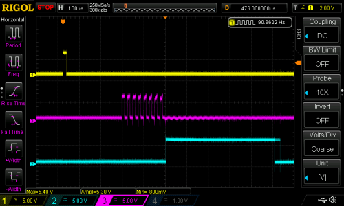
The scope trace to the right shows the sensor pointing at something relatively near. The top trace is the start pulse and the bottom trace is the input to the Arduino. The center trace is the output of the SONAR transducer. All the signal conditioning is inside the sensor, so you don’t need to worry about the actual signal processing to generate and recover the audio. You only need to measure the width of that bottom pulse.

The scope has persistence and you can see that the bottom trace does not always come out right at the same time (look at falling edge and you can see “ghosts” for previous samples. It shouldn’t come as a surprise that it may take a little effort to reduce the variations of the signal coming back from the SONAR.

Noise Reduction and Actions

Averaging

I wound up trying several different things to attempt to stabilize the input readings. The most obvious was to average more than one sample. The idea is that one or two samples that are way off will get wiped out by the majority of samples that are hovering around some center value. I also found that sometimes you just miss–especially when looking for fingers–and you get a very large number back. I elected to throw out any data that seemed way off when compared to the majority of received data.

Verifying

One other tactic I used was to verify certain elements with a second reading. For example, the start event occurs when the SONAR reports a value under the idle limit. The idle limit is a number less than the reading you get when the SONAR is pointed at the ceiling (or wherever it is pointing) and you don’t have anything blocking it. To recognize a valid start, the code reads twice to make sure the value is under the limit.

The code inside the Arduino loop is essentially a state machine. In the IDLE state, it looks for a reading that is below the idle limit. When found, that causes a transition to the sampling state. When the reading goes up or down more than some preset value, the code in the sample state sends a volume up or down key via the keyboard interface. If the sample goes back over the idle limit, the state machine returns to IDLE.

I got pretty good results with this data reduction,  but I also found the NewPing library and installed it. Even though it isn’t hard to write out a pulse and then read the input pulse, the NewPing library makes it even easier (and the code shorter). It also has a method, ping_median, that does some sort of data filtering and reduction, as well.

You can select either method by changing the USE_NEW_PING #define at the top of the file. Each method has different configuration parameters since the return values are slightly different between the two methods.

I said earlier that the code sends volume up and down commands when it detects action. Actually, the main code doesn’t do that. It calls an action subroutine and that subroutine is what sends the keys. It would be easy to make the program do other things, as well. In this case, it simply prints some debugging information and sends the keys (see below). I didn’t react to the actual position, although since the action routine gets that as a parameter, you could act on it. For example, you could make extreme positions move the volume up two or three steps at a time.

Sending Keyboard Commands

I wanted to send standard multimedia keys to the PC for volume up and down. Many keyboards have these already and usually your software will understand them with no effort on  your part. The problem, though, is that the default Arduino library doesn’t know how to send them.

Fortunately, I found an article about modifying the Arduino’s library to provide a Remote object that wasn’t exactly what I had in mind, but would work. Instead of sending keys, you have methods on a global Remote object that you can call to do things like change or mute the volume. The article was for an older version of the Arduino IDE, but it wasn’t hard to adapt it to the version I was using (version 2.1.0.5).

The action routine really only needs the UP_IN and DN_IN cases for this example. However, I put in all four branches for future expansion. Here’s the action subroutine:

void action(int why, unsigned value=0)
{
 Serial.print(value);
 switch (why)
 {
 case START_IN:
 Serial.println(" Start");
 break;
 case STOP_IN:
 Serial.println(" Stop");
 break;
 case UP_IN:
 Serial.println(" Up");
 Remote.increase();
 break;
 case DN_IN:
 Serial.println(" Down");
 Remote.decrease();
 break;
 }
}

The Final Result

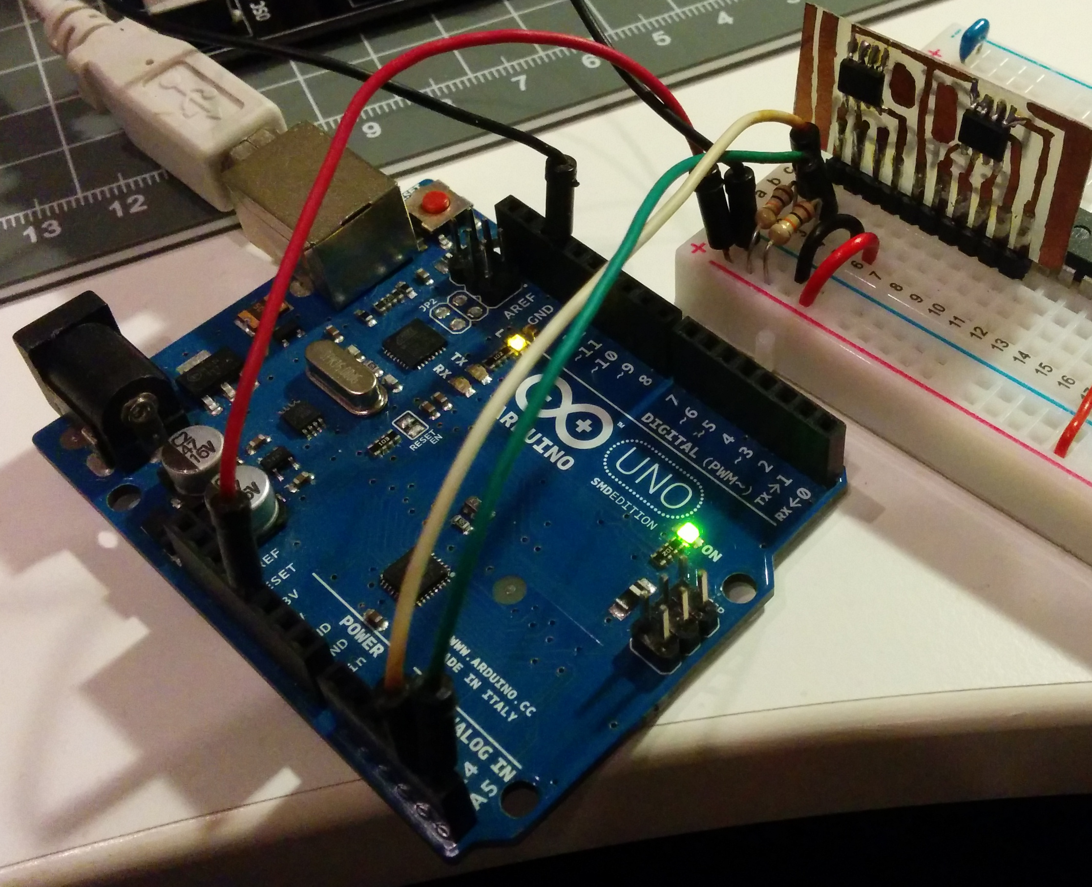
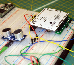
The final result works pretty well, although the averaging makes it less responsive than you might wish. You can turn down the number of samples to make it faster, but then it becomes unreliable. You can download the complete code from Github. The first thing you’ll want to do is check the top of the file to make sure your module is wired the same (pin 3 is the trigger pin and pin 8 is the echo return pin). You’ll also want to select if you are going to use the NewPing library or not. If you choose to use it, you’ll need to install it. I flipped my Leonardo upside down and mounted it on a breadboard with some adapters (see picture to right). It really needs a more permanent enclosure to be useful. Don’t forget to give the SONAR module its own 5V power supply.

If you look near the top of the loop function there is an #if statement blocking out 3 lines of code. Change the 0 to a 1 and you’ll be able to just get averaged data from the sensor. Put the module where you want it and see what kind of numbers you get. Depending on the method I used I was getting between 4000 and 9000 pointed up to the ceiling. Deduct a bit off of that for margin and change IDLETHRESHOLD (near the top of the file) to that number.

The DELTATHRESHOLD is adjustable too. The code sees any change that isn’t larger than that parameter as no change. You might make that bigger if you have shaky hands or smaller if you want to recognize more “zones”. However, the smaller the threshold, the more susceptible the system will be to noise. The display of samples is helpful because you can get an idea how much the readings vary when your hand is at a certain spot over the sensor. You can try using one or two fingers, but the readings are more reliable when the sound is bouncing off the fleshy part of your palm.

If you want to add some more gestures, you may have to track time a bit better. For example, holding a (relatively) stationary position for a certain amount of time could be a gesture. To get really sophisticated gestures, you may have to do some more sophisticated filtering of the input data than a simple average. A Kalman filter might be overkill, but would probably work well.

If you look around, many robots use these sensors to detect obstacles. Makes sense, they’re cheap and work reasonably well. There are also many projects that use these to show an estimate of distance (like an electronic tape measure). However, you can use them for many other things. I’ve even used a similar set up to measure the level of liquid in a tank and earlier this week we saw ultrasonic sensors used to monitor rice paddies.

If you really want to get serious, [uglyduck] has some analysis of what makes spurious readings on this device. He’s also redesigning them to use a different processor so he can do a better job. That might be a little further than I’m willing to go, although I was impressed with the 3D sonic touchscreen which also modified the SONAR units.


Filed under: Arduino Hacks, Featured, peripherals hacks

Stenography (Yes, with Arduinos)

What’s the fastest keyboard? Few subjects are as divisive in the geek community. Clicky or squishy? QWERTY or Dvorak? Old-school IBM or Microsoft Natural? The answer: none of the above.

The fastest normal-keyboard typists (Dvorak or Qwerty) can get around 220 words per minute (wpm) in bursts. That sounds fast, and it’s a lot faster than we type, but that’s still below the minimum speed allowable for certified court reporters or closed captioners. The fastest court reporters clock in around 350 to 375 wpm for testimony. But they do this by cheating — using a stenotype machine. We’ll talk more about stenography in a minute, but first a hack.

The Hack

[Kevin Nygaard] bought a used Stentura 200 stenotype machine off Ebay and it wasn’t working right, so naturally he opened it up to see if he could fix it. A normal stenotype operates stand-alone and prints out on paper tape, but many can also be connected to an external computer. [Kevin]’s machine had a serial output board installed, but it wasn’t outputting serial, so naturally he opened it up to see if he could fix it. In the end, he bypassed the serial output by soldering on an Arduino and writing a few lines of code.

The serial interface board in [Kevin]’s machine was basically a set of switches that made contact with the keys as they get pressed, and a few shift registers to read the state of these switches out over a serial connection. [Kevin] tapped into this line, read the switch state out into his Arduino, and then transmitted the correct characters to his computer via the Arduino’s serial over USB. (Video demo) As hardware types like to say, the rest is a simple matter of software.

Stenography 101

We’re big keyboard lovers. Maybe one third of Hackaday’s content is typed out on one or another vintage IBM Model M. No self-respecting geek who types for a living doesn’t have a near-religious keyboard preference. [Kevin]’s simple hack brought to our attention that we’ve never covered stenography. (Not steganography.) Frankly, we’re ashamed, and we’re fixing that right now.

The secret to the speed of steno is the use of a chorded, anatomically designed keyboard with an accompanying phonetic mnemonic shorthand system. Basically, one mashes down keys that correspond to sound of the word, and they’re interpreted according to a mnemonic system with a user-extensible dictionary. In short, it’s machine-assisted typing.

Many words are a single chord, and there are millions of possible chords, so there’s plenty of open space to add one’s own key combinations as the need arises.

But because stenography is a niche market, and because steno machines are designed to be used professionally by closed-captioners and court reporters, stenotype machines cost thousands of dollars. The software that runs them isn’t cheap either and is written for a very specific purpose, and is of course proprietary. In short, the market caters only to professionals, and there’s not much room for the steno enthusiast, until recently.

Plover: Open Software

Plover is free and open-source stenography software (Github), and is aiming to be the steno gateway drug. Specifically, Plover can turn a normal keyboard (with n-key rollover to support chording) into an emulated steno keyboard through software, allowing entry into the world of stenography for a hundred bucks instead of a few thousand.

Plover will also work with professional stenotypes that support serial output, like the one that [Kevin] modified that sent us down this rabbit hole in the first place. So once you’re hooked on steno, you can use your hard-earned dictionary with improved hardware if you want.

Note that the n-key rollover requirement is binding, and that’s where the $100 comes from. You can easily chord 20 keys on a stenotype machine because each finger has two buttons underneath it, and the chording systems are designed to take extensive use of hitting them two at a time. Some gaming keyboards have sufficient rollover capability, but it’s not a feature that’s demanded by the unwashed masses. In short, n-key rollover is going to cost you a little bit, or you can DIY. (Hint, hint.)

If you’ve played around with alternative keyboards (or just keyboard mappings) before, you’ll know that the Achilles’ Heel is how they handle the command and control characters that your favorite editor or IDE requires you to use. We had this hand-held device that made it nearly impossible to type control-x control-s, so it was goodbye keyboard or goodbye Emacs.

This is not a problem with a steno device, because you can define your own chord mappings. But you don’t have to stop with control characters or even Unicode. Map chords to commonly-used variable names. Map chords to entire flow-control structure skeletons (if-then-else). Think of steno strokes as being typing macros and you’ll get the idea.

The lead behind Plover, [Mirabai Knight], has a ton of info on getting started, including a live browser demo (a must-try!) and a video demonstrating Python (among other things) where you can see how chording works with coding. If you want to see how [Mirabai] transcribes live for clients using Plover and Vim, this video and its side pane are a great peek behind the curtains.

Open Steno Project: The Hardware

The Open Steno Project is an umbrella project on top of Plover to reduce the hardware and theory-learning hurdles. They list three keyboard options.

The Ergodox seems just to be a fancy ergonomic split keyboard, but one that would be particularly suited to stenography.

The Stenosaurus (Silicon-Valley-style empty sign-up page alert) looks sexy. That Stenosaurus is run by [Josh Lifton], the original coder heavyweight behind Plover who recently crowdfunded a batch of lightweight and quiet keyswitches, gives us hope. But hope and $4.35 will buy you a double-pump soy vanilla-whip latte; we like to see work in progress.

In contrast, the Stenoboard is an open project with actual designs, a 3D-printed case, code, and project examples. The firmware runs on an Arduino. StenoSpeak, an application based on the Stenoboard just won the second prize at the AT&T Connect Ability Hackathon, demonstrating that there’s other reasons to learn steno besides transcription. If you’re looking for some prior art for your own implementation, or a place to jump in and contribute, Stenoboard is a good bet.

Conclusion

We’re surprised that we found so few DIY projects on the steno front. The hardware is fundamentally simple, with obvious directions for improvements and personalizations. A stenotype is extremely costly to purchase, but cheap to DIY. The software side is well-established and open source. In short, the ball is set up for a quick hardware field goal.

On Hackaday.io and the blog, there are tons of projects for making improved keyboards — many of them are chorded. But so far all of them ignore the stenotype, the current state of the art in high speed typing that’s been around since the late 1800s. We want to see this change, and we think the tide is high and the planets aligned and so on. Fly, winged monkeys, fly!


Filed under: Arduino Hacks, Featured, peripherals hacks

Disassembled Mouse Keeps Track Of Gas Meter

After building devices that can read his home’s electricity usage, [Dave] set out to build something that could measure the other energy source to his house: his gas line. Rather than tapping into the line and measuring the gas directly, his (much safer) method was to simply monitor the gas meter itself.

The major hurdle that [Dave] had to jump was dealing with an ancient meter with absolutely no modern electronics like some other meters have that make this job a little easier. The meter has “1985” stamped on it which might be the manufacturing date, but for this meter even assuming that it’s that new might be too generous. In any event, the only option was to build something that could physically watch the spinning dial. To accomplish this, [Dave] used the sensor from an optical mouse.

The sensor is surrounded by LEDs which illuminate the dial. When the dial passes a certain point, the sensor alerts an Arduino that one revolution has occurred. Once the Arduino has this information, the rest is a piece of cake. [Dave] used KiCad to design the PCB and also had access to a laser cutter for the enclosure. It’s a great piece of modern technology that helps integrate old analog technology into the modern world. This wasn’t [Dave]’s first energy monitoring system either; be sure to check out his electricity meter that we featured a few years ago.


Filed under: peripherals hacks

Embed with Elliot: I2C Bus Scanning

A lot of great ICs use I2C to communicate, but debugging a non-working I2C setup can be opaque, especially if you’re just getting started with the protocol/bus. An I2C bus scanner can be a helpful first step in debugging an I2C system. Are all the devices that I think should be present actually there and responding? Do they all work at the bus speed that I’m trying to run? If you’ve got an Arduino or Bus Pirate sitting around, you’re only seconds away from scanning your I2C bus, and answering these questions.

The Lowdown: I2C in Brief

I2C is a two-wire (plus ground) communications bus and protocol. The physical layer is just two signal wires: a clock line (SCL) that’s controlled by the master, and a data line (SDA) that can be controlled by either the master or the addressed slave unit. Data is always read on the SDA line when the clock is high, and a new value is established while the clock is low. The two exceptions to this rule are the stop and start signals, where the master is allowed to raise and drop the data line while the clock is still high. Because this change shouldn’t ever happen during data transfer, the stop and start signals are easy to detect.

All data is sent in eight-bit packets and each packet is acknowledged by the recipient, whether master or slave. To start up a conversation, the master sends the start signal and then the seven-bit address of the slave device that it wants to speak to. The eighth bit in the master’s first packet tells the slave whether the master is going to transmit more data (a “write” command, a zero) or whether the master is requesting data back from the slave (a “read” value, a one).

After the eight bits are sent, the slave is required to acknowledge receipt by pulling the data line low.  This acknowledge signal is exactly what the I2C bus scanning software will need to look for in order to detect a chip with the given address on the bus.

There are, of course, a lot more complicating details to I2C. For instance, there are a whole range of permissible clock speeds at which the transmissions can take place: ranging from the default 100kHz data rate, through 400kHz “fast mode”, 1MHz “fast mode plus”, and up as far as 5MHz “ultra-fast mode”. (We await the 10MHz “super-duper, really-really-fast mode” with baited breath.) And since the bus is clocked by the SCL line, almost any slower data rate up to the maximum allowed will work just fine.

The physical lines are pulled up to a logic-high voltage level by pullup resistors, and the devices signal low by pulling the line down. This means that the voltage transitions can be a little blurry, especially on long runs or other situations where the line itself capacitively couples to the circuit. These physical factors will play a role in determining how fast you can send signals on the I2C bus, and you may need to fine-tune the pullup resistors in your particular system.

There are a surprisingly large number of other ways that things can go wrong on an I2C bus, so it’s great to be able to start debugging at the very beginning — is the slave even getting my first (address) packet at the speed I’m sending? Hence the utility of an I2C scanner.

A Scanner

A first cut at an I2C bus scanner, then, can be made by just cycling through all 127 possible slave device addresses, and checking whether or not they acknowledge. Next, you might want to re-run the same test at a bunch of different bus speeds, if you thought that you might be having troubles with signal rise- and fall-times. Finally, and we’ve never seen this implemented, it might be cool to have a database of common I2C slave device addresses so that the scanner itself can report back which particular chips it’s found.

For the Arduino, the most featureful scanner we’ve seen is posted on the Arduino forums, with the code hosted on Github, in the “sketches/MultiSpeedI2CScanner” folder.  It actually does everything that we’d want in a simple scanner: scans the entire bus at different speeds and plots the results out nicely over the serial port for perusal on your computer. It’s configured to do a full scan on reboot. Type “ps” to print only the found devices and start a scan. Bam!

The one caveat with the Arduino scanner is that if you’ve neglected to connect pullup resistors on the SDA and SCL lines (we would never!) the scanner seems to hang somewhere when running at 800kHz. We suspect it’s waiting to become bus master and just gets stuck; we wonder why there’s not a timeout in the twi_writeTo() function in the Arduino “twi.c” library. (Anyone have a good guess?) Other speed modes worked just fine, and everything was peachy again after adding a 10k pullup resistor to SDA.

Naturally, the Bus Pirate (the swiss-army knife of serial communications) will do an I2C scan. It only runs one frequency at a time, but it’s quick enough that you can step through them all in short order. It’s got a quirk, or maybe a feature; it treats the read/write bit as part of the address, so it will test each chip in both directions. Enter the I2C mode, set the desired speed and pullup/power options, and finally type “(1)” for option 1: 7-bit address search. You should see all the devices that responded on the bus listed out for you.

Writing your own code to do a scan is surprisingly simple as well, if you know the chips you’re working with. Most microcontrollers’ dedicated hardware I2C interfaces will report error codes in a specific register. If you can figure out how to test for the “didn’t acknowledge after sending the address and data-direction packet” error, the code pretty much writes itself.

Going Further

Once you’ve got the basics verified — the slave responds when addressed at the desired speed — and your I2C setup still isn’t working, you’re on to debugging the harder problems. There are other tests you might like to do, but unfortunately they all run quickly into the slave-device specific command sets. For instance, many devices will receive a command to reply with a known device ID, or the contents of a default register, or similar. These are useful to make certain that you’ve got multi-byte commands working as expected.

If you suspect that you’re having problems with the signals not rising or falling fast enough, perhaps because you’ve seen chips respond at low speeds but not at higher ones during the scan above, you’re going to need an oscilloscope to actually probe out the analog voltages on the lines. Or try lower-value pullup resistors to speed up the rising edges and test again.

Harder to catch or infrequently occurring glitches on a multi-master I2C bus get really hard to track down really fast. But getting the simple stuff verified working first — all parts are on the addresses that you think they are — can get you set on the right path.

Good luck with your I2C projects! And if you’ve got any other useful I2C debugging tools or strategies up your sleeves, feel free to discuss in the comments.


Filed under: Hackaday Columns, Microcontrollers, peripherals hacks

Using RC Transmitters With Flight Simulators

It’s winter, and that means terrible weather and very few days where flying RC planes and helicopters is tolerable. [sjtrny] has been spending the season with RC flight simulators for some practice time. He had been using an old Xbox 360 controller, but that was really unsuitable for proper RC simulation – a much better solution would be to use his normal RC transmitter as a computer peripheral.

The usual way of using an RC transmitter with a computer is to buy a USB simulator adapter that emulates a USB game pad through a port on the transmitter. Buying one of these adapters would mean a week of waiting for shipping, so [sjtrny] did the logical thing and made his own.

Normally, a USB simulator adapter plugs in to a 3.5mm jack on the transmitter used for a ‘buddy box’, but [sjtrny] had an extra receiver sitting around. Since a receiver simply outputs signals to servos, this provides a vastly simpler interface for an Arduino to listen in on. After connecting the rudder, elevator, aileron, and throttle signals on the receiver to an Arduino, a simple bit of code and the UnoJoy library allows any Arduino and RC receiver to become a USB joystick.

[sjtrny] went through a second iteration of hardware for this project with a Teensy 3.1. This version has higher resolution on the joystick axes, and the layout of the code isn’t slightly terrible. It’s a great project for all the RC pilots out there that can’t get a break in the weather, and is also a great use for a spare receiver you might have sitting around.


Filed under: peripherals hacks, radio hacks

Dial is a Simple and Effective Wireless Media Controller

[Patrick] was looking for an easier way to control music and movies on his computer from across the room. There is a huge amount of remote control products that could be purchased to do this, but as a hacker [Patrick] wanted to make something himself. He calls his creation, “Dial” and it’s a simple but elegant solution to the problem.

Dial looks like a small cylindrical container that sits on a flat surface. It’s actually split into a top and bottom cylinder. The bottom acts as a base and stays stationary while the top acts as a dial and a push button. The case was designed in SOLIDWORKS and printed on a 3D printer.

The Dial runs on an Arduino Pro mini with a Bluetooth module. The original prototype used Bluetooth 2.0 and required a recharge after about a day. The latest version uses the Bluetooth low energy spec and can reportedly last several weeks on a single charge. Once the LiPo battery dies, it can be recharged easily once plugged into a USB port.

The mechanical component of the dial is actually an off-the-shelf rotary encoder. The encoder included a built-in push button to make things easier. The firmware is able to detect rotation in either direction, a button press, a double press, and a press-and-hold. This gives five different possible functions.

[Patrick] wrote two pieces of software to handle interaction with the Dial. The first is a C program to deal with the Bluetooth communication. The second is actually a set of Apple scripts to actually handle interaction between the Dial and the various media programs on his computer. This allows the user to more easily write their own scripts for whatever software they want. While this may have read like a product review, the Dial is actually open source!


Filed under: Arduino Hacks, peripherals hacks