Posts with «optical» label

Paper Tape Reader Self-calibrates, Speaks USB

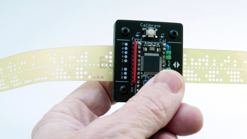
Input devices consisting of optical readers for punched paper tape have been around since the earliest days of computing, so why stop now? [Jürgen]’s Paper Tape Reader project connects to any modern computer over USB, acting like a serial communications device. Thanks to the device’s automatic calibration, it works with a variety of paper materials. As for reading speed, it’s pretty much only limited to how fast one can pull tape through without damaging it.

Stacked 1.6 mm PCBs act as an enclosure, of sorts.

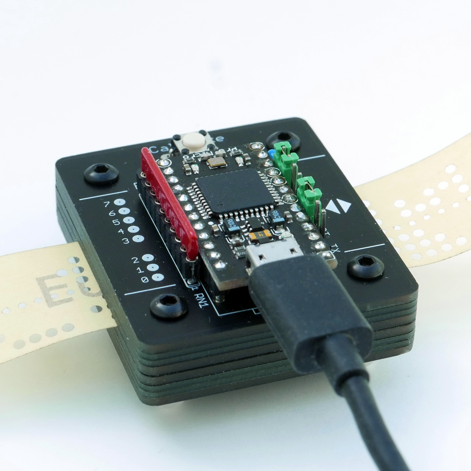
While [Jürgen]’s device uses LEDs and phototransistors to detect the presence or absence of punched holes, it doesn’t rely on hardware calibration. Instead, the device takes analog readings of each phototransistor, and uses software-adjusted thresholds to differentiate ones from zeros. This allows it to easily deal with a wide variety of tape types and colors, even working with translucent materials. Reading 500 characters per second isn’t a problem if the device has had a chance to calibrate.

Interested in making your own? The build section of the project has all the design files; it uses only through-hole components, and since the device is constructed from a stack of 1.6 mm thick PCBs, there’s no separate enclosure needed.

Paper tape and readers have a certain charm to them. Cyphercon 4.0 badges featured tape readers, and we’ve even seen the unusual approach of encoding an I2C byte stream directly onto tape.

A low-cost approach to Intrinsic optical signal

Leonardo Lupori and Raffaele Mazziotti are active in the field of neuroscience at Tommaso Pizzorusso’s lab at Neuroscience Institute CNR of Pisa respectively as molecular biologist and experimental psychologist. They created an Arduino-based and MATLAB-controlled tool called IOSIC (Intrinsic Optical Signal Imaging Chamber), powered by an Arduino Micro and focused on intrinsic optical signal (IOS) imaging apparatus to run experiments on the plasticity of the brain.

Intrinsic optical signal (IOS) imaging is a functional imaging technique that has revolutionized our understanding of cortical functional organization and plasticity since it was first implemented, around 30 years ago. IOS is produced by the brain when processing information and is similar to the information recorded with the plethysmograph (the instrument to measure heart rate from a finger) and it is useful to investigate how the brain works. The researchers are especially interested to investigate how the brain is able to adapt to the environment to store information but also acquire new skills and these studies are really useful to understand what happens to the brain when is in good health or during a disease.

Even if their lab has a long-standing expertise in electrophysiological studies, they decided to  developed a fully functional apparatus for IOS with tools already available and low-cost:

To set up the entire system we used a mix of components commercially available and custom-made. The most expensive tool we used is an imaging camera from Hamamatsu (it is necessary because we need to analyze data quantitatively), but you can also use a cheaper camera (at least with a CCD chip 12-bit depth is recommended). The rest is stuff collected from old tools of the lab. For example, the microscope, that in our case is an old Olympus confocal microscope, but any transmitted light microscope or macroscope should be ok, was already in the lab and is currently used also for other purposes. For light illumination, we used a custom made crown-shaped LED holder that can be attached to the objective and provide a really stable light source. Afterwards, we wrote a MATLAB script to control the camera and then we built an imaging chamber to analyze the animal preparation. The imaging chamber is essential to keep the animal stable during the imaging session (about 7 minutes) and also to maintain its physiological temperature during the time course of anesthesia. An additional feature added to the chamber is the possibility to change the animal’s visual field automatically allowing us to measure rapidly, efficiently and repeatedly a very important parameter of plasticity called ocular dominance. The chamber is composed by a 3D printed structure on which an Arduino MICRO, two servo motors, a heating pad, an IR thermometer and a magnetic ring have been installed. Currently we are using this system with success and we hope to discover something really relevant.

You can download IOSIC code for the Arduino MICRO here. The code uses third-party libraries : TMP006 and Servo. MATLAB code to control shutters is available here.

Disassembled Mouse Keeps Track Of Gas Meter

After building devices that can read his home’s electricity usage, [Dave] set out to build something that could measure the other energy source to his house: his gas line. Rather than tapping into the line and measuring the gas directly, his (much safer) method was to simply monitor the gas meter itself.

The major hurdle that [Dave] had to jump was dealing with an ancient meter with absolutely no modern electronics like some other meters have that make this job a little easier. The meter has “1985” stamped on it which might be the manufacturing date, but for this meter even assuming that it’s that new might be too generous. In any event, the only option was to build something that could physically watch the spinning dial. To accomplish this, [Dave] used the sensor from an optical mouse.

The sensor is surrounded by LEDs which illuminate the dial. When the dial passes a certain point, the sensor alerts an Arduino that one revolution has occurred. Once the Arduino has this information, the rest is a piece of cake. [Dave] used KiCad to design the PCB and also had access to a laser cutter for the enclosure. It’s a great piece of modern technology that helps integrate old analog technology into the modern world. This wasn’t [Dave]’s first energy monitoring system either; be sure to check out his electricity meter that we featured a few years ago.


Filed under: peripherals hacks

Turning A Cheap Optical Mouse Into A Robot Odometer

John Graham-Cumming (JGC), author of The Geek Atlas, wrote in to let us know about a fun conversion he did with a cheap optical mouse:

For a small robot project I’m working on I needed a way to measure the robot’s progress across the floor. There are various possibilities, such as: use stepper motors (expensive and am recycling some old continuous run servos), add an encoder to the wheels (would need to go buy some parts for that), or use the optical sensor for a mouse.

I had a really old PS/2 optical mouse lying around which contains an MCS-12085 optical sensor that has a rather simple serial interface suitable for connection to a microcontroller. Inside there are two separate areas of components. On the right in the picture above is the PS/2 interface chips and four nice extras that I desoldered for later use (three microswitches and a quadrature encoder)…

This is a great example of repurposing something that might otherwise go to a landfill; and to top it off, JGC has posted some code you can use as an Arduino interface to the optical mouse sensor. Read all about his conversion at his blog.


The Geek Atlas
128 Places Where Science and Technology Come Alive
The history of science is all around us, if you know where to look. With this unique traveler’s guide, you’ll learn about 128 destinations around the world where discoveries in science, mathematics, or technology occurred or is happening now. Travel to Munich to see the world’s largest science museum, watch Foucault’s pendulum swinging in Paris, ponder a descendant of Newton’s apple tree at Trinity College, Cambridge, and more.
Filed under: Arduino, Mods
MAKE » Arduino 15 Sep 23:00