Posts with «musical hacks» label

Upgrading a MIDI Controller with an FPGA

While the “M” in MIDI stands for “musical”, it’s possible to use this standard for other things as well. [s-ol] has been working on a VJ setup (mixing video instead of music) using various potentiometer-based hardware and MIDI to interface everything together. After becoming frustrated with drift in the potentiometers, he set out to outfit the entire rig with custom-built encoders.

[s-ol] designed the rotary-encoder based boards around an FPGA. It monitors the encoder for changes, controls eight RGB LEDs per knob, and even does capacitive touch sensing on the aluminum knob itself. The FPGA communicates via SPI with an Arduino master controller which communicates to a PC using a serial interface. This is [s-ol]’s first time diving into an FPGA project and it looks like he hit it out of the park!.

Even if you’re not mixing video or music, these encoders might be useful to any project where a standard analog potentiometer isn’t accurate or precise enough, or if you just need something that can dial into a specific value quickly. Potentiometers fall short in many different ways, but if you don’t want to replace them you might modify potentiometers to suit your purposes.

Probability-Based Drummer Leaves The Beats Up To Chance

Drum machines may seem like one of the many rites of passage for hardware makers, they’re a concept you can implement simply or take into the extreme making it as complex as you want. [Matt’s] DrumKid is one of them, and its long development history is wonderfully documented in the project logs.

[Matt’s] original intention was to use the automatic drummer as part of his band, wanting “the expressiveness of a good drummer but without the robotic tendencies of a simple drum machine”. For that, he created the first iteration of the DrumKid, a web-based project using the Web Audio API. The interface consisted of bars showing levels for different settings which could be intuitively tweaked, changing the probability of a drum sound being played. This gave the “drummer” its unpredictability, setting itself apart from any regular old drum machine.

Fast forward a few years, and [Matt] now wants to recreate his DrumKid as a proper piece of musical gear, porting the concept into a standalone hardware drum machine you can plug into your mixer. He decided to go with the Arduino framework for his project rather than the Teensy platform in order to make it cheaper to build. The controls are simplified down to a few buttons and potentiometers, and the whole thing runs off of three AAA batteries. Also, targeting the project for hardware like this allowed for new features to be added, such as a bit-crush filter.

We already saw the first prototype here on Hackaday when it was featured in a Hackaday Prize mentor session, and it’s nice to see how the project evolved since. After a number of revisions, the new prototype takes design cues from Teenage Engineering’s “Pocket Operator” drum machine, using the main PCB as its own faceplate rather than a 3D printed case in a familiar way we’ve seen before. Unfortunately, the latest board is non-functional due to a routing mistake, but you can see the previous working prototypes in his project logs.

The HackadayPrize2019 is Sponsored by:

Weather Station Can Rock You Like A Hurricane

People love to talk about the weather. It’s the perfect small talk, whether you’re trying to start a conversation or keep one going by avoiding an awkward silence. In the same fashion, weather stations are an ideal starting point for any sort of sensor-related project ideas. You get to familiarizing yourself with communication buses, ADCs, general data acquisition, and you learn a lot in figuring out how to visualize it all.

What if your weather station didn’t visualize anything? [OttoNL] is answering that question with a MIDI-generating Weather Station that uses the mood of the music to convey the condition of the elements outside.

Using an ESP8266 programmed via the Arduino IDE, [OttoNL] hooked up a light dependent resistor, a rain sensor, and the all-round workhorse BME280 for temperature, barometric pressure, and humidity to it. Reading the sensors, the ESP will generate MIDI notes that are sent to a connected synthesizer, with each sensor influencing a different aspect of the generated MIDI signals. A sadder, slow tune will play during rain and a fast upbeat one during sunshine. While it doesn’t use the ESP’s WiFi functionality at all at this point, a future version could easily retrieve some weather forecast data from the internet and add it into the mix as well.

Connect this to your alarm clock, and you can start your day off in the appropriate mood. You can even customize your breakfast toast to really immerse your morning routine in abstract weather cues.

Creating A Sonic Landscape With Glitching CD Player

CDs were a great advancement in audio quality when they were first put on the market. There’s no vinyl-style degradation of the medium if it’s played over and over, and there’s no risk of turning them into a giant pile of ribbon while rewinding like a cassette tape. The one downside was that if you were to take them on the move you needed special hardware and software to prevent the inevitable skipping. If you look at the skipping not as a downside, though, but as a way to produce interesting music, you might end up with a pretty unique piece of hardware.

[Dmitry] is known for his interesting art installations, and the latest one uses parts from three 1988 Sony D2 CD players that have been reassembled in order to take advantage of a skipping and glitching CD. The modified equipment is able to play during pause or rewind thanks to a processor modification, and can also change the rotational speed of the disc. There are other pieces of hardware included for more fine control of glitching and skipping of the audio being read off of the CD.

The new device functions as a working musical instrument, although [Dmitry] says that it is more useful for deconstructing the information stored on the disc, and exploring the medium itself. Of course if you have enough motivation, you can find sounds from almost anywhere on (or in) the planet too.

Hack a Day 28 May 06:00

Make Your Own MIDI Controller With An Arduino

Engineers create something out of nothing, and no where is this more apparent than in the creation of customized computer hardware. To make a simple MIDI controller, you need knowledge of firmware design and computer architecture, you need knowledge of mechanical design, and you need to know electronic design. And then you need the actual working knowledge and experience to wield a tool, be it a hammer, laser cutter, or an IDE. [Mega Das] brought together all of these skill to build a MIDI controller. Sure, it’s for bleeps and bloops coming out of a speaker, but take a step back and realize just how awesome it is that any one person could imagine, then implement such a device.

The electronics for this build include a printed circuit board that serves to break out the connections on an Arduino nano to a dozen arcade push buttons, four slide pots, two rotary pots, and a handful of screw terminals to connect everything together. Mechanically, this is a laser-cut box engraved with some fancy graphics and sized perfectly to put everything inside.

Yes, we’ve seen a lot of MIDI controllers built around the Arduino over the years, but this one is in a class by itself. This is taking off-the-shelf parts and customizing them to exactly what you want, and a prodigious example of what is possible with DIY hardware creation. You can check out the build video below.

Laser Light Show Turned Into Graphical Equalizer

The gold standard for laser light shows during rock concerts is Pink Floyd, with shows famous for visual effects as well as excellent music. Not all of us have the funding necessary to produce such epic tapestries of light and sound, but with a little bit of hardware we can get something close. [James]’s latest project is along these lines: he recently built a laser light graphical equalizer that can be used when his band is playing gigs.

To create the laser lines for the equalizer bands, [James] used a series of mirrors mounted on a spinning shaft. When a laser is projected on the spinning mirrors it creates a line. From there, he needed a way to manage the height of each of the seven lines. He used a series of shrouds with servo motors which can shutter the laser lines to their appropriate height.

The final part of the project came in getting the programming done. The brain of this project is an MSGEQ7 which  takes an audio input signal and splits it into seven frequencies for the equalizer. Each one of the seven frequencies is fed to one of the seven servo-controlled shutters which controls the height of each laser line using an Arduino. This is a great project, and [James] is perhaps well on his way to using lasers for other interesting musical purposes.

Hack a Day 14 Feb 03:00

Well-Loved Toy Turned Into Robotic Glockenspiel

If there’s a happier word ever imported into the English language than “Glockenspiel”, we’re not sure what it is. And controlling said instrument with a bunch of servos and an Arduino makes us just as happy.

When [Leon van den Beukel] found a toy glockenspiel in a thrift store, he knew what had to be done – Arduinofy it. His first attempt was a single hammer on a pair of gimballed servos, which worked except for the poor sound quality coming from the well-loved toy. The fact that only one note at a time was possible was probably the inspiration for version two, which saw the tone bars removed from the original base, cleaned of their somewhat garish paint, and affixed to a new soundboard. The improved instrument was then outfitted with eight servos, one for each note, each with a 3D-printed arm and wooden mallet. An Arduino runs the servos, and an Android app controls the instrument via Bluetooth, because who doesn’t want to control an electronic glockenspiel with a smartphone app? The video below shows that it works pretty well, even if a few notes need some adjustment. And we don’t even find the servo noise that distracting.

True, we’ve featured somewhat more accomplished robotic glockenspielists before, but this build’s simplicity has a charm of its own.

Racing the Beam and Dropping Some Beats

The heart of the Atari 2600 wasn’t the 6502 (or the 6507 for the pedants), it was the TIA chip. This is the chip responsible for drawing graphics on the display, racing the beam, and extremely limited support for sound generation. We haven’t seen many attempts of using the Atari 2600 for chiptunes, but that doesn’t mean it can’t be done. [John Sutley]’s Syndrum, a take on an Atari 2600 drum machine is nearly a work of art. It’s a custom cartridge for the wood-paneled Atari, and an impressive input device that turns this classic console into a beat machine

Did the Atari 2600 ever come with a drum machine cartridge? Maybe. Probably not. [John] originally built this project to experiment with the TIA chip, but found it was less tonal than a kazoo. That struck ‘Atari synthesizer’ off the list and replaced it with an ‘Atari drum machine’. There are two key parts of the build here, the first being a repurposed Asteroids cartridge that had the PROM replaced with a ZIF socket. This allows [John] to easily burn new code to an EEPROM, stuff it in the socket, and run it on the Atari. All the code was developed with batari Basic, a BASIC-inspired language that spits out .bin files for the Atari.

But running code on the Atari is just one half of this build. To do a drum machine, you somehow need to tell the Atari when to play each sound. Given the lack of expansion capabilities for the Atari, [John] turned to the controller port. The Syndrum uses Arduino Nano to bridge the DE9 controller connector to a MIDI port. Yes, it’s real MIDI, on a machine that could probably never do MIDI natively (although we’d love to see someone try).

Need a video of this mind-blowing hack in action? Here you go:

Ask Hackaday Answered: The Tale of the Top-Octave Generator

We got a question from [DC Darsen], who apparently has a broken electronic organ from the mid-70s that needs a new top-octave generator. A top-octave generator is essentially an IC with twelve or thirteen logic counters or dividers on-board that produces an octave’s worth of notes for the cheesy organ in question, and then a string of divide-by-two logic counters divide these down to cover the rest of the keyboard. With the sound board making every pitch all the time, the keyboard is just a simple set of switches that let the sound through or not. Easy-peasy, as long as you have a working TOG.

I bravely, and/or naïvely, said that I could whip one up on an AVR-based Arduino, tried, and failed. The timing requirements were just too tight for the obvious approach, so I turned it over to the Hackaday community because I had this nagging feeling that surely someone could rise to the challenge.

The community delivered! Or, particularly, [Ag Prismatic]. With a clever approach to the problem, some assembly language programming, and an optional Arduino crystalectomy, [AP]’s solution is rock-solid and glitch-free, and you could build one right now if you wanted to. We expect a proliferation of cheesy synth sounds will result. This is some tight code. Hat tip!

Squeezing Cycles Out of a Microcontroller

Let’s take a look at [AP]’s code. The approach that [AP] used is tremendously useful whenever you have a microcontroller that has to do many things at once, on a rigid schedule, and there’s not enough CPU time between the smallest time increments to do much. Maybe you’d like to control twelve servo motors with no glitching? Or drive many LEDs with binary code modulation instead of primitive pulse-width modulation? Then you’re going to want to read on.

There are two additional tricks that [AP] uses: one to fake cycles with a non-integer number of counts, and one to make the AVR’s ISR timing absolutely jitter-free. Finally, [Ag] ended up writing everything in AVR assembly language to make the timing work out, but was nice enough to also include a C listing. So if you’d like to get your feet wet with assembly, this is a good start.

In short, if you’re doing anything with hard timing requirements on limited microcontroller resources, especially an AVR, read on!

Taking Time to Think
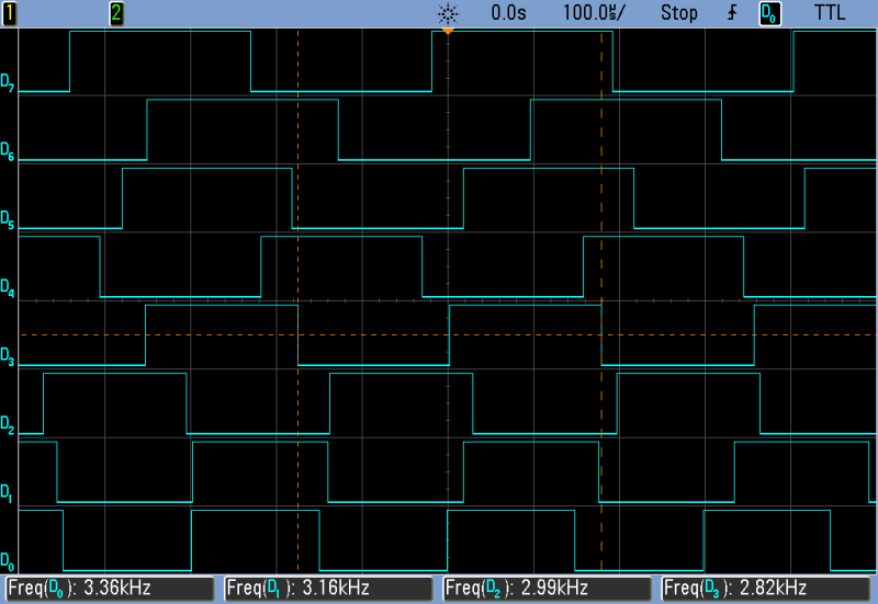
The goal of the top-octave generator is to take an input clock and divide it down into twelve simultaneous sub-clocks that all run independently of each other. Just to be clear, this means updating between zero and twelve GPIO pins at a frequency of 1 MHz or so — updating every twenty clock cycles at the AVR’s maximum CPU speed. If you thought you could loop through twelve counters and decide which pins to flip in twenty cycles, you’d be mistaken.

But recognizing the problem is the first step to solving it. Although the tightest schedule might require flipping one pin exactly twenty clocks after flipping another, most of the time there are more cycles between pin updates — hundreds up to a few thousand. So the solution is to recognize when there is time to think, and use this time to pre-calculate a buffer full of next states.
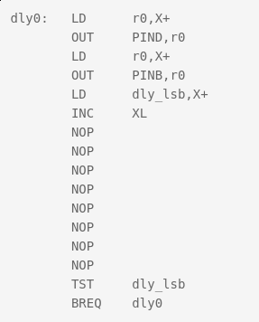
[Ag]’s solution uses a few different loops that run exactly 20, 40, and 60 cycles each — the longer versions being just the 20-cycle one padded out with NOPs. These loops run inside an interrupt-service routine (ISR). When there are 80 or more cycles of thinking time until the next scheduled pin change, control is returned to the main loop and the next interrupt is set to re-enter the tight loops at the next necessary update time.

All the fast loop has to do is read two bytes, write them out to the GPIO pins, increment the pointer to the next row of data, and figure out if it needs to stall for 20 or 40 additional cycles, or set the ISR timer for longer delays and return to calculations. And this it can do in just twelve of the twenty cycles! Slick.

Buffers

Taking a step back from the particulars of the top-octave generator, this is a classic problem and a classic solution. It’s worth your time to internalize it, because you’ll run into this situation any time you have real-time constraints. The problem is that on average there’s more than enough time to complete the calculations, but that in the worst cases it’s impossible. So you split the problem in two parts: one that runs as fast as possible, and one that does the calculations that the fast section will need. And connecting together fast and slow processes is exactly why computer science gave us the buffer.

In [AP]’s code, this buffer is a table where each entry has two bytes for the state of the twelve GPIO pins, and one byte to store the number of clock cycles to delay until the next update. One other byte is left empty, yielding 64 entries or 256 bytes for the whole table. Why 256 bytes? Because the AVR has an 8-bit unsigned integer, wrapping around from the end of the table back to the beginning is automatic, saving a few cycles of wasteful if statements.

But even with this fast/slow division of labor, there is not much time left over for doing the pre-calculation. Sounding the highest C on a piano keyboard (4186 Hz) with a 20 MHz CPU clock requires toggling a GPIO pin every 2,390 cycles, so that’s the most time that the CPU will ever see. When the virtual oscillators are out of phase, this can be a lot shorter. By running the AVR at its full 20 MHz, and coding everything in assembly, [AP] can run the calculations fast enough to support twelve oscillators. At 16 MHz, there’s only time for ten, so every small optimization counts.

Some Optimization Required

Perhaps one of the cleverest optimizations that [AP] made is the one that makes this possible at all. The original top-octave chips divide down a 2 MHz square wave by a set of carefully chosen integer divisors. Running the AVR equivalent at 2 MHz resolution would mean just ten clocks per update and [AP]’s fast routine needed twelve, so the update rate would have to be halved. But that means that some odd divisors on the original IC would end up non-integral in the AVR code. For example, the highest C is reproduced in silicon as 2 MHz / 239, so to pull this off at 1 MHz requires counting up to 119.5 on an integer CPU. How to cope?

You could imagine counting to 119 half of the time, and 120 the other. Nobody will notice the tiny difference in duty cycle, and the pitch will still be spot on. The C programmer in me would want to code something like this:

uint8_t counter[12] = { 0, ... };
uint8_t counter_top[12] = { 119, ... };
uint8_t is_counter_fractional[12] = { 1, 0, ... };
uint8_t is_low_this_time[12] = { 0, ... };

// and then loop
for ( i=0 ; i<12; ++i){
  if ( counter[i] == 0 ){
    if ( is_counter_fractional[i] ){
      if ( is_low_this_time[i] ){
        counter[i] = counter_top[i];
    is_low_this_time = 0;
      else {
        counter[i] = counter_top[i] + 1;
    is_low_this_time = 1;
      }
    }
  }
}

That will work, but the ifs costs evaluation time. Instead, [AP] did the equivalent of this:

uint8_t counter[12] = { 0, ... };
uint8_t counter_top[12] = { 119, ... };
uint8_t phase[12] = { 1, 0, ... };

for ( i=0 ; i<12; ++i){
  if ( counter[i] == 0 ){
    counter[i] = counter_top[i] + phase[i];
    counter_top[i] = counter[i];
    phase[i] = -phase[i];
  }
}

What’s particularly clever about this construction is that it doesn’t need to distinguish between the integer and non-integer delays in code. Alternately adding and subtracting one from the non-integer values gets us around the “half” problem, while setting the phase variable to 0 means that the integer-valued divisors run unmodified, with no ifs.

The final optimization shows just how far [AP] went to make this AVR top-octave generator work like the real IC. When setting the timer to re-enter the fast loop in the ISR, there’s the possibility for one cycle’s worth of jitter. Because AVR instructions run in either one or two clock cycles, it’s possible that a two-cycle instruction could be running when the ISR timer comes due. Depending on luck, then, the interrupt will run four or five clocks later: see the section “Interrupt Response Time” in the AVR data sheet for details.

In a prologue to the ISR, [AP]’s code double-checks the hardware timer to see if it has entered on a one-cycle instruction, and adds in an extra NOP to compensate. This makes the resulting oscillator nearly jitter free, pushing out a possible source of 50 ns (one cycle at 20 MHz) slop. I don’t think you’d be able to hear this jitter, but the result surely looks pretty on the oscilloscope, and this might be a useful trick to know if you’re ever doing ultra-precise timing with ISRs.

The Proof of the Pudding

Naturally, I had to test out this code on real hardware. The first step was to pull a random Arduino-clone out of the closet and flash it in. Because “Arduinos” run at 16 MHz with the stock crystal, the result is that a nominal 440 Hz concert A plays more like a slightly sharp F, a musical third down. It sounds fine on its own, but you won’t be able to play along with any other instruments that are tuned to 440 Hz.

[AP]’s preferred solution is to run the AVR chip at 20 MHz. Since the hardware requirements are very modest, you could use a $0.50 ATTiny816 coupled with a 20 MHz crystal and you’d have a top-octave generator for literal pocket change — certainly cheaper than buying even an Arduino clone. I tested it out with an ATMega48P and a 20 MHz crystal on a breadboard because it’s what I had. Or you could perform crystalectomy on your Arduino to get it running at full speed.

We went back and forth via e-mail about all the other (firmware) options. [AP] had tried them all. You could trim the ISR down to 16 cycles and run at 16 MHz, but then there’s only enough CPU time in the main loop to support ten notes, two shy of a full octave. You could try other update rates than 1 MHz, but the divisors end up being pretty wonky. To quote [AP] from our e-mail discussion on the topic:

“After playing with the divider values from the original top octave generator IC and trying different base frequencies, it appears that the 2 MHz update rate is a “sweet spot” for getting reasonable integer divisors with < +/-2 cents of error. The original designers of the chip must have done the same calculations.”

To make a full organ out of this setup, you’ll also need twelve binary counter chips to divide down each note to fill up the lower registers of the keyboard, but these are easy to design with and cost only a few tens of cents apiece. All in all, thanks to [AP]’s extremely clever coding, you can build a fully-polyphonic noisemaker that spits out 96 simultaneous pitches, all in tune, for under $10. That’s pretty amazing.

And of course, I’ve already built a small device based on this code, but that’s a topic for another post. To be continued.

Don’t Forget Your Mints When Using This Synthesizer

While synthesizers in the music world are incredibly common, they’re not all keyboard-based instruments as you might be imagining. Especially if you’re trying to get a specific feel or sound from a synthesizer in order to mimic a real instrument, there might be a better style synth that you can use. One of these types is the breath controller, a synthesizer specifically built to mimic the sound of wind instruments using the actual breath from a physical person. Available breath controllers can be pricey, though, so [Andrey] built his own.

To build the synthesizer, [Andrey] used a melodica hose and mouthpiece connected to a pressure sensor. He then built a condenser circuit on a custom Arduino shield and plugged it all into an Arduino Mega (although he notes that this is a bit of overkill). From there, the Arduino needed to be programmed to act as a MIDI device and to interact with the pressure sensor, and he was well on his way to a wind instrument synthesizer.

The beauty of synthesizers is not just in their ability to match the look and sound of existing instruments but to do things beyond the realm of traditional instruments as well, sometimes for a greatly reduced price point.