Posts with «flight» label

Ground Effect Drone Flies Autonomously

There are a number of famous (yet fictional) sea monsters in the lakes and oceans around the world, but in the Caspian Sea one turned out to be real. This is where the first vehicles specifically built to take advantage of the ground effect were built by the Soviet Union, and one of the first was known as the Caspian Sea Monster due to the mystery surrounding its discovery. While these unique airplane/boat hybrids were eventually abandoned after several were built for military use, the style of aircraft still has some niche uses and can even be used as a platform for autonomous drones.

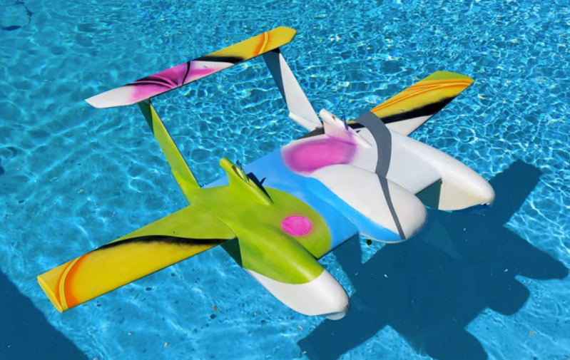
This build from [Think Flight] started off as a simple foam model of just such a ground effect vehicle (or “ekranoplan”) in his driveway. With a few test flights the model was refined enough to attach a small propeller and battery. The location of the propeller changed from rear-mounted to front-mounted and then back to rear-mounted for the final version, with each configuration having different advantages and disadvantages. The final model includes an Arudino running an autopilot program called Ardupilot, and with an air speed sensor installed the drone is able to maintain flight in the ground effect and autonomously navigate pre-programmed waypoints around a lake at high speed.

For a Cold War technology that’s been largely abandoned by militaries in favor of other modes of transportation due to its limited use case and extremely narrow flight tolerances, ground effect vehicles are relatively popular as remote controlled vehicles. This RC ekranoplan used the same Ardupilot software but paired with a LIDAR system instead of GPS to navigate its way around its environment.

Thanks to [TTN] for the tip!

Custom Strain Gauges Help Keep Paraglider Aloft

No matter what they’re flying, good pilots have a “feel” for their aircraft. They know instantly when something is wrong, whether by hearing a strange sound or a feeling a telltale vibration. Developing this sixth sense is sometimes critical to the goal of keeping the number of takeoff equal to the number of landings.

The same thing goes for non-traditional aircraft, like paragliders, where the penalty for failure is just as high. Staying out of trouble aloft is the idea behind this paraglider line tension monitor designed by pilot [Andre Bandarra]. Paragliders, along with their powered cousins paramotors, look somewhat like parachutes but are actually best described as an inflatable wing. The wing maintains its shape by being pressurized by air coming through openings in the leading edge. If the pilot doesn’t maintain the correct angle of attack, the wing can depressurize and collapse, with sometimes dire results.

Luckily, most pilots eventually develop a feel for collapse, sensed through changes in the tension of the lines connecting the wing to his or her harness. [Andre]’s “Tensy” — with the obligatory “McTenseface” surname — that’s featured in the video below uses an array of strain gauges to watch to the telltale release of tension in the lines for the leading edge of the wing, sounding an audible alarm. As a bonus, Tensy captures line tension data from across the wing, which can be used to monitor the performance of both the aircraft and the pilot.

There are a lot of great design elements here, but for our money, we found the lightweight homebrew strain gauges to be the real gem of this design. This isn’t the first time [Andre] has flown onto these pages, either — his giant RC paraglider was a big hit back in January.

Thanks to [mip] for the tip.

Flight Suit Review

Since building my Flight Suit last year, I haven't posted many photos or videos of the finished suit or of its inner workings, so I will make a series of posts about it over the next few weeks. I would not have been able to complete the project without the generous sharing of the OSHW community, and I hope some bit of my project's details will be of some use to somebody.

All work on the suit revolved around a composite image I put together early to lay out the LED light strips, with each level numbered (0-11) and each segment getting a unique letter designation (A-X). Arms are shown up and down since the suit adapts to the arms' positions, lighting up each segment according to its current level.

From that composite image, I built a segment spreadsheet to keep track of the 22 LED strips through construction and programming. It includes all of the segments' lengths and progress steps, plus designations of levels, segment letters, and channels.

The system's electronic components are distributed throughout the suit using existing fittings on the suit when possible:
  • The 12V Li-ion battery pack which powers the suit fits nicely in the right thigh pocket.  Its switch acts as the main system on/off switch.  Spare battery packs fit in zippered ankle pockets.
  • The main system board sits in the upper left arm pocket: an Arduino-compatible board with a shield containing the left arm accelerometer board and jacks for the right arm accelerometer, MOSFET boards, ZX-Sound, and remote control.
  • The right arm accelerometer sits in a small pocket sewed onto the right upper arm.
  • MOSFET boards hang in the chest pockets, attached to the leads routed through the suit to the LED strips.
  • The ZX-Sound audio board is mounted with Velcro to the included patch on the left chest.
  • The remote control dangles from its cat 5 cable or attaches to an existing Velcro strip at the waist.
I plan to post at least once on each of these topics:
  • System layout, schematics and final firmware
  • LED strips: planning, splitting/making, mounting
  • MOSFET boards: driving the LED strips
  • ZX-Sound: incorporating audio response into the system
  • Arm accelerometers: reading and filtering and controlling segment/level mapping
  • Remote control
  • Main program design: fast looping, modes, ShiftPWM
  • Wearability: marrying the system and the suit, sewing, gluing, maintenance
If there's something else you're curious about, please email me or post a comment. As I post more, I will continue to upload photos to my Flickr set.
Jeff's Arduino Blog 01 May 20:03
flight  suit  

DARPA's crowdsourced UAV competition heats up, takes off (video)

Late last year, DARPA launched UAVForge -- a competition that invites contestants to create their very own unmanned aerial vehicles, and submit them for voter-based evaluation. The project is far from over, but competing teams have already started sending in their proof-of-flight videos, giving us a glimpse of what's to come. So far, it looks like the GremLion UAV (pictured above) is the early favorite, after coming out victorious in the first round of voting. Developed by a team from the National University of Singapore, the GremLion looks like a bite-sized Death Star and flies around using a coaxial set of rotors that expand tulip-style out of its shell. Also included in the UAVForge showdown is a guy known as X-MAUS -- an Arduino-controlled quadcopter that can apparently transform into a more aerodynamic plane form upon liftoff. And, rounding out the list of notables is a submission from TU Delft known as the QuadShot, which is basically a miniature B-Wing from Star Wars. Except it's real. Hit up the break to see all three in action.

Continue reading DARPA's crowdsourced UAV competition heats up, takes off (video)

DARPA's crowdsourced UAV competition heats up, takes off (video) originally appeared on Engadget on Wed, 08 Feb 2012 04:58:00 EST. Please see our terms for use of feeds.

Permalink | Email this | Comments

(F)Light Suit Progress: Almost There!

So much progress in the last two weeks, the big milestones being...
  • I got the MOSFET boards and built three-- they worked right away! As expected I needed resistors between the 595 outputs and the MOSFETs; didn't notice that until I hooked up the third one and things weren't behaving. I'm not crazy about the screw terminals but they'll be OK.
  • Testing the MOSFET outputs with all 22 segments-- 53' of light, so bright! The first tests were just "All Fade" mode.
  • Expanding the program to sense arm angles. The routine automatically sets arm levels, either up/down or matching angle, and how many levels there are (since arms up can create a new level).
  • Adding a proper "Rolling" mode to sweep a band or bands over the whole suit, top to bottom, with variables delay (ms), brightness, direction, and number of bands (density). Seeing all the bands rolling through was a relief.
  • Sewing is awesome. I've sewn 10 out of 19 "loop" side Velcro bands into the suit: both legs and the hips and waist.
  • ZX-Sound works! Filtering and sampling will be the last things I dial in, but I have working bouncy light code, smoothed and at whatever Hz I want, dynamically computing the high and low so it will bounce if it's quiet or loud.
Still big items:
  • Integrate audio sketch into main line, finish filtering code, and use filtering code for gravity sketch,
  • Finish sewing hook-side Velcro strips onto the suit,
  • Cut the loop-side Velcro for the light strips and stick it on with silicone,
  • Measure and cut and route in-suit leads: 4 solder points each, 6 pieces of shrink,
  • Sew in conduit for left-to-right board, battery, audio, and accelerometer leads.
  • Address shoes, hat(s), headband mounting and routing...
That's all I can think of for now, back to sewing...
Jeff's Arduino Blog 25 Aug 04:43
flight  suit