Learn how to use the NXP PCF 8591 8-bit A/D and D/A IC with Arduino in chapter fifty-two of my Arduino Tutorials. The first chapter is here, the complete series is detailed here.
Updated 17/06/2013
Introduction
Have you ever wanted more analogue input pins on your Arduino project, but not wanted to fork out for a Mega? Or would you like to generate analogue signals? Then check out the subject of our tutorial – the NXP PCF8591 IC. It solves both these problems as it has a single DAC (digital to analogue) converter as well as four ADCs (analogue to digital converters) – all accessible via the I2C bus. If the I2C bus is new to you, please familiarise yourself with the readings here before moving forward.
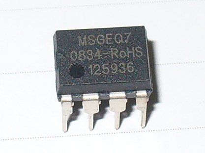
The PCF8591 is available in DIP form, which makes it easy to experiment with:
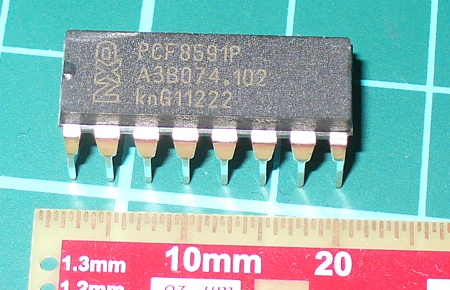
You can get them from the usual retailers. Before moving on, download the data sheet. The PCF8591 can operate on both 5V and 3.3V so if you’re using an Arduino Due, Raspberry Pi or other 3.3 V development board you’re fine. Now we’ll first explain the DAC, then the ADCs.
Using the DAC (digital-to-analogue converter)
The DAC on the PCF8591 has a resolution of 8-bits – so it can generate a theoretical signal of between zero volts and the reference voltage (Vref) in 255 steps. For demonstration purposes we’ll use a Vref of 5V, and you can use a lower Vref such as 3.3V or whatever you wish the maximum value to be … however it must be less than the supply voltage. Note that when there is a load on the analogue output (a real-world situation), the maximum output voltage will drop – the data sheet (which you downloaded) shows a 10% drop for a 10kΩ load. Now for our demonstration circuit:
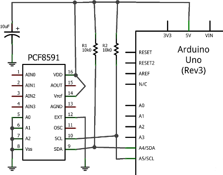
Note the use of 10kΩ pull-up resistors on the I2C bus, and the 10μF capacitor between 5V and GND. The I2C bus address is set by a combination of pins A0~A2, and with them all to GND the address is 0x90. The analogue output can be taken from pin 15 (and there’s a seperate analogue GND on pin 13. Also, connect pin 13 to GND, and circuit GND to Arduino GND.
To control the DAC we need to send two bytes of data. The first is the control byte, which simply activates the DAC and is 1000000 (or 0x40) and the next byte is the value between 0 and 255 (the output level). This is demonstrated in the following sketch:
// Example 52.1 PCF8591 DAC demo
// http://tronixstuff.com/tutorials Chapter 52
// John Boxall June 2013
#include "Wire.h"
#define PCF8591 (0x90 >> 1) // I2C bus address
void setup()
{
 Wire.begin();
}
void loop()
{
 for (int i=0; i<256; i++)
 {
 Wire.beginTransmission(PCF8591); // wake up PCF8591
 Wire.write(0x40); // control byte - turn on DAC (binary 1000000)
 Wire.write(i); // value to send to DAC
 Wire.endTransmission(); // end tranmission
 }

 for (int i=255; i>=0; --i)
 {
 Wire.beginTransmission(PCF8591); // wake up PCF8591
 Wire.write(0x40); // control byte - turn on DAC (binary 1000000)
 Wire.write(i); // value to send to DAC
 Wire.endTransmission(); // end tranmission
 }
}
Did you notice the bit shift of the bus address in the #define statement? Arduino sends 7-bit addresses but the PCF8591 wants an 8-bit, so we shift the byte over by one bit.
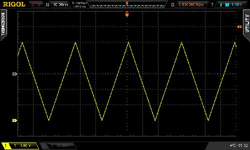
The results of the sketch are shown below, we’ve connected the Vref to 5V and the oscilloscope probe and GND to the analogue output and GND respectively:
If you like curves you can generate sine waves with the sketch below. It uses a lookup table in an array which contains the necessary pre-calculated data points:
// Example 52.2 PCF8591 DAC demo - sine wave
// http://tronixstuff.com/tutorials Chapter 52
// John Boxall June 2013
#include "Wire.h"
#define PCF8591 (0x90 >> 1) // I2C bus address
uint8_t sine_wave[256] = {
0x80, 0x83, 0x86, 0x89, 0x8C, 0x90, 0x93, 0x96,
0x99, 0x9C, 0x9F, 0xA2, 0xA5, 0xA8, 0xAB, 0xAE,
0xB1, 0xB3, 0xB6, 0xB9, 0xBC, 0xBF, 0xC1, 0xC4,
0xC7, 0xC9, 0xCC, 0xCE, 0xD1, 0xD3, 0xD5, 0xD8,
0xDA, 0xDC, 0xDE, 0xE0, 0xE2, 0xE4, 0xE6, 0xE8,
0xEA, 0xEB, 0xED, 0xEF, 0xF0, 0xF1, 0xF3, 0xF4,
0xF5, 0xF6, 0xF8, 0xF9, 0xFA, 0xFA, 0xFB, 0xFC,
0xFD, 0xFD, 0xFE, 0xFE, 0xFE, 0xFF, 0xFF, 0xFF,
0xFF, 0xFF, 0xFF, 0xFF, 0xFE, 0xFE, 0xFE, 0xFD,
0xFD, 0xFC, 0xFB, 0xFA, 0xFA, 0xF9, 0xF8, 0xF6,
0xF5, 0xF4, 0xF3, 0xF1, 0xF0, 0xEF, 0xED, 0xEB,
0xEA, 0xE8, 0xE6, 0xE4, 0xE2, 0xE0, 0xDE, 0xDC,
0xDA, 0xD8, 0xD5, 0xD3, 0xD1, 0xCE, 0xCC, 0xC9,
0xC7, 0xC4, 0xC1, 0xBF, 0xBC, 0xB9, 0xB6, 0xB3,
0xB1, 0xAE, 0xAB, 0xA8, 0xA5, 0xA2, 0x9F, 0x9C,
0x99, 0x96, 0x93, 0x90, 0x8C, 0x89, 0x86, 0x83,
0x80, 0x7D, 0x7A, 0x77, 0x74, 0x70, 0x6D, 0x6A,
0x67, 0x64, 0x61, 0x5E, 0x5B, 0x58, 0x55, 0x52,
0x4F, 0x4D, 0x4A, 0x47, 0x44, 0x41, 0x3F, 0x3C,
0x39, 0x37, 0x34, 0x32, 0x2F, 0x2D, 0x2B, 0x28,
0x26, 0x24, 0x22, 0x20, 0x1E, 0x1C, 0x1A, 0x18,
0x16, 0x15, 0x13, 0x11, 0x10, 0x0F, 0x0D, 0x0C,
0x0B, 0x0A, 0x08, 0x07, 0x06, 0x06, 0x05, 0x04,
0x03, 0x03, 0x02, 0x02, 0x02, 0x01, 0x01, 0x01,
0x01, 0x01, 0x01, 0x01, 0x02, 0x02, 0x02, 0x03,
0x03, 0x04, 0x05, 0x06, 0x06, 0x07, 0x08, 0x0A,
0x0B, 0x0C, 0x0D, 0x0F, 0x10, 0x11, 0x13, 0x15,
0x16, 0x18, 0x1A, 0x1C, 0x1E, 0x20, 0x22, 0x24,
0x26, 0x28, 0x2B, 0x2D, 0x2F, 0x32, 0x34, 0x37,
0x39, 0x3C, 0x3F, 0x41, 0x44, 0x47, 0x4A, 0x4D,
0x4F, 0x52, 0x55, 0x58, 0x5B, 0x5E, 0x61, 0x64,
0x67, 0x6A, 0x6D, 0x70, 0x74, 0x77, 0x7A, 0x7D
};
void setup()
{
Wire.begin();
}
void loop()
{
for (int i=0; i<256; i++)
{
Wire.beginTransmission(PCF8591); // wake up PCF8591
Wire.write(0x40); // control byte - turn on DAC (binary 1000000)
Wire.write(sine_wave[i]); // value to send to DAC
Wire.endTransmission(); // end tranmission
}
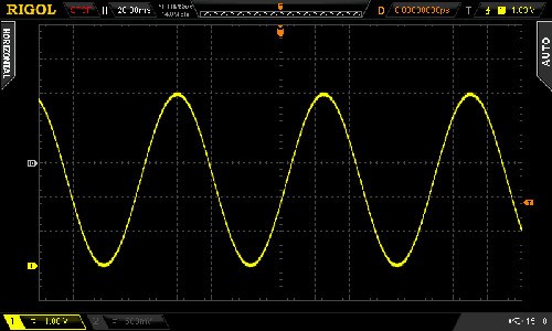
}And the results:
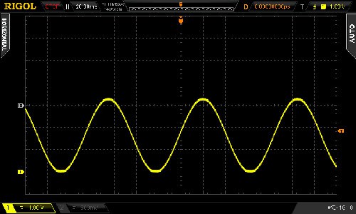
For the following DSO image dump, we changed the Vref to 3.3V – note the change in the maxima on the sine wave:
Now you can experiment with the DAC to make sound effects, signals or control other analogue circuits.
Using the ADCs (analogue-to-digital converters)
If you’ve used the analogRead() function on your Arduino (way back in Chapter One) then you’re already familiar with an ADC. With out PCF8591 we can read a voltage between zero and the Vref and it will return a value of between zero and 255 which is directly proportional to zero and the Vref. For example, measuring 3.3V should return 168. The resolution (8-bit) of the ADC is lower than the onboard Arduino (10-bit) however the PCF8591 can do something the Arduino’s ADC cannot. But we’ll get to that in a moment.
First, to simply read the values of each ADC pin we send a control byte to tell the PCF8591 which ADC we want to read. For ADCs zero to three the control byte is 0x00, 0x01, ox02 and 0x03 respectively. Then we ask for two bytes of data back from the ADC, and store the second byte for use. Why two bytes? The PCF8591 returns the previously measured value first – then the current byte. (See Figure 8 in the data sheet). Finally, if you’re not using all the ADC pins, connect the unused ones to GND.
The following example sketch simply retrieves values from each ADC pin one at a time, then displays them in the serial monitor:
// Example 52.3 PCF8591 ADC demo
// http://tronixstuff.com/tutorials Chapter 52
// John Boxall June 2013
#include "Wire.h"
#define PCF8591 (0x90 >> 1) // I2C bus address
#define ADC0 0x00 // control bytes for reading individual ADCs
#define ADC1 0x01
#define ADC2 0x02
#define ADC3 0x03
byte value0, value1, value2, value3;
void setup()
{
 Wire.begin();
 Serial.begin(9600);
}
void loop()
{
 Wire.beginTransmission(PCF8591); // wake up PCF8591
 Wire.write(ADC0); // control byte - read ADC0
 Wire.endTransmission(); // end tranmission
 Wire.requestFrom(PCF8591, 2);
 value0=Wire.read();
 value0=Wire.read();
 Wire.beginTransmission(PCF8591); // wake up PCF8591
 Wire.write(ADC1); // control byte - read ADC1
 Wire.endTransmission(); // end tranmission
 Wire.requestFrom(PCF8591, 2);
 value1=Wire.read();
 value1=Wire.read();
 Wire.beginTransmission(PCF8591); // wake up PCF8591
 Wire.write(ADC2); // control byte - read ADC2
 Wire.endTransmission(); // end tranmission
 Wire.requestFrom(PCF8591, 2);
 value2=Wire.read();
 value2=Wire.read();
 Wire.beginTransmission(PCF8591); // wake up PCF8591
 Wire.write(ADC3); // control byte - read ADC3
 Wire.endTransmission(); // end tranmission
 Wire.requestFrom(PCF8591, 2);
 value3=Wire.read();
 value3=Wire.read();
 Serial.print(value0); Serial.print(" ");
 Serial.print(value1); Serial.print(" ");
 Serial.print(value2); Serial.print(" ");
 Serial.print(value3); Serial.print(" ");
 Serial.println();
}
Upon running the sketch you’ll be presented with the values of each ADC in the serial monitor. Although it was a simple demonstration to show you how to individually read each ADC, it is a cumbersome method of getting more than one byte at a time from a particular ADC.
To do this, change the control byte to request auto-increment, which is done by setting bit 2 of the control byte to 1. So to start from ADC0 we use a new control byte of binary 00000100 or hexadecimal 0x04. Then request five bytes of data (once again we ignore the first byte) which will cause the PCF8591 to return all values in one chain of bytes. This process is demonstrated in the following sketch:
// Example 52.4 PCF8591 ADC demo
// http://tronixstuff.com/tutorials Chapter 52
// John Boxall June 2013
#include "Wire.h"
#define PCF8591 (0x90 >> 1) // I2C bus address
byte value0, value1, value2, value3;
void setup()
{
 Wire.begin();
 Serial.begin(9600);
}
void loop()
{
 Wire.beginTransmission(PCF8591); // wake up PCF8591
 Wire.write(0x04); // control byte - read ADC0 then auto-increment
 Wire.endTransmission(); // end tranmission
 Wire.requestFrom(PCF8591, 5);
 value0=Wire.read();
 value0=Wire.read();
 value1=Wire.read();
 value2=Wire.read();
 value3=Wire.read();
 Serial.print(value0); Serial.print(" ");
 Serial.print(value1); Serial.print(" ");
 Serial.print(value2); Serial.print(" ");
 Serial.print(value3); Serial.print(" ");
 Serial.println();
}
Previously we mentioned that the PCF8591 can do something that the Arduino’s ADC cannot, and this is offer a differential ADC. As opposed to the Arduino’s single-ended (i.e. it returns the difference between the positive signal voltage and GND, the differential ADC accepts two signals (that don’t necessarily have to be referenced to ground), and returns the difference between the two signals. This can be convenient for measuring small changes in voltages for load cells and so on.
Setting up the PCF8591 for differential ADC is a simple matter of changing the control byte. If you turn to page seven of the data sheet, then consider the different types of analogue input programming. Previously we used mode ’00’ for four inputs, however you can select the others which are clearly illustrated, for example:
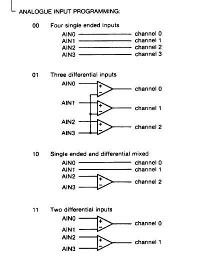
So to set the control byte for two differential inputs, use binary 00110000 or 0x30. Then it’s a simple matter of requesting the bytes of data and working with them. As you can see there’s also combination single/differential and a complex three-differential input. However we’ll leave them for the time being.
Conclusion
Hopefully you found this of interest, whether adding a DAC to your experiments or learning a bit more about ADCs. We’ll have some more analogue to digital articles coming up soon, so stay tuned. And if you enjoy my tutorials, or want to introduce someone else to the interesting world of Arduino – check out my new book “Arduino Workshop” from No Starch Press.

In the meanwhile have fun and keep checking into tronixstuff.com. Why not follow things on twitter, Google+, subscribe for email updates or RSS using the links on the right-hand column? And join our friendly Google Group – dedicated to the projects and related items on this website. Sign up – it’s free, helpful to each other – and we can all learn something.
The post Tutorial – Arduino and PCF8591 ADC DAC IC appeared first on tronixstuff.