1
2
3
4
5
6
7
8
9
10
11
12
13
14
15
16
17
18
19
20
21
22
23
24
25
26
27
28
29
30
31
32
33
34
35
36
37
38
39
40
41
42
43
44
45
46
47
48
49
50
51
52
53
54
55
56
57
58
59
60
61
62
63
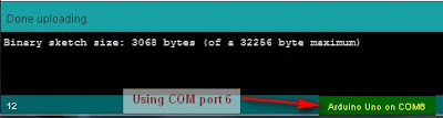
64 | /* Simple Serial ECHO script : Written by ScottC 05/07/2012 */
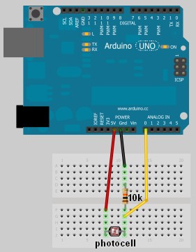
/* Stage 3: Arduino Maths: Simple Addition */
/* Global variables needed for programming workflow
byteRead: holds the value being read from the COM port
num1: holds the entire first number
num2: holds the entire second number
answer: holds the sum of num1 and num2
mySwitch: enables the switch between num1 and num2 */
byte byteRead;
long num1, num2,answer;
boolean mySwitch=false;
void setup() {
/* Turn the Serial Protocol ON and
initialise num1 and num2 variables.*/
Serial.begin(9600);
num1=0;
num2=0;
}
void loop() {
/* check if data has been sent from the computer: */
while (Serial.available()) {
/* read the most recent byte */
byteRead = Serial.read();
//listen for numbers between 0-9
if(byteRead>47 && byteRead<58){
//number found
/* If mySwitch is true, then populate the num1 variable
otherwise populate the num2 variable*/
if<!mySwitch)><br /> num1=(num1*10)+(byteRead-48);<br /> }<span>else</span>{<br /> num2=(num2*10)+(byteRead-48);<br /> }<br /> }<br /> <br /> <span>/*Listen for an equal sign (byte code 61) </span><br /><span> to calculate the answer and send it back to the</span><br /><span> serial monitor screen*/</span><br /> <span>if</span>(byteRead==61){<br /> answer=num1+num2;<br /> Serial.print(num1);<br /> Serial.print(<span>"+"</span>);<br /> Serial.print(num2);<br /> Serial.print(<span>"="</span>);<br /> Serial.println(answer);<br /> <br /> <span>/* Reset the variables for the next round */</span><br /> num1=0;<br /> num2=0;<br /> mySwitch=<span>false</span>;<br /> <br /> <span>/* Listen for the addition sign (byte code 43). This is</span><br /><span> used as a delimiter to help define num1 from num2 */</span> <br /> }<span>else</span> <span>if</span> (byteRead==43){<br /> mySwitch=<span>true</span>;<br /> }<br /> }<br />}<br /></pre></td></tr></tbody></table></div><br /><span>The above code was formatted using <a href="http://hilite.me/">this site</a></span><br /><br /><br /><h3> <u>Instructions</u></h3><br /><b>1.</b> Once the code has been uploaded to the Arduino, open the Serial Monitor once again and type the following sequence:<br /><br /> <span>1+2= <enter></span><br /><br />You should get the following message sent back to Serial Monitor<br /><br /> <span> 1+2=3</span><br /><br /><br /><br /><h3> <b><u>Things to Try</u></b></h3><b>1.</b> Enter this sequence: <br /> <span>10 <enter></span><br /><span> + <enter></span><br /><span> 10 <enter></span><br /><span> = <enter></span><br /><br /> Result: <span>10+10=20</span><br /><br /><span>--------------------------------------------------------------------</span><br /><b>2. </b> Enter this sequence:<br /> <span> 10 <enter></span><br /><span> 20 <enter></span><br /><span> +5= <enter></span><br /><br /><br /> Result: <span> 1020+5=1025</span><br /><br /><br /><br /><br /><span>--------------------------------------------------------------------</span><br /><b>3.</b> Enter this sequence:<br /> <span> 10+20+30= <enter></span><br /><br /><br /> Result: <span>10+2030=2040</span><br /><br />I have specifically written this script to add <b>two</b> whole numbers together. If you start to introduce more complicated calculations, the results become unpredictable.<br /><br /><span>--------------------------------------------------------------------</span><br /><b>4.</b> Enter this sequence:<br /> <span>1.2+1.0= <enter></span><br /><br /> Result: <span>12+10=22</span><br /><br />Once again, I have only designed this script to handle whole numbers. Therefore, decimal points are ignored.<br /><br /><span>--------------------------------------------------------------------</span><br /><b>5.</b> Enter this sequence:<br /> <span> -5 + 10= <enter></span><br /><br /><br /> Result: <span>5+10=15</span><br /><br /><br />This script ignores the negative sign, and treats the -5 as a positive 5.<br /><br /><br /><div>I have done this on purpose. I wanted to show you how the Arduino reads numbers from the com port, and how easy it is to exclude vital functionality in your code. I have kept this script simple, however, if you wanted to, you could make the Arduino deal with each of the above situations and more. Multiplication, division and subtraction is handled in the same way. </div><br />This is the last thing I want you to try before we go to the next stage:<br /><br />6. Enter this sequence:<br /> <span>2147483646+1= <enter></span> Result: <span>2147483646+1=2147483647</span><br /> <span> 2147483647+1= <enter></span> Result: <span>2147483647+1=</span><span>-</span><span>2147483648</span><br /><br /><br />Note that the maximum size of a "long" number is 2147483647. If you add one to this number, the result is equal to the minimum size of a "long" which is -2147483648.<br /><br /><br /><br /><br /><h3> <b><span><span>STAGE 4: Sending doubles to Arduino</span> : <span>The double doubler</span> </span></b></h3><div>Now we get to some tricky business. Sending and receiving Doubles (to and from) the Arduino.<br /><br />Up until now, I have tried to keep it simple using whole numbers, but there will come a time when you will want to send a fraction of a number through the Serial line.</div><div>To test our program, we will want to send a very small number to the Arduino, multiply the number by 2, and return it back.</div><div><br /></div><div>Our final test is to try a number like : <b>0.000001</b></div><div> and then a number like:<b> 123.321</b></div><div><br /></div><div><br /><b><span>IMPORTANT NOTE</span></b>: When the Arduino sends a float or a double through the COM port using Serial.print() or Serial.println(), it will automatically send the number to 2 decimal places.<br />A number like 1.2345 will appear as 1.23, and a number like 1.9996 will appear as 2.00<br />To demonstrate this, we will get the Arduino to send these floats/doubles to the Serial Monitor.<br /><br /><br /><div>Enter the following sketch into your Arduino IDE and upload it to your Arduino.</div><div><br /></div><h3> <u>Arduino Sketch</u></h3><br /><div><table><tbody><tr><td><pre><span><span> 1<br /> 2<br /> 3<br /> 4<br /> 5<br /> 6<br /> 7<br /> 8<br /> 9<br />10<br />11<br />12<br />13<br />14<br />15<br />16<br />17<br />18<br />19<br />20<br />21<br />22<br />23<br />24<br />25<br />26<br />27<br />28</span></span></pre></td><td><pre><span>/* Stage 4: Simple Transmission of a Double</span><br /><span> Written by ScottC on 7/7/2012 */</span><br /><br /><span>/* Declare the doubles that will be sent to the Serial Monitor */</span><br /> <span>double</span> myDub1, myDub2;<br /><br /><span>/* This part of the program only runs ONCE */</span><br /><br /> <span>void</span> setup(){<br /><br /> <span>/* Turn ON Serial Communication */</span><br /> Serial.begin(9600);<br /> <br /> <span>/* Assign a value 1.2345 and 1.9996 to the Doubles being sent */</span><br /> myDub1=1.2345;<br /> myDub2=1.9996;<br /> <br /> <span>/*Send the values to the Serial Monitor */</span><br /> Serial.print(<span>"myDub1 (1.2345) : "</span>);<br /> Serial.println(myDub1);<br /> Serial.print(<span>"myDub2 (1.9996) : "</span>);<br /> Serial.println(myDub2);<br /> }<br /><br /><br /> <span>void</span> loop(){<br /> <span>//Loop does nothing</span><br /> }<br /></pre></td></tr></tbody></table></div><span>The above code was formatted using </span><a href="http://hilite.me/">this site</a><br /><br />When you open the Serial monitor (after you have uploaded the sketch above), you will notice the following output:<br /><br /><br /> <span> myDub1 (1.2345) :</span> <span>1.23</span><br /> <span> myDub2 (1.9996) :</span> <span>2.00</span><br /><div><br /></div><br /><br />The <span>blue text</span> represents the string (or array of characters) being sent using lines 19 and 21.<br />The <span>red text</span> represents the actual double being sent using lines 20 and 22.<br /><br />You will notice that myDub2 rounds to 2.00. This may or may not be what you want.<br />If you wish to increase the number of decimal places, then you will need to change lines 20 and 22 to the following:<br /><br /><span><span>20 Serial.println(myDub1,</span><span>4</span><span>)</span>;</span><br /><span><span>22 Serial.println(myDub2,</span><span>4</span><span>);</span></span><br /><br />The number 4 highlighted in red, indicates the number of decimal places you wish to send.<br />Try it ! And try changing this number to something bigger or smaller.<br /><br />---------------------------------------------------------------------------------------------------<br />Ok - now that we understand this little Serial.print(double,decimals) trick, we will now get the Arduino to echo back a Double.<br /><br />Before we jump in, perhaps we should try and map out our strategy. For this we will choose a simple decimal to make it easier. So in this example, we will choose <b>0.1</b></div><div>Once we get this working, we can then do our final test (as mentioned above).</div><div><br /></div><div>If we send 0.1 to the Arduino, it will read the following byte code</div><div><br /></div><div>48 0</div><div>46 .</div><div>49 1</div><div><br /></div><div>We can use the decimal point as a delimiter.<br />We will use the following 5 steps to echo the double back to the Serial Monitor:</div><div><br /></div><div><b><span>Step1</span>:</b> Arduino collects all numbers before the decimal point using the same technique as in Stage3.<br /><br /></div><div><b><span>Step2</span>: </b>When the Arduino receives byte code 46, it will go into decimal mode.<br /><br /></div><div><b><span>Step3</span>:</b> The Arduino will collect numbers after the decimal point using a similar technique to step1.<br /><br /></div><div><b><span>Step4</span>:</b> Use maths to create the double, and then multiply it by 2<br /><br /></div><div><b><span>Step5</span>:</b> Display the doubled Double value in the Serial monitor.</div><div><br /></div><div><br /></div><div><br /><div>Enter the following sketch into your Arduino IDE and upload it to your Arduino.</div><div><br /></div><h3> <u>Arduino Sketch</u></h3></div><div><br /></div><div><table><tbody><tr><td><pre><span><span> 1<br /> 2<br /> 3<br /> 4<br /> 5<br /> 6<br /> 7<br /> 8<br /> 9<br />10<br />11<br />12<br />13<br />14<br />15<br />16<br />17<br />18<br />19<br />20<br />21<br />22<br />23<br />24<br />25<br />26<br />27<br />28<br />29<br />30<br />31<br />32<br />33<br />34<br />35<br />36<br />37<br />38<br />39<br />40<br />41<br />42<br />43<br />44<br />45<br />46<br />47<br />48<br />49<br />50<br />51<br />52<br />53<br />54<br />55<br />56<br />57<br />58<br />59<br />60<br />61<br />62<br />63<br />64<br />65<br />66<br />67<br />68<br />69<br />70<br />71<br />72<br />73<br />74<br />75<br />76<br />77<br />78<br />79<br />80<br />81<br />82<br />83<br />84<br />85</span></span></pre></td><td><pre><span>/* Simple Serial ECHO script : Written by ScottC 06/07/2012 */</span><br /><span>/* Stage 4: Double doubler */</span><br /><br /><span>/* Global variables needed for programming workflow</span><br /><span> ------------------------------------------------------</span><br /><span> byteRead: holds the value being read from the COM port</span><br /><span> num1: holds the number before the decimal point</span><br /><span> num2: holds the number after the decimal point</span><br /><span> complNum: holds the complete number (before multiplation)</span><br /><span> answer: holds the final value after multiplication</span><br /><span> counter: is used to convert num2 to the number after the decimal</span><br /><span> numOfDec: counts the numbers after the decimal point</span><br /><span> mySwitch: enables the switch between num1 and num2 */</span><br /> <br /> byte byteRead;<br /> <span>double</span> num1, num2;<br /> <span>double</span> complNum,answer,counter;<br /> <span>int</span> numOfDec;<br /> boolean mySwitch=<span>false</span>;<br /><br /><br /> <span>void</span> setup() { <br /><span>/* Turn the Serial Protocol ON and </span><br /><span> initialise num1 and num2 variables.*/</span><br /> Serial.begin(9600);<br /> num1=0;<br /> num2=0;<br /> complNum=0;<br /> counter=1;<br /> numOfDec=0;<br /> }<br /><br /> <span>void</span> loop() {<br /><span>/* check if data has been sent from the computer: */</span><br /> <span>while</span> (Serial.available()) {<br /> <span>/* read the most recent byte */</span><br /> byteRead = Serial.read();<br /> <br /> <span>//listen for numbers between 0-9</span><br /> <span>if</span>(byteRead>47 && byteRead<58){<br /> <span>//number found</span><br /> <br /> <span>/* If mySwitch is true, then populate the num1 variable</span><br /><span> otherwise populate the num2 variable*/</span><br /> <span>if</span><!mySwitch)><br /> num1=(num1*10)+(byteRead-48);<br /> }<span>else</span>{<br /> num2=(num2*10)+(byteRead-48);<br /> <br /> <span>/* These counters are important */</span><br /> counter=counter*10;<br /> numOfDec++;<br /> }<br /> }<br /> <br /> <span>/*Listen for an equal sign (byte code 61) </span><br /><span> to calculate the answer and send it back to the</span><br /><span> serial monitor screen*/</span><br /> <span>if</span>(byteRead==61){<br /> <span>/* Create the double from num1 and num2 */</span><br /> complNum=num1+(num2/(counter));<br /> <br /> <span>/* Multiply the double by 2 */</span> <br /> answer=complNum*2;<br /> <br /> <span>/* Send the result to the Serial Monitor */</span> <br /> Serial.print(complNum,numOfDec);<br /> Serial.print(<span>" x 2 = "</span>);<br /> Serial.println(answer,numOfDec);<br /> <br /> <span>/* Reset the variables for the next round */</span><br /> num1=0;<br /> num2=0;<br /> complNum=0;<br /> counter=1;<br /> mySwitch=<span>false</span>;<br /> numOfDec=0;<br /> <br /> <span>/* Listen for the decimal point (byte code 46). This is</span><br /><span> used as a delimiter to help define num1 from num2 */</span> <br /> }<span>else</span> <span>if</span> (byteRead==46){<br /> mySwitch=<span>true</span>;<br /> }<br /> }<br /> }<br /></pre></td></tr></tbody></table></div><div><span>The above code was formatted using </span><a href="http://hilite.me/">this site</a></div><div><br /></div><div><br /></div><div><br /><h3> <b><u>Things to Try</u></b></h3><div><b><u><br /></u></b></div><div>1. Type the following into the serial monitor:</div><div><br /></div><div> <span>1.2= <enter></span> Result: <span>1.2 x 2 = 2.4</span></div><div><br /></div><div>Make sure that you type the equal sign (=) before you press enter, otherwise the Arduino will not know that you are finished, and will not send anything back.</div><div><br /></div><div>--------------------------------------------------------------------</div><div>2. Type the following into the serial monitor:</div><div><br /></div><div> <span>100.001= <enter></span> Result: <span>100.001 x 2 = 200.002</span></div><div><br /></div><div>You will notice that the Arduino is formatting the decimal to the SAME number of decimals as that entered.</div><div>This is controlled by the variable: <span>numOfDec</span>.</div><div>---------------------------------------------------------------------</div><div>3. Now for our final test: Type the following into the serial monitor:</div><div><br /></div><div> <span> 0.000001= <enter></span> Result: <span>0.000001 x 2 = 0.000002</span></div><div><br /></div><div>First test:<span> PASSED</span></div><div><br /></div><div>----------------------------------------------------------------------</div><div>4. Type the following into the Serial monitor for our last test:</div><div><br /></div><div> <span>123.321= <enter></span> Result: <span>123.321 x 2 = 246.642</span></div><div><br /></div><div>Second test: <span>PASSED</span></div><div>-----------------------------------------------------------------------</div><div><br /></div><div><span>BEWARE</span>: While everything looks perfect, let me tell you that it isn't. But hopefully this code will help you get on the right track. If you decide to type in a number like 123123.111222, you will not get the answer you expected. </div><div>I have found that this program will work if the amount of numbers before and after the decimal point are less than about 9. Eg. 1234.1234 will produce the right result.</div><div>However, 11111.2222 will NOT, because there are 9 numbers represented.</div><div><br /></div><div>I think this has something to do with the memory allocated to a double, but I am not sure. </div><div>I don't know if people work with these types of numbers, but I am sure there is a workaround, and I am sure someone out there can work it out. I don't personally need this kind of precision, but thought to mention it just in case you do.</div><div><br /></div><div><br />----------------------------------------------------------------------- <br />----------------------------------------------------------------------- <br /><br /><h3> <b><span><span>STAGE 5: Sending sensor data to the Serial Monitor</span> </span></b></h3><br /><br />We know the Arduino is very good at copy-Cat games, how about getting the Arduino to send us some data from one of our sensors. We will use the Serial Monitor to view the sensor data.<br /><br />Disconnect the USB cable, and hook up one of your favourite analog sensors to your Arduino. For simplicity, I am going to hook up a potentiometer as per the Fritzing sketch below.<br /><br /><h3> <u> Parts Required</u></h3><br /><ul><li>Arduino UNO (or equivalent)</li><li>Computer with USB cable</li><li>Breadboard</li><li>Potentiometer</li><li>3 Wires</li></ul><div><br /></div><br /><h3> <u> Arduino Fritzing Sketch</u></h3><br /></div><div><div><a href="http://1.bp.blogspot.com/-JZlWUi3MDck/T_g6ldkqSVI/AAAAAAAAAPY/_UJj4EU3YYE/s1600/Fritzing_Potentiometer_Sketch.jpg"><img src="http://1.bp.blogspot.com/-JZlWUi3MDck/T_g6ldkqSVI/AAAAAAAAAPY/_UJj4EU3YYE/s400/Fritzing_Potentiometer_Sketch.jpg" /></a></div><br /></div><div><br /></div><div> </div><div><br /></div><div><br /></div></div><br /><br /><br /><br /><br /><br /><br /><br /><br /><br /><br /><br /><br /><br /><br /><br /><br />Once you have attached your sensor to the board, plug your USB cable into the Arduino, and upload the following sketch.<br /><br /><br /><h3> <u>Arduino Sketch</u></h3><div><u><br /></u></div><div><table><tbody><tr><td><pre><span><span> 1<br /> 2<br /> 3<br /> 4<br /> 5<br /> 6<br /> 7<br /> 8<br /> 9<br />10<br />11<br />12<br />13<br />14<br />15<br />16<br />17<br />18<br />19<br />20<br />21</span></span></pre></td><td><pre> <span>/* Stage 5: Send Sensor Value to Serial Monitor</span><br /><span> Written by ScottC on 7/7/2012 */</span><br /><br /> <span>int</span> sensorVal = 0; <br /><br /> <span>void</span> setup() {<br /> <span>// Setup Serial communication with computer</span><br /> Serial.begin(9600);<br /> }<br /><br /> <span>void</span> loop() {<br /> <span>// Read the value from the sensor:</span><br /> sensorVal = analogRead(A0);<br /> <br /> <span>// Send the value to the Serial Monitor</span><br /> Serial.print(<span>"Sensor Value="</span>);<br /> Serial.println(sensorVal);<br /><br /> <span>// Interval between readings = 1 second</span><br /> delay(1000); <br /> }<br /></pre></td></tr></tbody></table></div><div><span>The above code was formatted using </span><a href="http://hilite.me/">this site</a><br /><u><br /></u><br /><u><br /></u><br /><h3> <u>Instructions</u></h3></div></div></div><div>1. Open the Serial monitor and watch the readings change depending on the input conditions. In my case, by turning the potentiometer from left to right, I get an output similar to the picture below.</div><div><br /></div><div><a href="http://2.bp.blogspot.com/-F8H8h8YkXJo/T_g_dcPTN1I/AAAAAAAAAPk/AXQaR5x_UFk/s1600/Serial+Monitor.jpg"><img src="http://2.bp.blogspot.com/-F8H8h8YkXJo/T_g_dcPTN1I/AAAAAAAAAPk/AXQaR5x_UFk/s400/Serial+Monitor.jpg" /></a></div><div><br /></div><div><br /></div><div><br /></div><div><br /></div><div><br /></div><div><br /></div><div><br /></div><div><br /></div><div><br /></div><div><br /></div><div><br /></div><div><br /></div><div><br /></div><div><br /></div><div><br /></div><div><br /></div><div><br /></div><div><br /></div><div><br /></div><div>As per the Arduino reference site, <a href="http://arduino.cc/en/Reference/analogRead">AnalogRead</a> returns an integer between 0 and 1023. You can see this is true based on the picture above. But what if we do not want a value between 0 and 1023. Let us say we want a value between 0 and 100?</div><div><br /></div><div>You would have to use the <a href="http://arduino.cc/en/Reference/Map">map function</a>. We will do it by changing line 13 to this:</div><div><br /></div><div><pre><span><span>13</span></span><span> </span><span><span><b>sensorVal = map(analogRead(A0),0,1023,0,100);</b></span></span></pre></div><div><br /></div><div>The map function is quite a cool function, and good fun to play around with. So here are some things to try.</div><div><h3> <b><u>Things to Try</u></b></h3></div><div>1. Change line 13 to the following, upload to the Arduino </div><div> and then open the Serial Monitor to see the effect.</div><div><br /></div><div><b><span>Trial 1</span></b>:</div><div><pre><span><span>13</span></span><span> </span><span><span><b>sensorVal = map(analogRead(A0),0,1023,100,0);</b></span></span></pre></div><div><br /></div><div><div><b><span>Trial 2</span></b>:</div><div><pre><span><span>13</span></span><span> </span><span><span><b>sensorVal = map(analogRead(A0),0,1023,0,1000);</b></span></span></pre></div></div><div><br /></div><div><div><span><b>Trial 3</b></span>:</div><div><pre><span><span>13</span></span><span> </span><span><span><b>sensorVal = map(analogRead(A0),200,800,0,100);</b></span></span></pre></div></div><div><br /></div><div><br /></div><div>In <b><span>Trial 1</span></b>: We see that the values have been inverted. Instead of ranging from 0 up to100, they now go from 100 down to 0.</div><div><br /></div><div>In <b><span>Trial 2</span></b>: The analog readings are now mapped to a range of 0 up to 1000. </div><div><br /></div><div>In <b><span>Trial 3</span></b>: The analog readings that range from 200 to 800 are mapped to a range of 0 to 100. Therefore if the analog readings drop below 200, we will end up with a negative value for sensorVal. </div><div>If the analog readings go above 800, we will end up with a value greater than 100. For this particular example, my readings actually range from -33 to 137.</div><div><br /></div><div>Therefore an Analog reading of 0 = -33</div><div> Analog reading of 200 = 0</div><div> Analog reading of 800 = 100</div><div> Analog reading of 1023 = 137</div><div><br /></div><div><br /></div><div>----------------------------------------------------------------------------------</div><div>What if we don't want the output to go beyond our intended limits of 0 to 100?</div><div>Then you would have to use the <a href="http://arduino.cc/en/Reference/Constrain">constrain function</a>. This essentially trims the reading range of the sensor, and sets a minimum and maximum value.</div><div><br /></div><div>Replace line 13 with the following code:</div><div><br /></div><div><pre><span><span>13</span></span><span> </span><span><span><b>sensorVal = constrain(map(analogRead(A0),200,800,0,100),0,100);</b></span></span></pre></div><div><br /></div><div><div>Therefore an Analog reading of 0 = 0</div><div> Analog reading of 100 = 0</div><div> Analog reading of 200 = 0</div><div> Analog reading of 800 = 100</div><div> Analog reading of 955 = 100</div><div> Analog reading of 1023 = 100</div></div><div>Analog values between 200 and 800 will produce a result between 0 and 100.</div><div><br /></div><div>-------------------------------------------------------------------------------------<br /><br /><h3><span>If you wish to continue with this tutorial (stage 6 and above), please follow this link: <a href="http://arduinobasics.blogspot.com/2012/07/arduino-basics-simple-arduino-serial_09.html">Serial Communication Stage 6 and above</a> </span></h3></div><div><br /></div><div><br /></div> <br /> <br /> <div> <p> <!--separator --> <img src="https://images-blogger-opensocial.googleusercontent.com/gadgets/proxy?url=http%3A%2F%2F1.bp.blogspot.com%2F-XQiwNpdqOxk%2FT_rKCzDh4nI%2FAAAAAAAAAQY%2FOfYBljhU6Lk%2Fs1600%2FSeparator.jpg&container=blogger&gadget=a&rewriteMime=image%2F*" /><br /> <br /> </p> </div> <p> <div> <p> If you like this page, please do me a favour and show your appreciation : <br /> <br /> <br /> Visit my <a href="https://plus.google.com/u/0/b/107402020974762902161/107402020974762902161/posts">ArduinoBasics Google + page</a>.<br /> Follow me on Twitter by looking for <a href="https://twitter.com/ArduinoBasics">ScottC @ArduinoBasics</a>.<br /> I can also be found on <a href="https://www.pinterest.com/ArduinoBasics/">Pinterest</a> and <a href="https://instagram.com/arduinobasics">Instagram</a>. <br /> Have a look at my videos on my <a href="https://www.youtube.com/user/ScottCMe/videos">YouTube channel</a>.<br /> </p></div> <div> <p> <a href="http://arduinobasics.blogspot.com.au/p/arduino-basics-projects-page.html"><img src="http://2.bp.blogspot.com/-4b59S-y-Tws/VYeJtC1HNyI/AAAAAAAABk4/_CWyTKOPYOw/s320/ArduinoBasics_OpenLogo%2Bon%2BBlack.png" /></a> </p></div> <div> <p> <img src="https://images-blogger-opensocial.googleusercontent.com/gadgets/proxy?url=http%3A%2F%2F1.bp.blogspot.com%2F-XQiwNpdqOxk%2FT_rKCzDh4nI%2FAAAAAAAAAQY%2FOfYBljhU6Lk%2Fs1600%2FSeparator.jpg&container=blogger&gadget=a&rewriteMime=image%2F*" /><br /> <br /> </p></div> <div> <p> However, if you do not have a google profile... <br />Feel free to share this page with your friends in any way you see fit. </p></div></p> |