Jumper: Arduino controlled animation
In this project, I have connected an Arduino to my computer and used a photoresistor to control an animation on the screen. Other sensors could have been used, but I chose a photoresistor because it feels like magic!!
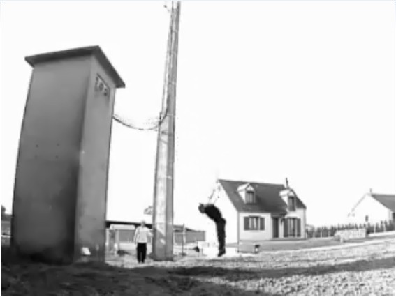
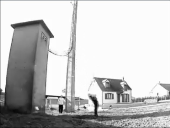
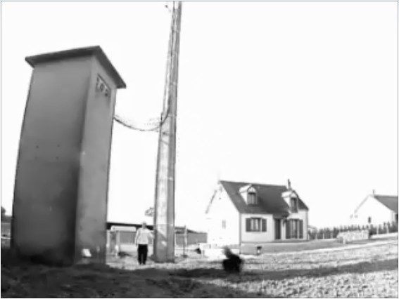
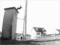
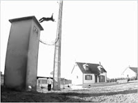
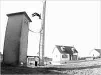
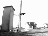
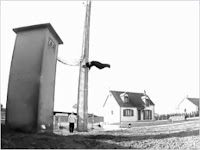
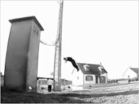
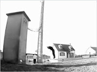
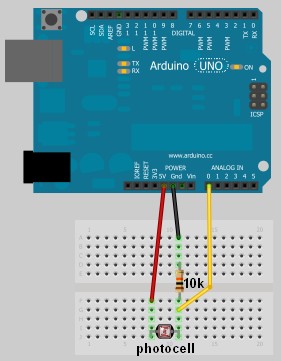
The photoresistor responds to changes in ambient light as my hand moves up and down. The Arduino sends the reading to a Processing sketch on the computer via a Serial command (through the USB cable). The processing sketch interprets the signal from the Arduino and selects the appropriate picture to display.
I took a series of screenshots from the following YouTube video: http://www.youtube.com/watch?v=h6nE8m74kDg And after borrowing a bit of code from these sites (1,2), the project was born.
This idea is not new, nor my own. There are many people who have done this project before, but I thought to blog about how I have done it, just for fun.

The code above was formatted using this site.
The code above was formatted using this site.


The photoresistor responds to changes in ambient light as my hand moves up and down. The Arduino sends the reading to a Processing sketch on the computer via a Serial command (through the USB cable). The processing sketch interprets the signal from the Arduino and selects the appropriate picture to display.
I took a series of screenshots from the following YouTube video: http://www.youtube.com/watch?v=h6nE8m74kDg And after borrowing a bit of code from these sites (1,2), the project was born.
This idea is not new, nor my own. There are many people who have done this project before, but I thought to blog about how I have done it, just for fun.
The Project Movie
Components Required
- Arduino Uno (and associated software), and USB cable
- Photoresistor or Photocell
- 10K resistor
- Wires to put it all together
- Processing IDE from http://processing.org
- Computer/laptop
The Arduino Sketch
The Arduino Code:
You can download the Arduino IDE from this site.1 | /* Jumper: Using an Arduino to animate: |
The code above was formatted using this site.
The Processing Code:
You can download the Processing IDE from this site.1 | /* Jumper: Using an Arduino to animate |
The code above was formatted using this site.
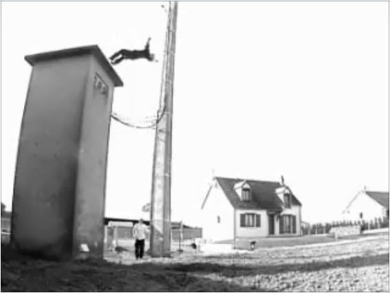
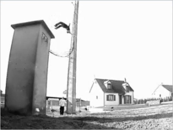
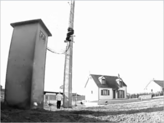
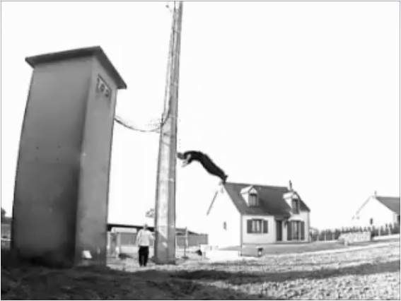
The pictures
Captured from this YouTube Video: http://www.youtube.com/watch?v=h6nE8m74kDg