I feel pretty good about today’s lecture, though things got a little rushed at the end.
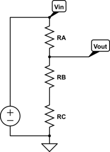
Three-resistor voltage divider for the first question.
I started with a “do now” question, similar to the one from Monday. Actually, I started with 2 questions. The first just asked what the output voltage would be for a 3-resistor voltage divider. The second repeated the question from Monday, but with the additional constraint that the power supply was 5 volts:
You have sensor whose resistance varies from 1kΩ to 4kΩ with the property it measures and a 5v power supply. Design a circuit whose output voltage varies from 1v (at 1kΩ) to 2v (at 4kΩ).
Several students realized that the first question was a hint for the second one and that the variable resistor had to be RB or RC, and could set up the equations and solve for RA and RC. This is a better performance than on Monday’s “do now”, but only about 1/3 of the class got it completely, and several of them were not confident of their results, so we again took time to go over the whole solution. I think that everyone (or almost everyone) understood the design process and how to set up and solve the equations by the end of the presentation, which I drew out of the students as much as possible. I also mentioned that we could have solved the problem with a different circuit (putting RC in parallel with RB instead of in series), but did not further elaborate on that point.
The do-now plus going over the solution took about 33 minutes, which is a little more time than I’d like to be spending on these questions. It would be good to get the time down to 15 minutes, but I don’t see how to do that without losing half the class. If the problems are easy enough that everyone gets them, then there is no point to taking up any class time with them, and if they are hard enough that 1/3 to 2/3 of the class don’t get them, then they need to be gone over in class.
After the do-now, we spent a little time discussing the “fit” command of gnuplot, since the students have to fit models to the data they collect tomorrow, and I’m not providing them a script this time (though they can modify the script that was provided in the first lab).
Finally, we got to the theoretical meat of the class—we discussed what sound was (ending up with variations in pressure for a fluid, though we discussed briefly transverse and shear waves in solids). Then I introduced microphones as transducers, trying to get the students to remember their elementary mechanics, so that we could do pressure→force→displacement→1/capacitance→voltage for electret mics. The hardest part was getting students to remember that a spring-mounted object had force proportional to displacement (a lot remembered the energy was somehow related to displacement squared and got stuck on that formula). I suspect that the local physics department would not be seeing a high score on the Force Concept Inventory for students coming out of their physics classes, as a lot of them seem to have concentrated on cramming formulas rather than learning fundamental concepts. Someone did remember Q=CV and someone else could reason from wanting voltage proportional to displacement to needing constant charge which let me introduce both conventional capacitance microphone (with a large resistor to voltage source) and electrets. I also explained that the electret had an enormous resistance, so we couldn’t get any measurable current out of it, and we needed an FET transistor to convert the voltage to a current.
Because both the do-now and extracting vague memories of physics from the students took longer than I had planned, we were a bit rushed for the last part of the lesson, which was a simple model of Ids vs Vds for the FET output stage of the electret mic. I asked for advice on drawing the plots for resistors and for current sources, and got the appropriate straight lines. I then drew a smooth transition between them and claimed that the simple FET models usually consisted of a linear region at low voltage (which my co-instructor refers to as the “triode” region, a usage I’ve seen in some other presentations) and a saturation region at high voltage, and that we usually try to stay out of the sublinear region in between.
I also said that the saturation region is not really constant, but has a slight upward slope, since they will be measuring the I-vs-V characteristic of the electret microphones tomorrow, and they will certainly be observing that. The lab handout gives them 4 models to fit: linear, constant current, an empirical blend of the two, and a model that allows current increase in the saturation region. Neither the 3rd nor the 4th model match the ones usually used in circuit simulators, but I had trouble fitting parameters to those models, even with voltage-modulated channel lengths, so I gave up and produced simple models with few parameters that can be fit pretty easily. We’ll be revisiting FETs again before the power-amp lab (where they’ll use pMOS and nMOS power FETs to make a class-D amplifier). Somewhere around then, I’ll have to give them some usable models for how saturation current varies with gate voltage, which I deliberately did not cover in this lecture.
I’m a bit worried about how big tomorrow’s lab is. There are again 2 parts:
- the DC characterization of the mic using the Arduino to gather data (plus a few hand-collected points for higher voltages than we can subject the Arduino to)
- designing a pull-up resistor to bias the mic into its normal operating range (in the saturation region) and observing the microphone output on the oscilloscope. I also asked students to hook up their loudspeakers to the signal generators, to provide known inputs to the mic, and some other little stuff, but I’ll probably be happy if everyone gets the first part done and manages to observe waveforms on the scope.
On Friday, most of the lecture will be standard EE stuff by my co-instructor (probably current sources, Thévenin equivalents, and Norton equivalents). I may have a do-now question at the beginning of the class, if I can come up with one that I think is pedagogically useful.
Filed under:
Circuits course Tagged:
Arduino,
circuits,
course design,
electret microphone,
teaching,
voltage divider