Posts with «arduino» label

Bluetooth Tutorial 1


Introduction:
The bluetooth shield used in this project is a great way to detach the Arduino from your computer. What is even better, is that the shield allows you to control your arduino from your mobile phone or other bluetooth enabled device through simple Serial commands. In this tutorial we will connect a Grove Chainable RGB LED to the bluetooth shield directly, and send simple commands using the Bluetooth SPP app on a Samsung Galaxy S2 to change the colour of the LED (Red , Green and Blue)


Parts Required:
Freetronics Eleven or any compatible Arduino.
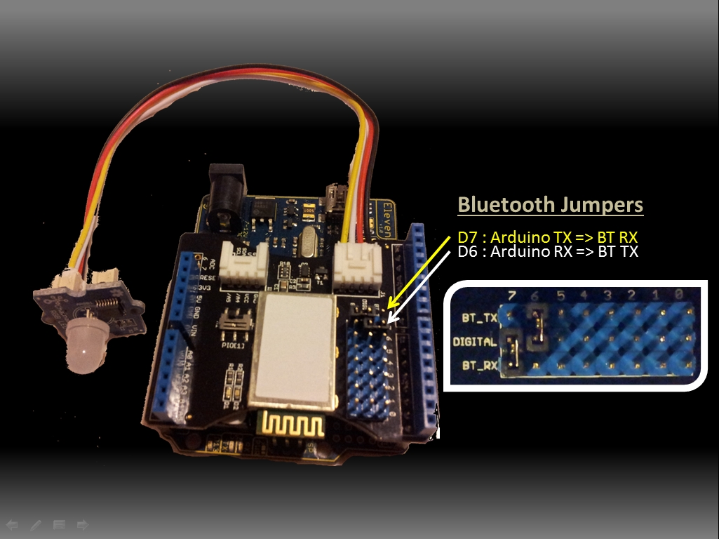
Bluetooth shield
Grove Chainable RGB LED
Grove Wire connectors


The Video:


The Arduino Sketch:


Arduino Code:
You can download the Arduino IDE from this site.


 1
2
3
4
5
6
7
8
9
10
11
12
13
14
15
16
17
18
19
20
21
22
23
24
25
26
27
28
29
30
31
32
33
34
35
36
37
38
39
40
41
42
43
44
45
46
47
48
49
50
51
52
53
54
55
56
57
58
59
60
61
62
63
64
65
66
67
68
69
70
71
72
73
74
75
76
77
78
79
80
81
82
83
84
85
86
87
88
89
90
91
92
93
94
95
96
97
98
99
100
101
102
103
104
105
106
107
108
109
110
111
112
113
114
115
116
117
118
119
120
121
122
123
124
125
126
127
128
129
130
131
132
133
134
135
136
137
138
139
140
141
142
143
144
145
146
147
148
149
150
151
152
153
154
155
156
157
158
159
/* This project combines the code from a few different sources.
This project was put together by ScottC on the 15/01/2013
http://arduinobasics.blogspot.com/

Bluetooth slave code by Steve Chang - downloaded from :
http://www.seeedstudio.com/wiki/index.php?title=Bluetooth_Shield

Grove Chainable RGB code can be found here :
http://www.seeedstudio.com/wiki/Grove_-_Chainable_RGB_LED#Introduction

*/

#include <SoftwareSerial.h> //Software Serial Port

#define uint8 unsigned char
#define uint16 unsigned int
#define uint32 unsigned long int

#define RxD 6 // This is the pin that the Bluetooth (BT_TX) will transmit to the Arduino (RxD)
#define TxD 7 // This is the pin that the Bluetooth (BT_RX) will receive from the Arduino (TxD)

#define DEBUG_ENABLED 1


int Clkpin = 9; //RGB LED Clock Pin (Digital 9)
int Datapin = 8; //RGB LED Data Pin (Digital 8)

SoftwareSerial blueToothSerial(RxD,TxD);

/*----------------------SETUP----------------------------*/
void setup() {
Serial.begin(9600); // Allow Serial communication via USB cable to computer (if required)
pinMode(RxD, INPUT); // Setup the Arduino to receive INPUT from the bluetooth shield on Digital Pin 6
pinMode(TxD, OUTPUT); // Setup the Arduino to send data (OUTPUT) to the bluetooth shield on Digital Pin 7
pinMode(13,OUTPUT); // Use onboard LED if required.
setupBlueToothConnection(); //Used to initialise the Bluetooth shield

pinMode(Datapin, OUTPUT); // Setup the RGB LED Data Pin
pinMode(Clkpin, OUTPUT); // Setup the RGB LED Clock pin

}

/*----------------------LOOP----------------------------*/
void loop() {
digitalWrite(13,LOW); //Turn off the onboard Arduino LED
char recvChar;
while(1){
if(blueToothSerial.available()){//check if there's any data sent from the remote bluetooth shield
recvChar = blueToothSerial.read();
Serial.print(recvChar); // Print the character received to the Serial Monitor (if required)

//If the character received = 'r' , then change the RGB led to display a RED colour
if(recvChar=='r'){
Send32Zero(); // begin
DataDealWithAndSend(255, 0, 0); // first node data
Send32Zero(); // send to update data
}

//If the character received = 'g' , then change the RGB led to display a GREEN colour
if(recvChar=='g'){
Send32Zero(); // begin
DataDealWithAndSend(0, 255, 0); // first node data
Send32Zero(); // send to update data
}

//If the character received = 'b' , then change the RGB led to display a BLUE colour
if(recvChar=='b'){
Send32Zero(); // begin
DataDealWithAndSend(0, 0, 255); // first node data
Send32Zero(); // send to update data
}
}

//You can use the following code to deal with any information coming from the Computer (serial monitor)
if(Serial.available()){
recvChar = Serial.read();

//This will send value obtained (recvChar) to the phone. The value will be displayed on the phone.
blueToothSerial.print(recvChar);
}
}
}


//The following code is necessary to setup the bluetooth shield ------copy and paste----------------
void setupBlueToothConnection()
{
blueToothSerial.begin(38400); //Set BluetoothBee BaudRate to default baud rate 38400
blueToothSerial.print("\r\n+STWMOD=0\r\n"); //set the bluetooth work in slave mode
blueToothSerial.print("\r\n+STNA=SeeedBTSlave\r\n"); //set the bluetooth name as "SeeedBTSlave"
blueToothSerial.print("\r\n+STOAUT=1\r\n"); // Permit Paired device to connect me
blueToothSerial.print("\r\n+STAUTO=0\r\n"); // Auto-connection should be forbidden here
delay(2000); // This delay is required.
blueToothSerial.print("\r\n+INQ=1\r\n"); //make the slave bluetooth inquirable
Serial.println("The slave bluetooth is inquirable!");
delay(2000); // This delay is required.
blueToothSerial.flush();
}


//The following code snippets are used update the colour of the RGB LED-----copy and paste------------
void ClkProduce(void){
digitalWrite(Clkpin, LOW);
delayMicroseconds(20);
digitalWrite(Clkpin, HIGH);
delayMicroseconds(20);
}

void Send32Zero(void){
unsigned char i;
for (i=0; i<32; i++){
digitalWrite(Datapin, LOW);
ClkProduce();
}
}

uint8 TakeAntiCode(uint8 dat){
uint8 tmp = 0;
if ((dat & 0x80) == 0){
tmp |= 0x02;
}

if ((dat & 0x40) == 0){
tmp |= 0x01;
}

return tmp;
}

// gray data
void DatSend(uint32 dx){
uint8 i;
for (i=0; i<32; i++){
if ((dx & 0x80000000) != 0){
digitalWrite(Datapin, HIGH);
} else {
digitalWrite(Datapin, LOW);
}

dx <<= 1;
ClkProduce();
}
}

// data processing
void DataDealWithAndSend(uint8 r, uint8 g, uint8 b){
uint32 dx = 0;

dx |= (uint32)0x03 << 30; // highest two bits 1,flag bits
dx |= (uint32)TakeAntiCode(b) << 28;
dx |= (uint32)TakeAntiCode(g) << 26;
dx |= (uint32)TakeAntiCode(r) << 24;

dx |= (uint32)b << 16;
dx |= (uint32)g << 8;
dx |= r;

DatSend(dx);
}

The code above was formatted using hilite.me

Notes:
You don't need to download a library to get this project running. But if you plan to use bluetooth shields to get 2 Arduinos to communicate to each other, then I would advise that you download the library files (which are just examples) from the Seeedstudio site : here.

Visit this site to setup your phone or laptop for bluetooth communication to the shield - here

The app used on my Samsung Galaxy S2 phone was "Bluetooth SPP"

You will initially need to enter a pin of '0000' to establish a connection to the Bluetooth shield - which will appear as "SeeedBTSlave" or whatever text you place on line 90 of the Arduino code above.


Warning !

Not all phones are compatible with the bluetooth shield.
If you have used this shield before - please let me know what phone you used - so that we can build a list and inform others whether their phone is likely to work with this project or not. Obviously - those phones that do not have bluetooth within - will not work :).
And I have not tried any other apps either

I got it to work very easily with my Samsung Galaxy S2 using the free Bluetooth SPP app from the google play store.

This was fun, but I want to make my own app !
Have a look at my latest 4-part tutorial which takes you step-by-step through the process of building your own app using the Processing/Android IDE.
You can build your own GUI interface on your Android Phone and get it to communicate via Bluetooth to your Arduino/Bluetooth Shield. Click on the links below for more information:


If you like this page, please do me a favour and show your appreciation :

 
Visit my ArduinoBasics Google + page.
Follow me on Twitter by looking for ScottC @ArduinoBasics.
Have a look at my videos on my YouTube channel.


However, if you do not have a google profile...
Feel free to share this page with your friends in any way you see fit.

Fourth day of circuits class

Today’s class went much better than last Friday’s.

I took the advice one of the students gave me last we and started with a “do now” question.  (She had actually suggested an “exit ticket”, but I don’t have the time management skills to leave a block of time at the end of class.)  The question I asked was a design task that was easy if you knew what you were doing, but subtly harder than the standard sort of text-book question, because it was a design question, not an analysis question:

You have sensor whose resistance varies from 1kΩ to 4kΩ with the property it measures.  Design a circuit whose output voltage varies from 1v (at 1kΩ) to 2v (at 4kΩ).

I gave the students 10 minutes to work on this at the beginning of class.  A good question to prompt discussion (according to the peer instruction blogs and websites) should be answerable by 30–80% of the students.  More than that and the question was too easy to be useful, and less than that and the question is too hard for peer discussion to be worthwhile.  It turned out that no one had gotten it after 10 minutes (too hard to use as a peer instruction question), so we used it as the basis for a class discussion.

Almost everyone realized that the desired circuit was a voltage source and a voltage divider (not too surprising, since that’s the only circuit they’ve used so far).  The majority also realized that the variable resistor had to be on the lower leg, between the output and ground, and a couple of the students could articulate why.  I suggested the common heuristic of trying extreme values (0 and ∞) for the variable resistor, to see whether the output voltage would go up or down as the resistance changed.

The students were then able to set up the simultaneous equations to solve for the input voltage and the fixed resistance.  The hole in everyone’s thinking when working on the problem initially is that they had not considered the voltage of the source as a design parameter to solve for, though one student had asked about it. This was the blind spot I was expecting, so I was able to use it as a teachable moment.  After we had the equations set up using mainly student input, I gave the students another minute or two to solve them, and about half the class was able to solve them correctly in the time provided. (I suspect that everyone could have if given enough time, but I didn’t want to take any more time in class—those who didn’t solve it in class could practice their algebra at home if they needed to.)  One student had made an algebra or arithmetic mistake, and gotten a source voltage smaller than one of the desired output voltages.  This was also a good mistake to get, since we could use it to talk about sanity checks on results.

I think that the 20 or so minutes of class was well spent, as we uncovered several important misconceptions, and raised awareness of all unspecified variables as potential design parameters, reasoning using extreme values, and the usefulness of sanity checks.

After that, we spent some time discussing different temperature sensors.  From the students, I got thermistor, infrared thermometer, mercury thermometer+camera, and enzyme + other sensor (pH, conductivity, color, …). I added RTD, silicon band-gap, and thermocouple to the mix.  We talked a little about the advantages and disadvantages of each. At the end, I also threw in bimetallic strips and tilt switches for one-bit digitization of temperature.  I wonder how many students will look at the thermostats in their apartments and try to figure out what sensor they include.

For the remainder of the class, we talked about gnuplot commands, particularly the “plot” command.

After class, several of us went over to the lab, where my son met us and helped the students install the DataLoger, python, pyserial, the Arduino environment, and gnuplot.  While he was doing that, I borrowed an Uno R3 Arduino board and made sure that all the computers in the labs had the drivers installed for it.  We had 2 installation failures: on one Windows laptop, my son was unable to get the serial ports to work and one Mac laptop couldn’t install gnuplot.

The problem with the gnuplot installation on that Mac was not solvable by the techniques in the comments for Installing gnuplot—a nightmare, because all the methods there assume that you can install the command-line tools “make” and “gcc”.  The Mac had 10.6.8 installed, but the student had never bothered to install the development tools and had lost the original CD-ROM with the Xcode tools on it.  The Apple Developer site does not provide the command-line tools for anything older than 10.7.3.  The only workaround we could find was to download the 4.1GByte complete Xcode suite for OS 10.6.8, which I was not willing to wait around for. (Other students with 10.6.8 had no trouble installing gnuplot, because they already had the command-line tools, though they’d never used them.)

I did not look at the problem on the Windows machine (the student had to leave for class before I became available), but I don’t know that I could have done anything—my son knows more about Windows than I do, so if he was stuck, I probably would have been also.

Next year I’m going to want to do an install session before the first lab.  (Or, if we go to 2 labs a week, as the first lab.)

On Wednesday, I’ll start with another “do now” question, though I’m not sure what it’ll be on, since I’ve not yet gotten to the material for this week’s lab: how a microphone works. I’ll do a tiny bit of gnuplot (just the “fit” command) and try to get through how a microphone works and an idealized i-vs-v plot for the FET output of the microphone.


Filed under: Circuits course Tagged: Arduino, circuits, gnuplot, parts, teaching, temperature measurement, voltage divider

Arduino Esplora Video Game

It’s the project the Arduino Esplora seemingly was designed to create: a handheld video game. Mike Barela added a 1.8″ display from Adafruit, and adapted the code created by another maker named R0D0T. I was looking for a game that was more than the basics to show off the Esplora [...]

Read the full article on MAKE

Rover 5 Motor Issue ?

Hello all

This is my first post in this forum and I hope you can help me. I just got a Rover 5 ( the 4 wheel edition) and the Dagu 4 channel motor controller.

Everything is connected with my Arduino Mega and I have no problems to control the motors and read the current amp value from the motors. I noticed that the motors are consuming up to 1.6 A and I think this is too much ? The Rover was not touching the ground and the default chain was mounted on the tire ?

Should I try to make the chains more loose ?

read more

Let's Make Robots 14 Jan 12:48

Arduino Uno + Dagu 4 channel motor controller - power issues?

I have an Uno controlling a 4 channel Dagu motor controller with encoder support. Got this a month ago. (It's the red PCB version).

Although it works, I have read that I shall not power the motors before powering the control logic.

But does that really mean that if the controller voltage dies out in the field, and there's still juice in the motor batteries, the Dagu controller will burn ?

I saw OddBot said this might be the case, at least if you powered it up in the wrong order.

read more

Let's Make Robots 13 Jan 12:19

Atmel RF ATmegas

Hi.

Has anyone attempted using these? I was wondering how hard it would be to use them with the arduino bootloader for my as-yet-not-started RC system project (I will get round to it soon, hopefully). The Zigduino seems to use them, and they've supplied a library to operate the in-built radio. I'm just wondering whether I'd have to be careful with PCB layout etc. to avoid interference.

read more

Let's Make Robots 12 Jan 14:49

Control a Virtual World Using Music

Arboration controls a projected landscape based on the musical input of the user.

Read the full article on MAKE

MAKE » Arduino 11 Jan 20:00
ableton  arduino  capacitive  itp  max  msp  music  projection  unity3d  

Printing images with a wood burning CNC machine

Just to clear up any confusion from the title, this wood burning CNC machine runs on electricity. The wood burner acts as the print head. It’s the thing in the upper right of the field that looks a bit like a soldering iron. In this case it’s being used like a dot matrix printer.

We suppose this is a form of halftone printing, although it doesn’t produce the uniformity we’ve seen with mill-based halftone techniques. [Random Sample] built the machine from wood, drawer sliders, and stepper motors with toothed belts. His Python script takes an image and transforms it into a file which can be used to guide each of the three axes of the machine. An Arduino receives these commands via the USB connection. Each image prints in a grid, with darker pixels created by leaving the hot tip in contact with the wood for a longer period of time.

Don’t miss the sample video embedded after the jump.

[Thanks Ian via Reddit]


Filed under: cnc hacks
Hack a Day 11 Jan 16:59

10 seconds count down using Arduino

This is one of my 1st Arduino projects. Along with Arduino, I've used a seven segmeent led display and a piezzo buzzer. First, it beeps to indicate start. Then, counts down from 9 to 0, beeps three times. Finally, it beeps for the last time but this time the beep lasts longer.