Posts with «arduino» label

beginer in electronics needs to program

hi, im a twelve year old boy who is not an expert  AT ALL, but knows the basics

i've made bristlebots, speaker tones, dc motor cars  and other stuff

BUT

when i have to program  in arduino UNO i just copy other codes from other people

cause...  I dont know how to program at all!!!! i think arduino's language is c,and i don't know  how to program


anybody knows how to program arduino

and can give me a little tutorial about key words and etcetera like setup, delay, control of dc motors sensor etc...

read more

Weather station graphs history on webpage

Kudos go out to [Jose] for his work getting so many different components to talk to each other in this Arduino weather station that using a Raspberry Pi to display the data online.

The components shown above make up the sensor package. There’s an Arduino with a custom shield that interfaces the barometric pressure sensor, real-time clock chip, a digital temperature sensor, and a humidity sensor. On top of that shield is an XBee shield that lets this push data back to the base station. [Jose] also rolled in an LCD character display and a few buttons so that the user may view weather data without heading to the web.

A Raspberry Pi board makes up the other half of the XBee pair. It harvests the incoming data from the radio module using a USB to Serial converter cable. You can see the data log on the webpage linked above. Just choose the “LIVE” menu option and click on “Daily” to get a better overview of humidity and pressure changes.


Filed under: home hacks

Open Hardware Pinoccio Is A Wireless, Web-Ready Microcontroller

I met Eric Jennings at the Hardware Innovation Workshop last May where he was showing off plans for a new wireless Arduino-compatible mircocontroller board. After going through nine prototypes since then, he and co-founder Sally Carson launched the Pinoccio this week. Here’s how Eric describes the platform: Pinoccio is a [...]

Read the full article on MAKE

Sonar Project Tutorial


Introduction:
This project utilises the HC-SR04 ultrasonic sensor to scan for nearby objects. You can program the Arduino to sound an alarm when the sensor detects an object within a specific vicinity. Connecting it to a computer allows data to be plotted to make a simple sonar scanner. The scanning ability is made possible through the use of a hobby servo motor SG-5010, and an Adafruit motor shield v1.0.
This project could easily be extended to provide object avoidance for any robotics project. This tutorial was designed so that you could see how the components interact, and also to see how you can use and expand the functionality of the motor shield.


Parts Required:
Freetronics Eleven or any compatible Arduino.
Adafruit motor shield v1.0
HC-SR04 Ultrasonic Sensor
MG-995  or SG-5010 Standard servo
Mini Breadboard 4.5cm x 3.5cm
Female header pins to allow easy access to the analog pins on the Motor Shield
Piezo buzzer - to sound alarm
9V Battery and Battery Clip
Wiresto connect it all together

Gauge parts:

Paper (to print the face of the gauge), and some glue to stick it to the wood.
MDF Standard panel (3mm width) - for the top and base of the gauge, and the pointer.
Galvanized bracket (25x25x40mm)
Timber screws: Hinge-long threads csk head Phillips drive (4G x 12mm)
Velcro dots - to allow temporary application of the mini-breadboard to the gauge.

The gauge was used as a customisable housing for the Arduino and related parts, and to provide some visual feedback of the servo position.


The Video:


The Arduino Sketch:


 Part of the sketch above was created using Fritzing.

The Servo motor can be connected to either of the Servo motor pins (Digital 9 or 10). In this case, the Servo is attached to digital pin 10.Make sure you read the servo motor data sheet and identify the VCC (5V), GND, and Signal connectors. Not all servos have the same colour wires. My servo motor has a white signal wire, a red VCC wire and a black GND wire.

Also when connecting your wires to the HC-SR04, pay attention to the front of the sensor. It will identify the pins for you. Make sure you have the sensor facing the correct way. In this sketch, the sensor is actually facing towards you.

In this sketch - we connect the
    Echo pin to Analog pin 0 (A0).
    Trigger pin to Analog pin 1 (A1)
    VCC to a 5V line/pin 
    and GND to a GND line/pin

Pay attention to your motor shield, I have seen some pictures on the internet where the 5V and GND are reversed.


Arduino Code:
You can download the Arduino IDE from this site.

The motor shield requires the Adafruit motor shield driver library to be installed into the Arduino IDE.

 1
2
3
4
5
6
7
8
9
10
11
12
13
14
15
16
17
18
19
20
21
22
23
24
25
26
27
28
29
30
31
32
33
34
35
36
37
38
39
40
41
42
43
44
45
46
47
48
49
50
51
52
53
54
55
56
57
58
59
60
61
62
63
64
65
66
67
68
69
70
71
72
73
74
75
76
77
78
79
80
81
82
83
84
85
86
87
88
89
90
91
92
93
94
95
96
97
98
99
100
101
102
103
104
/* ArduinoBasics: Sonar Project - Created by Scott C on 10 Jan 2013
http://arduinobasics.blogspot.com/2013/01/arduino-basics-sonar-project-tutorial.html

This project uses the Adafruit Motor shield library (copyright Adafruit Industries LLC, 2009
this code is public domain, enjoy!)

The HC-SR04 sensor uses some code from the following sources:
From Virtualmix: http://goo.gl/kJ8Gl
Modified by Winkle ink here: http://winkleink.blogspot.com.au/2012/05/arduino-hc-sr04-ultrasonic-distance.html
And modified further by ScottC here: http://arduinobasics.blogspot.com/
on 10 Nov 2012.
*/

#include <AFMotor.h>
#include <Servo.h>

// DC hobby servo
Servo servo1;

/* The servo minimum and maximum angle rotation */
static const int minAngle = 0;
static const int maxAngle = 176;
int servoAngle;
int servoPos;
int servoPin = 10;


/* Define pins for HC-SR04 ultrasonic sensor */
#define echoPin A0 // Echo Pin = Analog Pin 0
#define trigPin A1 // Trigger Pin = Analog Pin 1
#define LEDPin 13 // Onboard LED
long duration; // Duration used to calculate distance
long HR_dist=0; // Calculated Distance
int HR_angle=0; // The angle in which the servo/sensor is pointing
int HR_dir=1; // Used to change the direction of the servo/sensor
int minimumRange=5; //Minimum Sonar range
int maximumRange=200; //Maximum Sonar Range

/*--------------------SETUP()------------------------*/
void setup() {
//Begin Serial communication using a 9600 baud rate
Serial.begin (9600);

// Tell the arduino that the servo is attached to Digital pin 10.
servo1.attach(servoPin);

//Setup the trigger and Echo pins of the HC-SR04 sensor
pinMode(trigPin, OUTPUT);
pinMode(echoPin, INPUT);
pinMode(LEDPin, OUTPUT); // Use LED indicator (if required)
}

/*----------------------LOOP()--------------------------*/
void loop() {

/* check if data has been sent from the computer: */
if (Serial.available()) {

/* This expects an integer from the Serial buffer */
HR_angle = Serial.parseInt();

/* If the angle provided is 0 or greater, then move servo to that
position/angle and then get a reading from the ultrasonic sensor */
if(HR_angle>-1){
/*Make sure that the angle provided does not go beyond the capabilities
of the Servo. This can also be used to calibrate the servo angle */
servoPos = constrain(map(HR_angle, 0,180,minAngle,maxAngle),minAngle,maxAngle);
servo1.write(servoPos);

/* Call the getDistance function to take a reading from the Ultrasonic sensor */
getDistance();
}
}
}

/*--------------------getDistance() FUNCTION ---------------*/
void getDistance(){

/* The following trigPin/echoPin cycle is used to determine the
distance of the nearest object by bouncing soundwaves off of it. */
digitalWrite(trigPin, LOW);
delayMicroseconds(2);

digitalWrite(trigPin, HIGH);
delayMicroseconds(10);

digitalWrite(trigPin, LOW);
duration = pulseIn(echoPin, HIGH);

//Calculate the distance (in cm) based on the speed of sound.
HR_dist = duration/58.2;

/*Send the reading from the ultrasonic sensor to the computer */
if (HR_dist >= maximumRange || HR_dist <= minimumRange){
/* Send a 0 to computer and Turn LED ON to indicate "out of range" */
Serial.println("0");
digitalWrite(LEDPin, HIGH);
} else {
/* Send the distance to the computer using Serial protocol, and
turn LED OFF to indicate successful reading. */
Serial.println(HR_dist);
digitalWrite(LEDPin, LOW);
}
}

The code above was formatted using hilite.me

Notes:
Servo Angles: You will notice on line 22, the maximum servo angle used was 176. This value was obtained through trial and error (see below).

Calibrating the servo angles
You may need to calibrate your servo in order to move through an angle of 0 to 180 degrees without straining the motor. Go to line 21-22 and change the minAngle to 0 and the maxAngle to 180. Once you load the sketch to the Arduino/Freetronics ELEVEN, you can then open the Serial Monitor and type a value like 10 <enter>, and then keep reducing it until you get to 0. If you hear the servo motor straining, then move it back up to a safe value and change the minimum servo angle to that value. Do the same for the maximum value.

In this example, the servo's minAngle value was 0, and maxAngle value was 176 after calibration, however, as you can see from the video, the physical range of the servo turned out to be 0 to 180 degrees.


The Processing Sketch

You can download the Processing IDE from this site.

 1
2
3
4
5
6
7
8
9
10
11
12
13
14
15
16
17
18
19
20
21
22
23
24
25
26
27
28
29
30
31
32
33
34
35
36
37
38
39
40
41
42
43
44
45
46
47
48
49
50
51
52
53
54
55
56
57
58
59
60
61
62
63
64
65
66
67
68
69
70
71
72
73
74
75
76
77
78
79
80
81
82
83
84
85
86
87
88
89
90
91
92
93
94
95
96
97
98
99
100
101
102
103
104
105
106
107
108
109
110
/* Created by ScottC on 10 Jan 2013 
http://arduinobasics.blogspot.com/2013/01/arduino-basics-sonar-project-tutorial.html
*/

import processing.serial.*;

int distance;
int angle=0;
int direction=1;

int[] alphaVal = new int[100]; // used to fade the lines
int[] distance2 = new int[100]; // used to store the line lengths
int lineSize = 4; // line length multiplier (makes it longer)

String comPortString;
Serial comPort;

/*---------------------SETUP---------------------------*/
void setup( ) {
size(displayWidth,displayHeight); //allows fullscreen view
smooth();
background(0); // set the background to black

/*Open the serial port for communication with the Arduino
Make sure the COM port is correct - I am using COM port 8 */
comPort = new Serial(this, "COM8", 9600);
comPort.bufferUntil('\n'); // Trigger a SerialEvent on new line

/*Initialise the line alphaValues to 0 (ie not visible) */
for(int i=0; i<91; i++){
alphaVal[i] = 0;
}
}

/*---------------------DRAW-----------------*/
void draw( ) {
background(0); //clear the screen

/*Draw each line and dot */
for(int i=0; i<91; i++){

/*Gradually fade each line */
alphaVal[i]=alphaVal[i]-4;

/*Once it gets to 0, keep it there */
if(alphaVal[i]<0){
alphaVal[i]=0;
}

/*The colour of the line will change depending on the distance */
stroke(255,distance2[i],0,alphaVal[i]);

/* Use a line thickness of 2 (strokeweight) to draw the line that fans
out from the bottom center of the screen. */
strokeWeight(2);
line(width/2, height, (width/2)-cos(radians(i*2))*(distance2[i]*lineSize), height-sin(radians(i*2))*(distance2[i]*lineSize));

/* Draw the white dot at the end of the line which does not fade */
stroke(255);
strokeWeight(1);
ellipse((width/2)-cos(radians(i*2))*(distance2[i]*lineSize), height-sin(radians(i*2))*(distance2[i]*lineSize),5,5);
}
}

/* A mouse press starts the scan. There is no stop button */
void mousePressed(){
sendAngle();
}

/*When the computer receives a value from the Arduino, it will update the line positions */
void serialEvent(Serial cPort){
comPortString = cPort.readStringUntil('\n');
if(comPortString != null) {
comPortString=trim(comPortString);

/* Use the distance received by the Arduino to modify the lines */
distance = int(map(Integer.parseInt(comPortString),1,200,1,height));
drawSonar(angle,distance);

/* Send the next angle to be measured by the Arduino */
sendAngle();
}
}

/*---------------------------sendAngle() FUNCTION----------------*/
void sendAngle(){
//Send the angle to the Arduino. The fullstop at the end is necessary.
comPort.write(angle+".");

/*Increment the angle for the next time round. Making sure that the angle sent
does not exceed the servo limits. The "direction" variable allows the servo
to have a sweeping action.*/
angle=angle+(2*direction);
if(angle>178||angle<1){
direction=direction*-1;
}
}

/*-----------------sketchFullScreen(): Allows for FullScreen view------*/
boolean sketchFullScreen() {
return true;
}

/*----------------- drawSonar(): update the line/dot positions---------*/
void drawSonar(int sonAngle, int newDist){
alphaVal[sonAngle/2] = 180;
distance2[sonAngle/2] = newDist;
}


The Processing Output


The PICnDuino Review

For those of you that can’t make a decision between buying an Arduino and a PIC processor, [Brad] has come up with a novel solution, the PICnDuino. We’ve featured him before with his [Retroball] project, but this time Brad has been full funded on Kickstarter, and is pre-selling boards for delivery in March.

[HAD], specifically I, was fortunate enough to be sent one of the boards to try out early. I’ve worked with an Arduino before, but never a PIC processor, so read on to see if it was actually as easy as the tutorial video (at the end of the article) would have you believe it is to get started.

I was sent both a black board fully populated, as well as several blanks in the various colors pictured below.  After loosely attaching the headers, I found that the oscillator on the bottom makes the board sit up a bit when placed into a breadboard. This is actually a clever design feature to make sit up a bit to allow USB attachment while breadboarded. After a quick physical inspection, the real trick would be seeing if it worked as advertised.

The first challenge for me was that, according to the documentation, this board runs in Windows or a virtualisation environment. I normally run Ubuntu, so, grabbing my wife’s circa 2000 vintage XP notebook, I downloaded and Amicus and Arduino software as explained in the video tutorial. The tutorial really spells out how to get the software running. This would be great for a total beginner, and made it so I didn’t have to even poke around for where to get the software.

The only issue I had connecting to the board(s?)was that I had to manually install the Amicus18 USB driver. I’m a total noob when it comes to the PIC processor, and only have limited experience with the Arduino, but once the driver was updated, it was quite easy to get everything going.

After programming a “blink” sketch using it as an Arduino, I then flipped a switch and opened the Amicus IDE. Programming the PIC was also simple, although I had to use a and modify a program called “LED_Flash” to match the video instead of the “blink” program as described in the tutorial. It was a bit strange to see the built in blinking light for the Arduino still working while the PIC was being programmed, as well as both built-in lights blinking slightly offset while running simultaneously.

The documentation is extremely well done for a product that won’t even be available for delivery until March 2013. I’m really excited to play with it more, and I think it will be a great tool for people to either run two processors simultaneously, or just have the option of learning to program both a PIC and (n) Arduino. So check it out here, and get it shipped worldwide straight out of Australia!

Side note, bonus points if you can tell from the two pictures what kind of computer I used for this review!


Filed under: arduino hacks, reviews

Audio VU Meter.

Simple project, some kind of “Arduino-Wiki” for beginners.

How to do measurements right:

  1. Biasing AC input using resistor divider and scaling up / down if necessary;
  2. Sampling fast and accurately using direct access to Control Registers of ADC and Timer1;
  3. Subtract whatever was added at step #1 from result of Analog / Digital conversion and Square;
  4. Average / accumulate, filtering following VU specification;
  5. Sqrt – take square root, Log10 – transform to dB scale;
  6. Display.

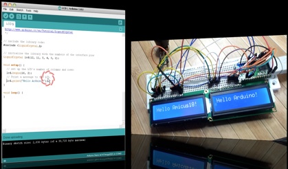
 1.   Hope, you follow my advice and hack your cheap USB speakers, to get nice ( pre-assembled ! ) analog “front-end” for this project. If not, than get your soldering iron to work, minimum two resistors and 1 cap would required, assuming you already have display wired up and running.

 First things with AC measurements ( audio in this category ) on Atmel microcontroler is to get rid of negative half-wave of the input signal, and this what front-end circuitry should do. There are at least two option: rectifying AC to DC before voltage could reach arduino analog input, or biasing signal with external DC offset. Rectification, could nicely be done with help of specifically design IC, LM3914 / 15 / 16 for example. But in this article, I’d describe second alternative, as it’d be not fare to ask you to hack your speakers and than tell you to solder another board…. Here is my set-up, slightly modified version from last blog:

When AC input signal is mixed with DC offset, so it stays always in positive area, ( think about sine, which defined betseen -1 and +1, if I add +1 it always would be positive ), I only save arduino life, preventing it from destruction by negative voltage. When arduino ADC completes conversion from analog to digital form, I don’t need DC offset anymore, and it should be subtracted.

  NOTE: DC voltage was added just to pass audio through arduino ADC. 

2. Sampling subroutine is running at 40 kHz, that is more than enough for ANY application. You may decrease sampling rate to lower CPU load, with current settings VU metering consumes more than 50%. Higher sampling rate gives better linearity / precision over wide band, the same time with regular audio content even 10 kHz sampling would provide better than 1 dB accuracy. All input capture process goes in Interruption subroutine, which is configured in setup. Two channels of Timer 1 Configured to run in parallel, “A” is responsible to keep clock at 40 kHz sharp, and “B” fires start conversion event to ADC with the same speed. Restarting new conversion via hardware provides lowest phase noise compare to any other way of doing this.

     ADCSRB = ((1<<ADTS2)| // Sets Auto Trigger source – Timer/Counter1 Compare Match B
                       (0<<ADTS1)|
                       (1<<ADTS0));

/* Set up TIMER 1 – ADC sampler */
       TCCR1A = ((1<<WGM11) | (1<<WGM10)); // Mode 15, Fast PWM
       TCCR1B = ((1<<WGM13) | (1<<WGM12)); // Mode 15, Fast PWM

       TCCR1B |= (1<<CS10); // clk/1 prescaling.
       OCR1A = SMP_TMR1;
       OCR1B = SMP_TMR1;

      TIFR1 |= (1<<OCF1B); 
      TIMSK1 |= (1<<OCIE1B);

3 .  As you can see in a code snipped below, adc_Offst is subtracted from new ADC result. Quite simple, value of DC offset ( adc_Offst ) was obtained in setup() during start up, using Arduino IDE “analogRead”. The only problem with this simple solution, is that no audio should be present at this moment ( start up ) at input, otherwise all measurements would be erroneous.

 ISR(TIMER1_COMPB_vect)
   {  
      int32_t temp = ADC – adc_Offst; 
                 temp = temp * temp;
      if ( temp > ppm_Level ) ppm_Level = ((ppm_Level * 255) + temp) >> 8;
      else ppm_Level = (ppm_Level * 16383) >> 14; 
   }  

4. The same piece of code includes VU filtering algorithm. I was trying to get as close to standard as possible, but tough timing requirements ( 25 usec ! ) doesn’t allow get full satisfaction. Attack time is very close to specification, 3 milliseconds or so. Decay, I’d estimate in 200 milliseconds, which is less than recommended 650 milliseconds for Peak Program Meter (PPM), and also less than 300 milliseconds for regular VU.  The limits come from 32-bit integer math, from one side, and high sampling rate from another.

updated:

This comparison operator     if ( temp > ppm_Level )  separates attack – when new value is bigger than stored, and decay – when new value is smaller. Now, lets me explain what this line of code does:

     ppm_Level = ((ppm_Level * 255) + temp) >> 8;
Rewriting it to:  ppm_Level = ((ppm_Level * 255) + temp) / 256;

and than:          ppm_Level = ppm_Level *  ( 255 / 256 ) + temp * ( 1 / 256 );

reveals:            ppm_Level = ppm_Level *  0.99609375 + temp * 0.00390625;

Which is simple, single pole Low Pass Filter. For more details on recursive filtering I’d refer to this book. Equation 19.2.   Trick with right shift operator (>>8) is just to improve speed of calculation. Remind you, that Arduino doesn’t have floating point CPU, and any mathematics work with floating point coefficient very slow.

Same with filtering decay process, the difference is only in coefficient value.

( >> 14) is the same as 1 / 16384,   and so   16383 / 16384 = 0.999938965.

5.   Read comments, please:

    int32_t temp;

     temp = ppm_Level;                        // Take a copy, so Real Value not affected by calculation.
     temp = sqrt(temp);

    rms_Level = 20.0 * log10(temp +1); // Calculated, available over Serial

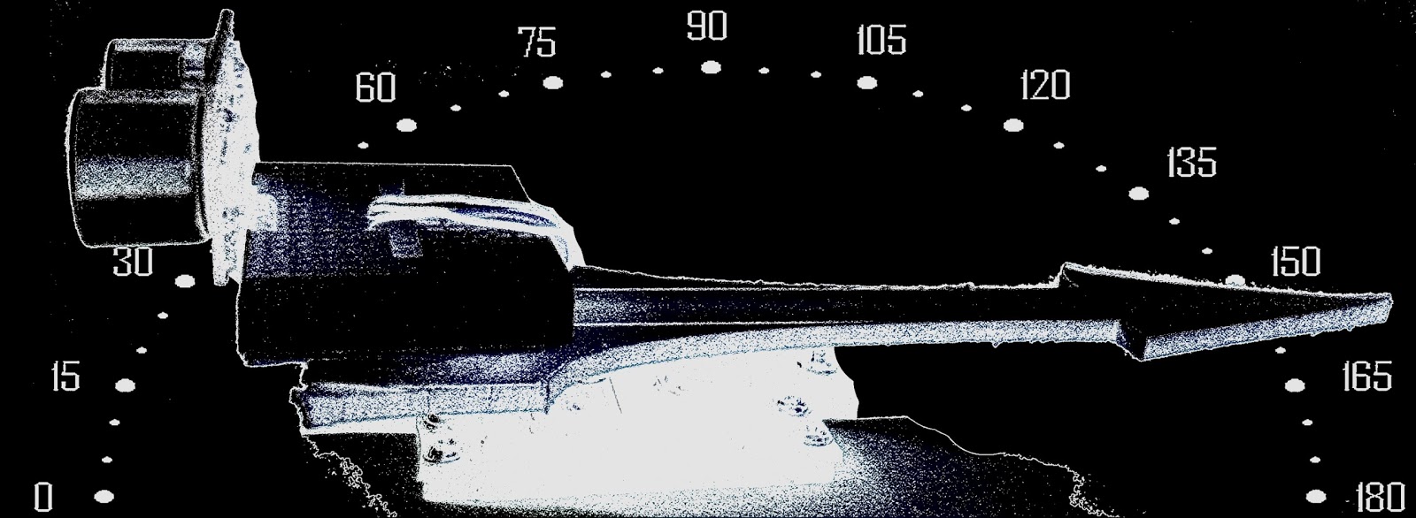
6. Last part, drawing VU indicator on graphical display. Ones again, referring you to short hardware description of using model.  There is not much to say, all display interface based on GLCD library. The only “tweak” from my side, is that I added “if” condition in front of drawing needle subfunctions:

      if ( abs(st1 – st2) > 3 )                          //  ~1/3 dB

I discovered, that DrawLine is quite slow, 4 calls ( 2 – erase, 2 – draw, all double – to make needle thicker ) take 125 milliseconds, so it make sense not to draw anything if there is not big difference between old and new needle position. At least, new position has to be off by width of the needle itself.

Link to Arduino (UNO) sketch: download.


Amanda Ghassaei’s Glitchbox

Amanda Ghassaei built this fun Arduino-powered noisemaker: The glitchbox is a sample-based drum machine used for live audio or MIDI sequencing. The buttons on the front of the instrument play back nine audio samples stored in its memory. A switch on top records and loops sequences of these samples. Once [...]

Read the full article on MAKE

MAKE » Arduino 09 Jan 15:00

Faulty board?


Hello

I bought a card "Dual 15A Wild Thumper Arduino DC Motor Controller"

When I connect the battery (voltage OK) to the card the led "good battery" lights for a while and then goes off.

The "power" led is ON, the 5V output is ok, the corrent is about 40mA.

The board doesnt work.

Do I had to send the card to the seller or can I do  other controls.?

Thanks, Stefano

PS Sorry for my bad english language


A blinky fedora to ring in the New Year

[Garrett Mace] decided to dress festive for New Year’s Eve. What he came up with is a fedora ringed in LEDs that react to music. The hardware uses 5050 LEDs on strips. Three of them encircle the head-gear providing a total of 114 RGB pixels. Each is a WS2811 module — a part which we’re seeing more and more of lately.

The video clip after the break starts off with a few minutes of demonstration. [Garrett] managed to code all kinds of animations for the hardware including several different styles of color sweeps and fades. You may start to think that the three bands always display the same patterns but keep watching and you’ll see a sparkle pattern that proves each dot can be addressed individually.

About 2:20 seconds into the video [Garrett] explains how he pulled it off and shows off the driver hardware. The strips are glued to a band of webbing that slides over the hat. The wires that drive the lights were fed through the center of some paracord and connect to an Arduino housed in a 3D printed case. Power is provided by a portable USB battery with a ShiftBrite shield and an MSGEQ7 chip complete the parts list.

[via Reddit]


Filed under: led hacks, wearable hacks
Hack a Day 08 Jan 17:01

Arduino based Cybot

Primary image

What does it do?

Navigate around via ultrasound but will eventually do more

I recently recieved lots of Cybot parts from my friend who collected the parts of eBay, no longer wanting them he kindly gave them to me, my plan was to convert it to an Arduino based robot.

If you are not aware what a Cybot looks like here is a picture I took before the dismantling process:

The Cybot had some good features; line following, IR remote control, speech recognition and even the ability to find its IR ball and shoot goals into an IR goal.

Cost to build

Embedded video

Finished project

Number

Time to build

12 hours

Type

wheels

URL to more information

Weight

read more