Posts with «arduino» label

Two new little tools for your tinkering time with Arduino

Two new Arduino products are available starting today from the Arduino Store. Read below for details!

Arduino USB Host Shield

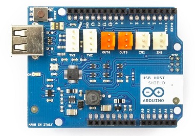
This shield allows you to connect devices to your Arduino using a USB port, for example game controllers, digital cameras, phones, keyboards, etc:

- it is based on the MAX3421E, which is a USB peripheral/host controller containing the digital logic and analog circuitry necessary to implement a full-speed USB peripheral or a full-/low-speed host compliant to USB specification rev 2.0.

- it can be used with the “USB Host Library for Arduino” hosted by Lauzus from circuits@home on GitHub (click to download zip).

If you want to see how to use it, take a look at this tutorial from Officine Arduino which used it to add wireless to an RC Car.

Buy USB Host Shield now


——————————-

ArduinoISP

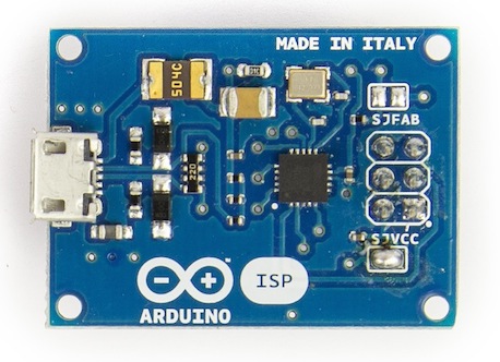
It’s a tiny AVR-ISP (in-system programmer) based on David Mellis’ project FabISP and useful to anyone needing more space on the Arduino board. Uploading a sketch with an external programmer can be used for three main reasons:

- remove the bootloader and use the extra space for your sketch

- burn the bootloader on your Arduino, so you can recover it if you accidentally corrupt the bootloader.

- when you use a new ATmega microcontroller in your Arduino, and you need the bootloader in order to upload a sketch in the usual way.

For more details about using the Arduino ISP please visit the Getting Started page

Learn how to program an ATtiny and to read your Arduino built-in EEPROM using ArduinoISP in the tutorials on Scuola.

Buy Arduino ISP now


Internet of things with Arduino Yún and Yaler

Explore this tutorial  demonstrating how the Arduino Yún can be controlled from anywhere with any internet connected web browser. The solution is provided by Bo Peterson using the Yaler service which means that the Yún can be reached from any network without knowing the IP-address, and without any port forwarding on the router where the Yún is connected.

A common problem in home automation and internet of things applications is that it is difficult to reach devices connected behind wifi routers from the outside. There are different approaches to overcome this problem:

  • Port forwarding and static ip addresses. This solution requires the user of the connected device to know how to configure a router and have access to router administration which is not always possible. A Yun tutorial with port forwarding is found here.
  • Polling is a technique where the connected device at regular intervals checks with an external server if the device should take action. This solution requires no configuration of the router but it creates extra network traffic and response delays.
  • A third way is to use WebSockets which is a way of providing real time full-duplex communication over TCP. Spacebrew is a good open source toolkit for connected devices using WebSockets. Autobahn is another infrastructure that can be used.
  • Reverse HTTP is the solution that will be used in this tutorial. We will use Yaler which is an open source relay infrastructure that gives access to connected devices with very little configuration.

Follow the tutorial and get the code at this link.

Arduino Blog 28 Jun 19:06
arduino  arduino yún  iot  yaler  yún  

Build a Bass Master 3000 Carnival Game

We’ve all been there. You are having fun walking around the carnival when you suddenly find yourself walking past the carnival games. The people working the booths are taunting you, trying to get you to play their games. You know the truth, though. Those games are rigged. You don’t know how they do it. You just know that they do… somehow.

Now you can put your worries to rest and build your own carnival game! [John] built his own “Bass Master 3000” style carnival game and posted an Instructable so you can make one too.

The game is pretty straightforward. You have a giant fish-shaped target with a wide open mouth. You take hold of a small fishing reel with a rubber ball on the end. Your goal is to cast the ball out and hit the fish in its big mouth. If you hit the mouth, you get to hear a loud buzzer and see some flashing lights. The system also uses a webcam to take a candid photo of the winner. A computer screen shows all of the winners of the day.

The brain of the system is an Arduino Yún. The Yún is similar to an Uno but it also has some extra features. Some good examples are an Ethernet port, a wireless adapter, and an SD card slot. The mouth sensors are just two piezo elements. Each sensor is hooked up to the Arduino through a small trim pot. This allows you to dial in the sensitivity of each sensor. The lights and the buzzer are controlled via a relay, triggered by a 5V digital pin on the Arduino.

The Yún actually has a small on-board Linux computer that you can communicate with from inside the Arduino environment. This allows [John] to use the Yún to actually take photos directly from a web cam, store them on the local SD card, and display them on a local web server. The web server runs a simple script that displays a slide show of all of the photos stored on the card.

The final piece of the game is the physical target itself. The target is painted using acrylic paint onto a small tarp. The tarp is then attached to a square frame made from PVC pipe. The mouth of the fish is cut out of the tarp. A large piece of felt is then placed behind the hole with the piezo sensors attached. A short length of copper pipe helps to weigh down the bottom of the felt and keep it in place. The important thing is to make sure the felt isn’t touching the tarp. If it touches, it might be overly sensitive and trigger even when a player misses.

Now you know how to build your own Bass Master 3000 carnival game. Whether you rig the game or not is up to you. Also, be sure to check out a video of the system working below.


Filed under: Arduino Hacks
Hack a Day 28 Jun 12:00

Generate Clocks with the SI5351 and an Arduino

If you’re dealing with RF, you’ll probably have the need to generate a variety of clock signals. Fortunately, [Jason] has applied his knowledge to build a SI5351 library for the Arduino and a breakout board for the chip.

The SI5351 is a programmable clock generator. It can output up to eight unique frequencies at 8 kHz to 133 MHz. This makes it a handy tool for building up RF projects. [Jason]‘s breakout board provides 3 isolated clock outputs on SMA connectors. A header connects to an Arduino, which provides power and control over I2C.

If you’re looking for an application, [Jason]‘s prototype single-sideband radio shows the chip in action. This radio uses two of the SI5351 clocks: one for the VFO and one for the BFO. This reduces the part count, and could make this design quite cheap.

The Arduino library is available on Github, and you can order a SI5351 breakout board from OSHPark.


Filed under: Arduino Hacks, radio hacks
Hack a Day 27 Jun 12:00

Amanda Williams, a Designer with Manufacturing Chops

Amanda Williams is a talented designer and now adds manufacturing experience to her skills, a potent combination.

Read more on MAKE

Maker Hangar 2: Episode 01 – What is a Tricopter?

Maker Hangar Is back with two new aircraft builds this season, a tricopter and another airplane! In this episode, I talk about what a tricopter is and some of its advantages over other multicopters. We also take a look into the kits that are being sold for this year. If you […]

Read more on MAKE

Soccer Penalty Kicks game with Wiring and Arduino

It’s FIFA World Cup time and we have a project for makers who prefer to be active instead of only watching the others play. The exciting penalty shoot-out we’ve always enjoyed in video games was implemented by Germán Carrillo as an electro-mechanical game where you save goals using a control device and kick the ball with your fingers:

It is an interactive game situated between electronics and the real world making you part of the game. The more players the better (we have played 8 people!). The video below shows the construction phase of the project and several sample penalty kicks. The project involves a variety of electronic components such as the Arduino Uno, servos, LEDs, push buttons, a potentiometer, a switch, a piezo buzzer, a gearmotor, and the ATtiny85, among others (great for a first Arduino project, isn’t it?).


Arduino Blog 26 Jun 20:06
arduino  game  soccer  

Making Fun: Kid’s Room Spacecraft

I built a spaceship for my four-year-old's room. It has a control panel full of interesting displays and whiz-bang space sounds. A joystick controls lights and sounds for the engine and thrusters. The payload bay has a motorized hatch and and contains a robot arm for deploying payloads like toy satellites. Headsets provide an audio link between the spacecraft and the Mission Control desk in the other son's room.

Read more on MAKE

433 MHz RF module with Arduino Tutorial 2

Project 2: RF Remote Copy

In the previous project, we transmitted a signal wirelessly from one Arduino to another. It was there to help troubleshoot communication between the modules. It was important to start with a very short distance (1-2 cm) and then move the RF modules further apart to test the range. The range can be extended by soldering an antenna to the module, or by experimenting with different voltage supplies to the modules (making sure to keep within the voltage limits of the modules.)

In this project - we aim to receive a signal from an RF remote. The remote that I am using is a Mercator Remote Controller for a Fan/Light. (Remote controller code is FRM94). It is important that you use a remote that transmits at the same frequency as your receiver. In this case, my remote just happens to use a frequency of 433MHz. I was able to receive RF signals from from a distance of about 30cm without an antenna (from my remote to the receiver).


Video


Here are the parts that you will need to carry out this project:
 

Parts Required


Remote Controller

You can quickly test your remote, by pressing one of the buttons in close proximity to the RF receiver (using the same sketch as in Project 1), and you should see the LED flicker on an off in response to the button press. If you don't see the LED flickering, then this project will not work for you.

Here is a picture of the remote controller that I am using:


Arduino Sketch - Remote Receiver

The following sketch will make the Arduino wait until a signal is detected from the remote (or other 433 MHz RF device). Once triggered, it will turn the LED ON, and start to collect and store the signal data into an array.

I did my best to keep the signal reading section of the sketch free from other functions or interruptions.The aim is to get the Arduino to focus on reading ONLY... and once the reading phase is complete, it will report the signal data to the Serial monitor. So you will need to have the Serial monitor open when you press the remote control button.

The remote control signal will be made up of HIGH and LOW signals - which I will try to illustrate later in the tutorial. But for now, all you need to know is that the Signal will alternate between HIGH and LOW signals, and that they can be different lengths.

This sketch aims to identify how long each LOW and HIGH signal is (to make up the complete RF remote signal). I have chosen to capture 500 data points(or 250 LOW/HIGH combinations).You may wish to increase or decrease the dataSize variable to accomodate your specific RF signal. In my case, I only really needed 300 data points, because there was a "flat" signal for the last 200 data points (characterised by 200 repetitions of a LOW signal length of 0 and HIGH signal length of 255)


--------------------------------------------------
 1
2
3
4
5
6
7
8
9
10
11
12
13
14
15
16
17
18
19
20
21
22
23
24
25
26
27
28
29
30
31
32
33
34
35
36
37
38
39
40
41
42
43
44
45
46
47
48
49
50
51
52
53
54
55
56
57
58
59
60
61
62
63
64
65
66
67
68
69
70
71
72
73
74
75
76
77
78
79
80
81
82
83
84
85
86
87


/* 
  RF Remote Capture sketch 
     Written by ScottC 24 Jun 2014
     Arduino IDE version 1.0.5
     Website: http://arduinobasics.blogspot.com
     Receiver: XY-MK-5V
     Description: Use Arduino to Receive RF Remote signal          
 ------------------------------------------------------------- */

 const int dataSize = 500; //Arduino memory is limited (max=1700)
 byte storedData[dataSize]; //Create an array to store the data
 #define ledPin 13           //Onboard LED = digital pin 13
 #define rfReceivePin A0     //RF Receiver data pin = Analog pin 0
 const unsigned int upperThreshold = 100; //upper threshold value
 const unsigned int lowerThreshold = 80; //lower threshold value
 int maxSignalLength = 255; //Set the maximum length of the signal
 int dataCounter = 0; //Variable to measure the length of the signal
 unsigned long startTime=0; //Variable to record the start time
 unsigned long endTime=0; //Variable to record the end time
 unsigned long signalDuration=0; //Variable to record signal reading time
 

 void setup(){
  Serial.begin(9600);
  pinMode(ledPin, OUTPUT);
  
  /* The following code will only run ONCE --------------
  ---Press the reset button on the Arduino to run again-- */
  
  while(analogRead(rfReceivePin)<1){
      //Wait here until a LOW signal is received
      startTime=micros(); //Update start time with every cycle.
  }
  digitalWrite(ledPin, HIGH); //Turn LED ON
  
  
  //Read and store the rest of the signal into the storedData array
  for(int i=0; i<dataSize; i=i+2){
    
    //Identify the length of the LOW signal---------------LOW
    dataCounter=0; //reset the counter
    while(analogRead(rfReceivePin)>upperThreshold && dataCounter<maxSignalLength){
      dataCounter++;
    }
    storedData[i]=dataCounter;
    
    //Identify the length of the HIGH signal---------------HIGH
    dataCounter=0;//reset the counter
    while(analogRead(rfReceivePin)<lowerThreshold && dataCounter<maxSignalLength){
      dataCounter++;
    }
    storedData[i+1]=dataCounter;
    
    //Any readings between the two threshold values will be ignored.
    //The LOW or HIGH signal length must be less than the variable "maxSignalLength"
    //otherwise it will be truncated. All of the HIGH signals and LOW signals combined
    //must not exceed the variable "dataSize", otherwise it will be truncated.
    //The maximum number of signals is 1700 - if you try to extend this variable to a higher
    //number than 1700 - then the Arduino will freeze up and sketch will not work.
    //-------------------------------------------------------------
  }
  
  endTime=micros(); //Record the end time of the read period.
  signalDuration = endTime-startTime;
  
  digitalWrite(ledPin, LOW);//Turn LED OFF
  
  //Send report to the Serial Monitor
  Serial.println("=====================");
  Serial.print("Read duration: ");
  Serial.print(signalDuration);
  Serial.println(" microseconds");
  Serial.println("=====================");
  Serial.println("LOW,HIGH");
  delay(20);
  for(int i=0; i<dataSize; i=i+2){
    Serial.print(storedData[i]);
    Serial.print(",");
    Serial.println(storedData[i+1]);
    delay(20);
  }
 }

 void loop(){
   //Do nothing here
 }


Receiver Fritzing Sketch

Results

After pressing the button on the RF remote, the data signal is printed to the Serial Monitor. You can copy the data to a spreadsheet program for review. This is an example of the signal produced after pushing the button on the remote for turning the fan/light on.
The following code was produced from pushing the button responsible for turning the light off:
The code sequence above may seem a bit random until you start graphing it. I grabbed the LOW column - and produced the following chart:
 
The chart above is a bit messy - mainly because the timing is slightly out... in that sometimes it can squeeze an extra read from a particular signal. But what is important to note here is that you can differentiate a LONG signal from a SHORT signal. I have drawn a couple of red dotted lines where I believe most of the readings tend to sit. I then used a formula in the spreadsheet to calibrate the readings and make them a bit more uniform. For example, if the length of the signal was greater than 4 analogReads, then I converted this to 6. If it was less than 4 analogReads, then I converted it to 2. I used a frequency table to help decide on the cutoff value of 4, and just decided to pick the two values (2 for short, and 6 for long) based on the frequency tables below. I could have chosen 5 as the LONG value, but there were more 6's overall.
 
  **The meaning of "frequency" in the following tables relate to the "number of times" a specific signal length is recorded.

 
And this is the resulting chart:

You will notice that the pattern is quite repetitive. I helped to identify the sections with vertical red lines (near the bottom of the chart). In other words, the signal produced by the remote is repeated 6 times.
I then did the same for the HIGH signal column and combined the two to create the following chart:


You will notice that the HIGH signals also have a repetitive pattern, however have a Very long length at the end of each section. This is almost a break to separate each section.
This is what a single section looks like zoomed in:


SL = [Short LOW] signal. - or short blue bar
SH = [Short HIGH] signal - or short yellow bar
LL = [Long LOW] signal - or long blue bar
LH = [Long HIGH] signal - or long yellow bar
VLH = [Very long HIGH} signal - or very long yellow bar (~92 analogReads in length)

 
  You will notice that there are only about 6 different combinations of the signals mentioned above. We can use this to create a coding system as described below:


We can use this coding system to describe the signals. The charts below show the difference between turning the LIGHT ON and LIGHT OFF.


PLEASE NOTE: You may notice when you copy the signals from the Serial monitor that you get a series of (0,255) combinations. This is actually a timeout sequence - which generally occurs after the signal is complete.
 
 Here is an example of what I mean.


This is the end of tutorial 2. In the next tutorial, we will use the code acquired from the remote to turn the FAN LIGHT on and off (using the 433 MHz RF transmitter).

Click here for Tutorial 3

ScottC 26 Jun 18:05

433 MHz RF module with Arduino Tutorial 2


There are 4 parts to this tutorial:
To get the most out of this tutorial - it is best to start at tutorial Part 1, and then progress to Part 2 then Part 3 and then do Part 4 last. Doing the RF tutorials in this order will help you to understand the process better.


Project 2: RF Remote Copy

In the previous project, we transmitted a signal wirelessly from one Arduino to another. It was there to help troubleshoot communication between the modules. It was important to start with a very short distance (1-2 cm) and then move the RF modules further apart to test the range. The range can be extended by soldering an antenna to the module, or by experimenting with different voltage supplies to the modules (making sure to keep within the voltage limits of the modules.)
In this project - we aim to receive a signal from an RF remote. The remote that I am using is a Mercator Remote Controller for a Fan/Light. (Remote controller code is FRM94). It is important that you use a remote that transmits at the same frequency as your receiver. In this case, my remote just happens to use a frequency of 433MHz. I was able to receive RF signals from from a distance of about 30cm without an antenna (from my remote to the receiver).


Video


Here are the parts that you will need to carry out this project:
 

Parts Required


Remote Controller


You can quickly test your remote, by pressing one of the buttons in close proximity to the RF receiver (using the same sketch as in Project 1), and you should see the LED flicker on an off in response to the button press. If you don't see the LED flickering, then this project will not work for you.

Here is a picture of the remote controller that I am using:


Arduino Sketch - Remote Receiver

The following sketch will make the Arduino wait until a signal is detected from the remote (or other 433 MHz RF device). Once triggered, it will turn the LED ON, and start to collect and store the signal data into an array.
I did my best to keep the signal reading section of the sketch free from other functions or interruptions.The aim is to get the Arduino to focus on reading ONLY... and once the reading phase is complete, it will report the signal data to the Serial monitor. So you will need to have the Serial monitor open when you press the remote control button.
The remote control signal will be made up of HIGH and LOW signals - which I will try to illustrate later in the tutorial. But for now, all you need to know is that the Signal will alternate between HIGH and LOW signals, and that they can be different lengths.
This sketch aims to identify how long each LOW and HIGH signal is (to make up the complete RF remote signal). I have chosen to capture 500 data points(or 250 LOW/HIGH combinations).You may wish to increase or decrease the dataSize variable to accomodate your specific RF signal. In my case, I only really needed 300 data points, because there was a "flat" signal for the last 200 data points (characterised by 200 repetitions of a LOW signal length of 0 and HIGH signal length of 255)

--------------------------------------------------


Receiver Fritzing Sketch


Results

After pressing the button on the RF remote, the data signal is printed to the Serial Monitor. You can copy the data to a spreadsheet program for review. This is an example of the signal produced after pushing the button on the remote for turning the fan/light on.
The following code was produced from pushing the button responsible for turning the light off:
The code sequence above may seem a bit random until you start graphing it. I grabbed the LOW column - and produced the following chart:
The chart above is a bit messy - mainly because the timing is slightly out... in that sometimes it can squeeze an extra read from a particular signal. But what is important to note here is that you can differentiate a LONG signal from a SHORT signal. I have drawn a couple of red dotted lines where I believe most of the readings tend to sit. I then used a formula in the spreadsheet to calibrate the readings and make them a bit more uniform. For example, if the length of the signal was greater than 4 analogReads, then I converted this to 6. If it was less than 4 analogReads, then I converted it to 2. I used a frequency table to help decide on the cutoff value of 4, and just decided to pick the two values (2 for short, and 6 for long) based on the frequency tables below. I could have chosen 5 as the LONG value, but there were more 6's overall.

  **The meaning of "frequency" in the following tables relate to the "number of times" a specific signal length is recorded.


And this is the resulting chart:

You will notice that the pattern is quite repetitive. I helped to identify the sections with vertical red lines (near the bottom of the chart). In other words, the signal produced by the remote is repeated 6 times.
I then did the same for the HIGH signal column and combined the two to create the following chart:


You will notice that the HIGH signals also have a repetitive pattern, however have a Very long length at the end of each section. This is almost a break to separate each section.
This is what a single section looks like zoomed in:


SL = [Short LOW] signal. - or short blue bar
SH = [Short HIGH] signal - or short yellow bar
LL = [Long LOW] signal - or long blue bar
LH = [Long HIGH] signal - or long yellow bar
VLH = [Very long HIGH} signal - or very long yellow bar (~92 analogReads in length)


  You will notice that there are only about 6 different combinations of the signals mentioned above. We can use this to create a coding system as described below:


We can use this coding system to describe the signals. The charts below show the difference between turning the LIGHT ON and LIGHT OFF.


PLEASE NOTE: You may notice when you copy the signals from the Serial monitor that you get a series of (0,255) combinations. This is actually a timeout sequence - which generally occurs after the signal is complete.

 Here is an example of what I mean.


This is the end of tutorial 2. In the next tutorial, we will use the code acquired from the remote to turn the FAN LIGHT on and off (using the 433 MHz RF transmitter).

Click here for Tutorial 3

ScottC 26 Jun 18:05