For the last couple of days I’ve been working on designing and building a PWM controller capable of handling moderately large currents at modest voltages (5A @ 9V). I don’t need high PWM frequency (4kHz should be plenty), but some of the loads I’m thinking of are rather nonlinear (very little current at low voltages, large but constant current at higher voltages).
I decided to try using an ATtiny chip as the PWM controller, because they are very cheap and can be programmed from the Arduino IDE (using an Arduino board as the ISP programmer). I first prototyped the design using a Arduino ProMini (so I could add debugging statements and not have to worry about the 1kByte flash limitation of the ATtiny13A). Once that was working, I rewrote the code for the ATtiny, doing some hand optimization to reduce the code size. I got it down to 880 bytes, but I can see why C is more popular than C++ for the really tiny processors—the C++ and Arduino overhead accounts for about 150 of the 1k bytes of flash! I could make my code much smaller if I made it more special purpose and did everything in C rather than C++, but once it fit in the 1024 bytes, I stopped worrying about the size.

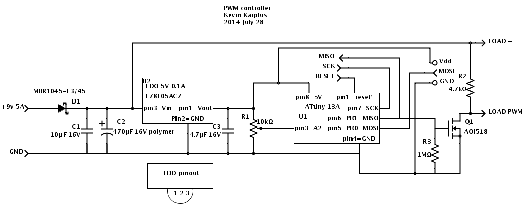
PWM controller using ATtiny 13A
The design I came up with uses a low-dropout regulator to provide 5V for the ATtiny13A. A potentiometer provides analog input and a nFET provides a low-resistance switch for the output. I used the AOI518, because I have some on hand, but they are reaching the “end of life” so some other nFET may need to be used in a future design (perhaps one of the others in the series, such as the AOI516 which has a slightly lower on-resistance but a slightly higher gate capacitance).
The capacitors C1 and C2 are to keep the switching of the large load from propagating spikes into power supply. The 470µF capacitor with a 5A current spike should limit the voltage slew to 10.6V/ms—with a 4.7kHz current square wave, this would be about a 1.1V triangle wave. A polymer electrolytic is used (despite the price) to keep the effective series resistance small. The one I’m using has an ESR of 9mΩ (@100kHz) and a ripple current up to 6.1A. The leakage current could be as high as 1.5mA though. C1 is a small ceramic capacitor to remove higher-frequency noise. The big Schottky diode on the input is just to provide protection against accidentally hooking the circuit up backwards. I should probably add a 60¢ resettable fuse as well, to keep the current from getting excessive if there is a short.
When there is no load, the maximum current draw is 1.9mA for the pullup resistor R2, 0.9mA for the pot, 4–6mA for the ATtiny13A, and up to 1.5mA for C2, for a total of 8.3–10.3mA. With a typically 80% efficient 9v switching power supply, this is a waste of about 100mW, or about 0.9kWh/year.
The pullup resistor R2 is not strictly necessary, but was added to keep the PWM pulses clean, turning all the way off even when the load had only tiny current draw—otherwise I could not get very low duty-cycle pulses to work well—the nFET acted as if it were a 1.3nF capacitor and kept a low voltage even when the nFET was off. With the 4.7kΩ pullup, the voltage goes up appropriately, with a time constant of about 6µs.
So far, I’ve not tried the circuit with a large load—just with a small load that takes 13mA. With that tiny a load, I don’t see any ripple in the power supply from the PWM. With a 210mA load, the ripple on the power supply is noticeable: on top of the 20mV of ripple at about 20MHz with no load, I see 30mV of ripple synchronized with the switching of the PWM, when switching 210mA with a duty cycle of 1/2. Without the 470µF polymer capacitor, the synchronized ripple is more like 200mV, indicating that the capacitor is indeed smoothing out the ripple.
The 30mV swing on 210mA implies that I should see about a 710mV swing if switching 5A. That shouldn’t cause a problem in my design, but I do need to allow a little more voltage so that the swing isn’t a problem. I could also use a bigger capacitor, but the polymer electrolytics are a bit expensive, and the regular wet electrolytics can’t handle a big ripple current—one with the same 6A ripple current rating would be 20 times the volume and 3 times the price of the polymer capacitor.
The high-frequency noise is almost certainly coming from the ATtiny, as it is synchronized with the PWM signal. The 5V power supply at the ATtiny is showing a 40mV ripple, which is large considering that there is a bypass capacitor on the Vdd pin. There is a lot of inductance from the wiring on the board though, which could be increasing the propagation of the high-frequency noise.
Filed under:
Uncategorized Tagged:
Arduino,
ATtiny,
PWM 


 For [Tony]‘s entry for The Hackaday Prize,
  The project featured in this post is an entry in