


Posts with «arduino» label


DIY Canon Intervalometer using Arduino

An intervalometer allows you to take photos at set intervals to view a slow process in super fast speed. Watching paint dry is just as boring in fast motion as it is at normal speed, however, when you point your camera to the clouds in the sky, you can get some amazing effects.
By taking a picture every 3 seconds, and then playing the sequence back at 30 frames a second, you will get to see a 10 minute event in just 7 seconds.To get a nice flowing motion picture, you need to get a good balance between the recording frame rate, and the play-back frame rate.

The recording frame rate is limited by the amount of memory you have in your camera, the length of the captured event, battery charge, and the camera's general capabilities. The playback frame rate needs to be fast enough to prevent jittering, but not so fast that you lose the event in a blink of an eye. The more you practice with different subject matters, the more you get a feel for how long you need to keep the camera running and how long to leave between shots.
When taking pictures of the clouds, you can generally use a 3-5 second frame rate, depending on their speed across the sky. To capture the flow of traffic, I would recommend a picture every 1-2 seconds. However, for really slow events like a plant growing, you may need to extend the frame capture rate significantly. You will get a better idea once you try it for yourself.

This tutorial follows on from the Arduino selfie tutorial, so you might notice some similarities. However, in this tutorial, we will have more control over the intervalometer by using a sliding potentiometer and an LED bar. The pin layout is slightly different from the Arduino Selfie tutorial - so best to start from scratch to avoid pin misconfigurations.
By taking a picture every 3 seconds, and then playing the sequence back at 30 frames a second, you will get to see a 10 minute event in just 7 seconds.To get a nice flowing motion picture, you need to get a good balance between the recording frame rate, and the play-back frame rate.
The recording frame rate is limited by the amount of memory you have in your camera, the length of the captured event, battery charge, and the camera's general capabilities. The playback frame rate needs to be fast enough to prevent jittering, but not so fast that you lose the event in a blink of an eye. The more you practice with different subject matters, the more you get a feel for how long you need to keep the camera running and how long to leave between shots.
When taking pictures of the clouds, you can generally use a 3-5 second frame rate, depending on their speed across the sky. To capture the flow of traffic, I would recommend a picture every 1-2 seconds. However, for really slow events like a plant growing, you may need to extend the frame capture rate significantly. You will get a better idea once you try it for yourself.
This tutorial follows on from the Arduino selfie tutorial, so you might notice some similarities. However, in this tutorial, we will have more control over the intervalometer by using a sliding potentiometer and an LED bar. The pin layout is slightly different from the Arduino Selfie tutorial - so best to start from scratch to avoid pin misconfigurations.
Warning : Any circuit you build for your camera (including this one) is at your own risk. I will not take responsibility for any damage caused to any of your equipment.
I found out that my Canon Powershot SX50 HS camera has a port on the side for a remote switch. In the "Optional Accessories" section of the camera brochure, it identifies the remote switch model as RS-60E3. I then looked up the model number on this website to find out the size of the jack (3 core, 2.5mm), and the pinout (Ground, focus and shutter) required to emulate the remote switch. Once I had this information, I was able to solder some really long wires to the jack and connect up the circuit (as described below).
I use Time-Lapse tool to stitch all of the pictures together to create a movie/animation.
You will need to download and install the LED_Bar library from Seeedstudio into your Arduino IDE libraries folder in order to use the LED Bar in this tutorial. For more information about the LED Bar - visit the LED Bar Seeed-Studio wiki.
Parts Required:
- Freetronics Eleven or (Arduino UNO compatible board)
- Grove Base Shield
- Grove Sliding Potentiometer
- Grove LED Bar
- Grove Universal 4 Pin 20cm Cable
- 4 Channel Relay Module
- 2x 330 ohm resistors
- 2 x diodes
- breadboard
- Jumper Wires (male to male)
- Jumper Wires (female to male)
- Canon Powershot SX50 HS - (here is the brochure)
- Three core, 2.5 mm Jack
Fritzing Sketch
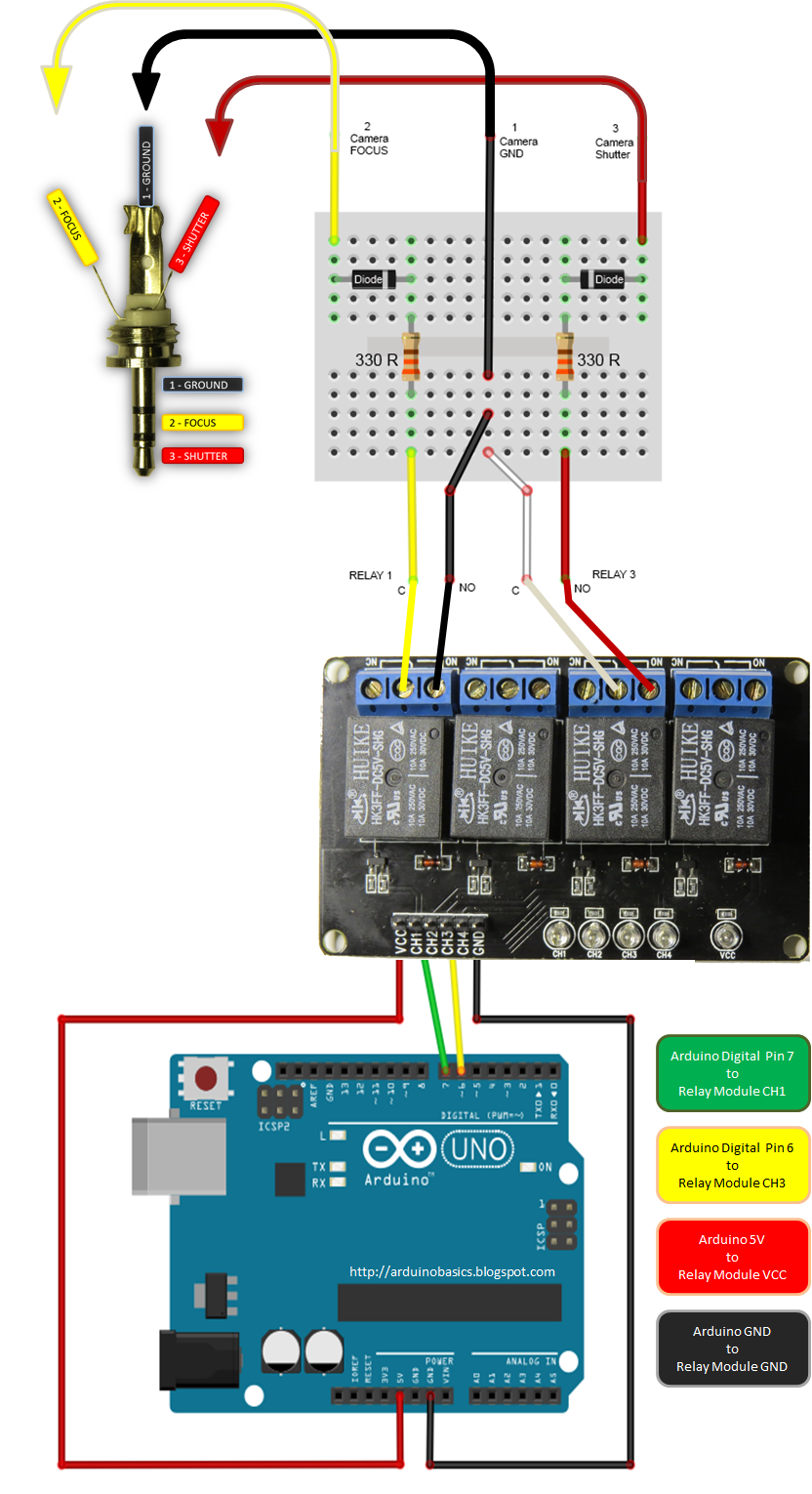
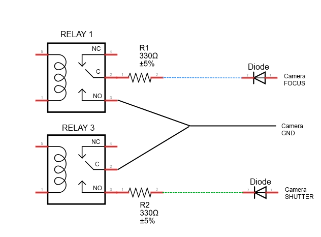


Connection Tables
Arduino to Relay Module:

Relay Module to Camera:
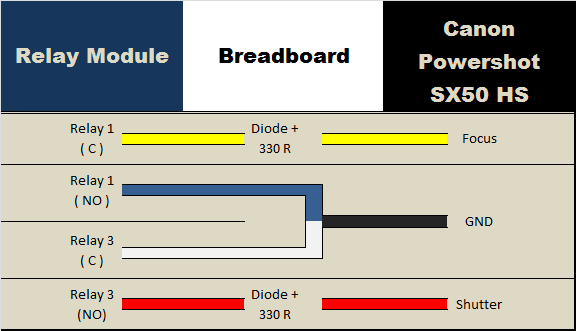
Arduino to Slide Potentiometer:

Arduino to LED Bar:
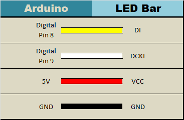
Arduino Sketch
1 |
|
The Video

This project shows how to make your Canon Powershot SX50 HS a whole lot smarter using an Arduino. There are so many things that look so different with an intervalometer. While I connected a slide potentiometer to the Arduino to provide extra flexibility, and an LED Bar for visual feedback, there are many other sensors out there that can be combined with the camera. For example, you could use a PIR sensor to take a picture when movement is detected. Or take a picture when a laser trip-wire is broken. What about sound activation, light activation, leak detection.... the options are limitless.
This has been one of my favorite projects, it was a lot of fun, and very interesting.
I highly recommend that you try it out!
This has been one of my favorite projects, it was a lot of fun, and very interesting.
I highly recommend that you try it out!
If you like this page, please do me a favour and show your appreciation :
Visit my ArduinoBasics Google + page.
Follow me on Twitter by looking for ScottC @ArduinoBasics.
Have a look at my videos on my YouTube channel.
Visit my ArduinoBasics Google + page.
Follow me on Twitter by looking for ScottC @ArduinoBasics.
Have a look at my videos on my YouTube channel.

Feel free to share this page with your friends in any way you see fit.
Snapshots from Maker Faire Rome 2014!
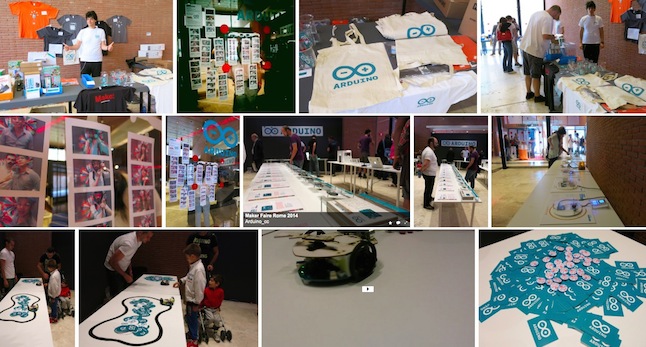
Last weekend the second edition of Maker Faire Rome – The European Edition, hosted 90,000 people (15,000 young boys and girls!) at the Auditorium Parco della Musica, discovering more than 600 maker projects, participated to workshops and attended the conferences and many light-talks.
Take a look at some snapshots on our Flickr account: we took them during the faire at the Arduino Booth and Store (also behind the scene), the Arduino Activities and the presentations announcing the State of Arduino and CasaJasmina – the open source connected home – curated by Bruce Sterling. During the long and intense weekend Arduino participated also to the press conference and vernissage of the exhibition 50 years of italian inventions, from Programma 101 to the first 3d printed car, a project by Make in Italy CDB foundation.

In the next weeks we are going to share some videos of the presentations and the events of those amazing days! Thanks for participating to Maker Faire Rome! Stay tuned…
Do you have any picture to share about the event? Post the link in the comments!
Brushless Motor Controller Shield for Arduino
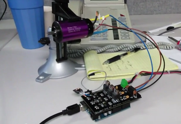
Brushless motors are ubiquitous in RC applications and robotics, but are usually driven with low-cost motor controllers that have to be controlled with RC-style PWM signals and don’t allow for much customization. While there are a couple of open-source brushless drivers already available, [neuromancer2701] created his own brushless motor controller on an Arduino shield.
[neuromancer2701]‘s shield is a sensorless design, which means it uses the back-EMF of the motor for feedback rather than hall effect sensors mounted on the motor. It may seem strange to leave those sensors unused but this allows for less expensive sensorless motors to work with the system. It also uses discrete FETs instead of integrated driver ICs, similar to other designs we have covered. Although he is still working on the back-EMF sensing in his firmware, the shield successfully drives a motor in open-loop mode.
The motor controller is commanded over the Arduino’s serial interface, and will support a serial interface to ROS (Robot Operating System) in the future. This shield could be a good alternative to hobby RC controllers for robots that need a customizable open-source motor controller. The PCB design and source code are available on GitHub.
Filed under: Arduino Hacks


The Effects are IN the Guitar? It’s so Simple…

We’ve all had that problem. Up on stage, rocking out Jimi Hendrix-style on guitar with your band, but frustrated at having to mess around with foot pedals to control all of the effects. [Richard] solved this problem in a unique way: he put a preamp and a microcontroller in a guitar that can create some very interesting effects.
For the musically challenged, electric guitars often have several sets of electromagnetic pickups that detect vibrations in the strings at different points along the strings. Selecting different pickup combinations with a built-in switch changes the sound that the guitar makes. [Richard] wired the pickups in his Fender Stratocaster to the microcontroller and programmed it to switch the pickups according to various patterns. The effect is somewhat like a chorus pedal at times and it sounds very unique.
The volume and tone knobs on the guitar are used to select the programmed patterns to switch various pickups at varying speeds. This has the added bonus of keeping the stock look of the guitar in tact, unlike some other guitars we’ve seen before. The Anubis preamp, as it is called, is a very well polished project and the code and wiring schematic are available on the project site along with some audio samples.
Filed under: musical hacks


Internet-Connected TI-84
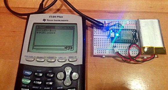
Just before the days where every high school student had a cell phone, everyone in class had a TI graphing calculator. In some ways this was better than a cell phone: If you wanted to play BlockDude instead of doing trig identities, this was much more discrete. The only downside is that the TI calculators can’t easily communicate to each other like cell phones can. [Christopher] has solved this problem with his latest project which provides Wi-Fi functionality to a TI graphing calculator, and has much greater aspirations than helping teenagers waste time in pre-calculus classes.
The boards are based around a Spark Core Wi-Fi development board which is (appropriately) built around a TI CC3000 chip and a STM32F103 microcontroller. The goal of the project is to connect the calculators directly to the Global CALCnet network without needing a separate computer as a go-between. These boards made it easy to get the original Arduino-based code modified and running on the new hardware.
After a TI-BASIC program is loaded on the graphing calculator, it is able to input the credentials for the LAN and access the internet where all kinds of great calculator resources are available through the Global CALCnet. This is a great project to make the math workhorse of the classroom even more useful to students. Or, if you’re bored with trig identities again, you can also run a port of DOOM.
Filed under: wireless hacks


Web Browser Pushes Arduino’s Limits
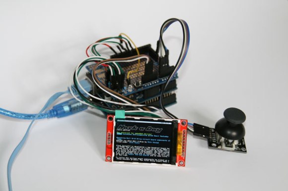
Some projects that we build fulfill a genuine need for a new piece of hardware or software that will make life easier or fix a common problem. Other projects, on the other hand, we do just because it’s possible to do. [Gilchrist] has finished work on a project that fits squarely in the second category: a web browser that runs exclusively on an Arduino Uno with an ethernet shield.
The Arduino can serve plain-text web pages to an attached LCD and can follow hyperlinks. User input is handled by a small joystick, but the impressive part of the build is on the software side. The Arduino only has 2KB of RAM to handle web pages, and the required libraries take up 20KB of memory, leaving only about 12 KB for the HTML parser/renderer and the LCD renderer.
The Arduino browser is a work in progress, and [Gilchrist] mentions that goals for the project include more robustness to handle poor HTML (the Hackaday retro edition loads flawlessly though), a terminal, and WiFi capabilities. To that end, maybe a good solution would be using the new ESP8266 chip to keep things small and inexpensive?
Filed under: Arduino Hacks


The ESP8266 Becomes a Terrible Browser
The ESP8266 are making their way over from China and onto the benches of tinkerers around the world for astonishing web-enabled blinking LED projects and the like. [TM] thought he could do something cooler with his WiFi to UART module and decided to turn one into a web browser.
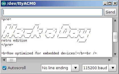
There’s no new code running on the ESP8266 – all the HTML is being pushed through an Arduino Mega, requesting data from a server (in this case our fabulous retro edition), and sending the data to the Arduino serial console. The connection is first initiated with a few AT commands to the ESP module, then connecting to the retro server and finally dumping everything received to the console.
It’s not much – HTML tags are still displayed, and images are of course out of the question. The result, however, isn’t that much different from what you would get from Lynx, meaning now the challenge is open for an Arduino port of this ancient browser.
Filed under: Arduino Hacks, wireless hacks


Announcing a wearable collaboration with Adafruit: Arduino Gemma
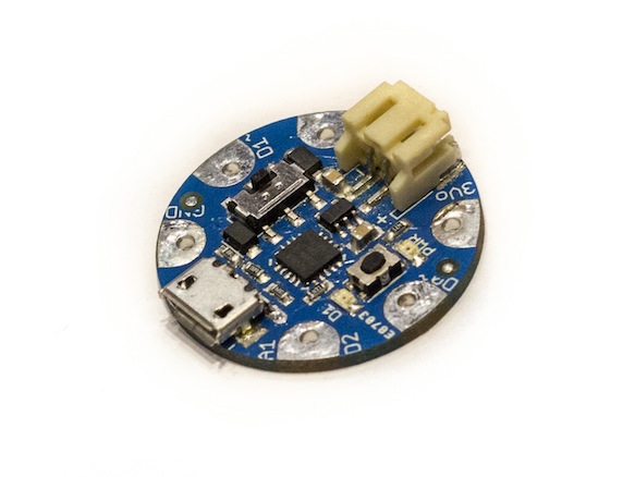
Arduino Gemma preview – Final board coming late autumn
During his saturday morning presentation at Maker Faire Rome, Massimo Banzi gave a preview of a new collaboration and a new board: Adafruit Gemma becomes officially Arduino Gemma, a tiny but powerful wearable microcontroller board in a 27mm diameter package.
Powered by an Attiny85 and programmable with the Arduino IDE over USB, anyone will be able to easily create wearable projects with all the advantages of being part of the Arduino family. The board will be default-supported in the Arduino IDE, equipped with an on/off switch and a microUSB connector.


The Attiny85 is a great processor because despite being so small, it has 8K of flash and 5 I/O pins, including analog inputs and PWM ‘analog’ outputs. It was designed with a USB bootloader so you can plug it into any computer and reprogram it over a USB port (it uses 2 of the 5 I/O pins, leaving you with 3). Ideal for small & simple projects sewn with conductive thread, the Arduino Gemma fits the needs of most of entry-level wearable creations including reading sensors and driving addressable LED pixels.
After the fruitful joint effort developing Arduino Micro, once more the Arduino Gemma has been developed in collaboration with Adafruit Industries, one of the main leaders of the Maker movement. Arduino Gemma will be available for purchase on the Arduino Store and Adafruit Industries starting late autumn 2014.
Technical specifications:
Microcontroller: ATtiny85
Operating Voltage: 3.3V
Input Voltage (recommended): 4-16V via battery port
Input Voltage (limits): 3-18V
Digital I/O Pins: 3
PWM Channels: 2
Analog Input Channels: 1
DC Current per I/O Pin: 40 mA
DC Current for 3.3V Pin: 150 mA
Flash Memory: 8 KB (ATtiny85) of which 2.5 KB used by bootloader
SRAM: 0.5 KB (ATtiny85)
EEPROM: 0.5 KB (ATtiny85)
Clock Speed: 8 MHz
MicroUSB for USB Bootloader
JST 2-PH for external battery
The Tah Bluetooth stick lets you control (almost) anything with a smartphone

We've seen plenty of development boards, but this might be the first that comes with both Bluetooth LE and built-in USB. Tah is the creation of India's Revealing Hour and has been designed to both lower the cost of adding Bluetooth to Arduino projects, but also to connect your smartphone to other devices in the home. For instance, adding an IR shield will enable you to create a universal remote control for appliances and your TV. Even better, is that you can slot the hardware into your games console and use your smartphone as a controller -- in the video embedded after the break, the company uses a smartphone as a substitute PlayStation controller, and there's an Xbox variant that's currently being developed. Naturally, Tah is currently gathering funds over at CrowdSupply, and its makers need $25,000 to begin manufacturing. If you'd like to get your hands on one, then early-bird customers can snag one for $40, while the late-comers will pay 10 dollars more.
Filed under: Wireless
Source: CrowdSupply