I have been working on a new interface board for the Jetson TK1 embedded supercomputer called the Jetduino. It makes it very easy to build robots that can use the parallel processing capabilites of the NVIDIA GPU for vision and neural neural networks.
Take three NRF24L0+ radios, two Arduino Nanos, and a Raspberry Pi. Add a bored student and a dorm room at Rice University. What you get is the RRAD: Rice Ridiculously Automated Dorm. [Jordan Poles] built a modular system inspired by BRAD (the Berkeley Ridiculously Automated Dorm).
RRAD has three types of nodes:
Actuation nodes – Allows external actuators like relays or solenoids
Sensory nodes – Reports data from sensors (light, temperature, motion)
Hub nodes – Hosts control panel, records data, provides external data interfaces
The hub also allows [Jordan] to control things with his Android phone with Tasker. He has the Arduino and Raspberry Pi code on GitHub if you want to ridiculously automate something of your own. You’d probably want to adapt it to your dorm room, house, or RV, though.
[Jordan] continues to work on the project and promises to have voice recognition and other features, soon. We cover a lot of home automation projects including some others described as ridiculous. The video below shows BRAD, the inspiration for RRAD.
Direct-digital synthesis (DDS) is a sample-playback technique that is useful for adding a little bit of audio to your projects without additional hardware. Want your robot to say ouch when it bumps into a wall? Or to play a flute solo? Of course, you could just buy a cheap WAV playback shield or module and write all of the samples to an SD card. Then you wouldn’t have to know anything about how microcontrollers can produce pitched audio, and could just skip the rest of this column and get on with your life.
~45db signal to noise ratio from an Arduino
But that’s not the way we roll. We’re going to embed the audio data in the code, and play it back with absolutely minimal additional hardware. And we’ll also gain control of the process. If you want to play your samples faster or slower, or add a tremolo effect, you’re going to want to take things into your own hands. We’re going to show you how to take a single sample of data and play it back at any pitch you’d like. DDS, oversimplified, is a way to make these modifications in pitch possible even though you’re using a fixed-frequency clock.
The same techniques used here can turn your microcontroller into a cheap and cheerful function generator that’s good for under a hundred kilohertz using PWM, and much faster with a better analog output. Hackaday’s own [Bil Herd] has a nice video post about the hardware side of digital signal generation that makes a great companion to this one if you’d like to go that route. But we’ll be focusing here on audio, because it’s easier, hands-on, and fun.
We’ll start out with a sample of the audio that you’d like to play back — that is some data that corresponds to the voltage level measured by a microphone or something similar at regular points in time. To play the sample, all we’ll need to do is have the microcontroller output these voltages back at exactly the same speed. Let’s say that your “analog” output is via PWM, but it could easily be any other digital-to-analog converter (DAC) of your choosing. Each sample period, your code looks up a value and writes it out to the DAC. Done!
(In fact, other than reading the data from an SD card’s filesystem, and maybe having some on-board amplification, that’s about all those little WAV-player units are doing.)
Pitch Control
In the simplest example, the sample will play back at exactly the same pitch it was recorded if the sample playback rate equals the input sampling rate. You can make the pitch sound higher by playing back faster, and vice-versa. The obvious way to do this is to change the sample-playback clock. Every period you play back one the next sample, but you change the time between samples to give you the desired pitch. This works great for one sample, and if you have infinitely variable playback rates available.
Woof!
But let’s say that you want to take that sample of your dog barking and play Beethoven’s Fifth with it. You’re going to need multiple voices playing the sample back at different speeds to make the different pitches. Playing multiple pitches in this simplistic way, would require multiple sample-playback clocks.
Here’s where DDS comes in. The idea is that, given a sampled waveform, you can play nearly any frequency from a fixed clock by skipping or repeating points of the sample as necessary. Doing this efficiently, and with minimal added distortion, is the trick to DDS. DDS has its limits, but they’re mostly due to the processor you’re using. You can buy radio-frequency DDS chips these days that output very clean sampled sine waves up to hundreds of megahertz with amazing frequency stability, so you know the method is sound.
Example
Let’s make things concrete with a simplistic example. Say we have a sample of a single cycle of a waveform that’s 256 bytes long, and each 8-bit byte corresponds to a single measured voltage at a point in time. If we play this sample back at ten microseconds per sample we’ll get a pitch of 1 / (10e-06 * 256) = 390.625 Hz, around the “G” in the middle of a piano.
Imagine that our playback clock can’t go any faster, but we’d nonetheless like to play the “A” that’s just a little bit higher in pitch, at 440 Hz. We’d be able to play the “A” if we had only sampled 227 bytes of data in the first place: 1 / (10e-06 * 227) = 440.53, but it’s a little bit late to be thinking of that now. On the other hand, if we just ignored 29 of the samples, we’d be there. The same logic works for playing lower notes, but in reverse. If some samples were played twice, or even more times, you could slow down the repetition rate of the cycle arbitrarily.
In the skipping-samples case, you could just chop off the last 29 samples, but that would pretty seriously distort your waveform. You could imagine spreading the 29 samples throughout the 256 and deleting them that way, and that would work better. DDS takes this one step further by removing different, evenly spaced samples with each cycle through the sampled waveform. And it does it all through some simple math.
The crux is the accumulator. We’ll embed the 256 samples in a larger space — that is we’ll create a new counter with many more steps so that each step in our sample corresponds to many numbers in our larger counter, the accumulator. In my example code below, each of the 256 steps gets 256 counts. So to advance one sample per period, we need to add 256 to the larger counter. To go faster, you add more than 256 each period, and to go slower, add less. That’s all there is to it, except for implementation details.
In the graph here, because I can’t draw 1,024 tick marks, we have 72 steps in the accumulator (the green outer ring) and twelve samples (inner, blue). Each sample corresponds to six steps in the accumulator. We’re advancing the accumulator four steps per period (the red lines) and you can see how the first sample gets played twice, then the next sample played only once, etc. In the end, the sample is played slower than if you took one sample per time period. If you take more than six steps in the increment, some samples will get skipped, and the waveform will play faster.
Implementation and Build
So let’s code this up and flash it into an Arduino for testing. The code is up at GitHub for you to follow along. We’ll go through three demos: a basic implementation that works, a refined version that works a little better, and finally a goofy version that plays back single samples of dogs barking.
Filter “circuit”
In overview, we’ll be producing the analog output waveforms using filtered PWM, and using the hardware-level PWM control in the AVR chip to do it. Briefly, there’s a timer that counts from 0 to 255 repeatedly, and turns on a pin at the start and turns it off at a specified top value along the way. This lets us create a fast PWM signal with minimal CPU overhead, and it uses a timer.
Still some jaggies left. Could use better filter.
We’ll use another timer that fires off periodically and runs some code, called an interrupt service routine (ISR), that loads the current sample into the PWM register. All of our DDS code will live in this ISR, so that’s all we’ll focus on.
If this is your first time working directly with the timer/counters on a microcontroller, you’ll find some configuration code that you don’t really have to worry about. All you need to know is that it sets up two timers: one running as fast as possible and controlling a PWM pin for audio output, and another running so that a particular chunk of code is called consistently, 24,000 times per second in this example.
So without further ado, here’s the ISR:
struct DDS {
    uint16_t increment;
    uint16_t position;
    uint16_t accumulator;
    const int8_t* sample;   /* pointer to beginning of sample in memory */
};
volatile struct DDS voices[NUM_VOICES];

ISR(TIMER1_COMPA_vect) {
    int16_t total = 0;

    for (uint8_t i = 0; i < NUM_VOICES; i++) {
        total += (int8_t) pgm_read_byte_near(voices[i].sample + voices[i].position);

        /* Take an increment step */
        voices[i].accumulator += voices[i].increment;
        voices[i].position += voices[i].accumulator / ACCUMULATOR_STEPS;
        voices[i].accumulator = voices[i].accumulator % ACCUMULATOR_STEPS;
        voices[i].position = voices[i].position % SAMPLE_LENGTH;
    }

    total = total / NUM_VOICES;
    OCR2A = total + 128; // add in offset to make it 0-255 rather than -128 to 127
}
The first thing the code does is to define a (global) variable that will hold the state of each voice for as many voices as we want, defined by NUM_VOICES. Each voice has an increment which determines how many steps to take in the accumulator per sample output. The position keeps track of exactly which of the 256 samples in our waveform data is currently playing, and the accumulator keeps track of the rest. Here, we’re also allowing for each voice to play back a different waveform table from memory, so the code needs to keep track of the address where each sample begins. Changing which sample gets played back is as simple as pointing this variable to a different memory location, as we’ll see later. For concreteness, you can imagine this sample memory to contain the points in a sine wave, but in practice any repetitive waveform will do.
So let’s dive into the ISR, and the meat of the routine. Each update cycle, the sum of the output on the different voices is calculated in total. For each voice, the current sample is read from memory, added to the total and then incremented to the next step. Here we get to see how the accumulator works. The increment variable is added to the accumulator. When the accumulator is larger than the number of steps per sample, the position variable gets moved along. Next, the accumulator is shrunk back down to just the remainder of the un-accounted-for values using the modulo operator, and the sample position is wrapped around if necessary with another modulo.
Division?? Modulo??
If you’ve worked with microcontrollers before, alarm bells may be going off in your head right now. The AVR doesn’t have a built-in division routine, so that could take a lot of CPU power. And the modulo operator is even worse. That is, unless the divisor or modulo are powers of two. In those cases, the division is the same as shifting the binary number to the right by the number of bits in the power of two.
A similar operation makes the modulo tolerable. If, for instance, you want a number to be modulo eight, you can simply drop all of the binary bits that correspond to values eight and higher. So, x % 8 can be implemented as x & 0b00000111 where this logical-ANDing just keeps the least-significant three bits. If you’re not in tune with your inner bit-flipper, this can be viewed as a detail — but just know that division and modulo aren’t necessarily bad news if your compiler knows how to implement them efficiently when you choose powers of two for the divisors.
And that gets us to the end of the routine. The sample values were added together, so now they need dividing by the number of voices and centering around the mid-point to fit inside the 8-bit range that the PWM output register requires. As soon as this value is loaded into memory, the PWM hardware will take care of outputting the right waveform on its next cycle.
Refinements
The ISR above is already fairly streamlined. It’s avoided the use of any if statements that would otherwise slow it down. But it turns out we can do better, and this optimized form is often the way you’ll see DDS presented. Remember, we’re running this ISR (in this example) 24,000 times per second — any speedup inside the ISR makes a big difference in overall CPU usage.
The first thing we’ll do is make sure that we have only 256 samples. That way, we can get rid of the line where we limit the sample index to being within the correct range simply by using an 8-bit variable for the sample value. As long as the number of bits in the sample index matches the length of the sample, it will roll over automatically.
We can use the same logic to merge the sample and accumulator variables above into a single variable. If we have an 8-bit sample and an 8-bit accumulator, we combine them into a 16-bit accumulator where the top eight bits correspond to the sample location.
struct DDS {
    uint16_t increment;
    uint16_t accumulator;
    const int8_t* sample;   /* pointer to beginning of sample in memory */
};
volatile struct DDS voices[NUM_VOICES];

ISR(TIMER1_COMPA_vect) {
    int16_t total = 0;

    for (uint8_t i = 0; i < NUM_VOICES; i++) { total += (int8_t) pgm_read_byte_near(voices[i].sample + (voices[i].accumulator >> 8));
        voices[i].accumulator += voices[i].increment;
    }
    total = total / NUM_VOICES;
    OCR2A = total + 128; // add in offset to make it 0-255 rather than -128 to 127
}
You can see that we’ve dropped the position value from the DDS structure entirely, and that the ISR is significantly streamlined in terms of lines of code. (It actually runs about 10% faster too.) Where previously we played the sample at sample + position, we are now playing the sample at sample + (accumulator >> 8). This means that the effective position value will only advance once every 256 steps of the increment — the high eight bits only change once all of the low 256 steps have been stepped through.
None of this is strange if you think about it in base 10, by the way. You’re used to counting up to 99 before the third digit flips over to 100. Here, we’re just using the most-significant bits to represent the sample step, and the number of least-significant bits determines how many increments we need to make before a step is taken. This method is essentially treating the 16-bit accumulator as a fixed-point 8.8 position value, if that helps clear things up. (If not, I’m definitely going to write something on fixed-point math in the future.) But that’s the gist of it.
This is the most efficient way that I know to implement a DDS routine on a processor with no division, but that’s capable of doing bit-shifts fairly quickly. It’s certainly the classic way. The catch is that both the number of samples has to be a power of two, the number of steps per sample has to be a power of two, and the sum of both of them has to fit inside some standard variable type. In practice, this often means 8-bit samples with 8-bit steps or 16-bit samples with 16-bit steps for most machines. On the other hand, if you only have a 7-bit sample, you can just use nine bits for the increments.
Goofing Around: Barking Dogs
As a final example, I’d like to run through the same thing again but for a simple sample-playback case. In the demos above we played repeating waveforms that continually looped around on themselves. Now, we’d like to play a sample once and quit. Which also brings us to the issue of starting and stopping the playback. Let’s see how that works in this new ISR.
struct Bark {
    uint16_t increment = ACCUMULATOR_STEPS;
    uint16_t position = 0;
    uint16_t accumulator = 0;
};
volatile struct Bark bark[NUM_BARKERS];

const uint16_t bark_max = sizeof(WAV_bark);

ISR(TIMER1_COMPA_vect) {
    int16_t total = 0;

    for (uint8_t i = 0; i < NUM_BARKERS; i++) {
        total += (int8_t)pgm_read_byte_near(WAV_bark + bark[i].position);

        if (bark[i].position < bark_max){    /* playing */
            bark[i].accumulator += bark[i].increment;
            bark[i].position += bark[i].accumulator / ACCUMULATOR_STEPS;
            bark[i].accumulator = bark[i].accumulator % ACCUMULATOR_STEPS;
        } else {  /*  done playing, reset and wait  */
            bark[i].position = 0;
            bark[i].increment = 0;
        }
    }
    total = total / NUM_BARKERS;
    OCR2A = total + 128; // add in offset to make it 0-255 rather than -128 to 127
}
The code here is broadly similar to the other two. Here, the wavetable of dogs barking just happened to be 3,040 samples long, but since we’re playing the sample once through and not looping around, it doesn’t matter so much. As long as the number of steps per position (ACCUMULATOR_STEPS) is a power of two, the division and modulo will work out fine. (For fun, change ACCUMULATOR_STEPS to 255 from 256 and you’ll see that the whole thing comes crawling to a stop.)
The only difference here is that there’s an if() statement checking whether we’ve finished playing the waveform, and we explicitly set the increment to zero when we’re done playing the sample. The first step in the wavetable is a zero, so not incrementing is the same as being silent. That way, our calling code only needs to set the increment value to something non-zero and the sample will start playing.
If you haven’t already, you should at least load this code up and look through the main body to see how it works in terms of starting and stopping, playing notes in tune, and etcetera. There’s also some thought that went into making the “synthesizer” waveforms in the first examples, and into coding up sampled waveforms for use with simple DDS routines like this. If you’d like to start off with a sample of yourself saying “Hackaday” and running that in your code, you’ll find everything you need in the wave_file_generation folder, written in Python. Hassle me in the comments if you get stuck anywhere.
Conclusion
DDS is a powerful tool. Indeed, it’s more powerful than we’ve even shown here. You can run this exact routine at up to 44 kHz, just like your CD player, but of course at an 8-bit sample depth instead of 16. You’ll have to settle for two or three voices instead of four because that speed is really taxing the poor little AVR inside an Uno. With a faster CPU, you can not only get out CD-quality audio, but you can do some real-time signal processing on it as well.
And don’t even get me started on what chips like the Analog Devices high-speed DDS chips that can be had on eBay for just a few dollars. They’re doing the exact same thing, for a sinewave, at very high speed and frequency accuracy. They’re a far cry from implementing DDS in software on an Arduino to make dogs bark, but the principle is the same.
Worse for Wear is a clothing company for women who ride motorcycles. The fascinating clothing they produce is very fashionable, comfortable, and needs to protect riders from impact and abrasion if they have an accident. Jackets and trousers have knee and hip pads included to protect the rider when sliding many meters across asphalt. That’s why the fabric must be strong and abrasion resistant because if the fabric wears away too quickly, the rider’s skin will be exposed and injured.
To choose the perfect fabric, Scott and Laura, co-founders of the company, created an Impact Abrasion Resistance Testing Machine running on Arduino Uno to perform tests on different materials like knit fabrics, woven fabrics, and leather, to see how long it takes before the material is sanded completely through. I interviewed them to learn more about it!
- What is the impact abrasion resistance testing machine and how does it work?
When selecting fabric to use in our clothes, we have to make sure that it is strong and abrasion resistant. We use the impact abrasion resistance test machine to determine which fabrics will withstand abrasion (scraping and sliding) the best. It is important to us to test the fabrics ourselves and not rely solely on the claims of fabric manufacturers.
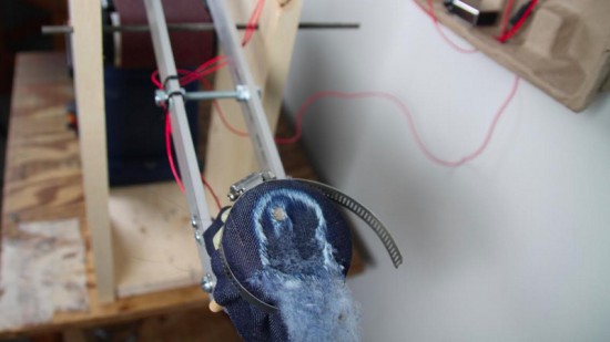
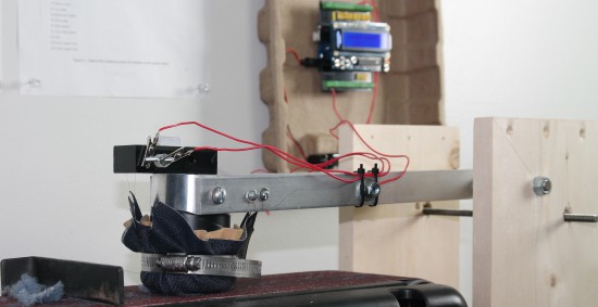
The machine has a weighted arm, like a hammer, suspended above an abrasive belt sander. A sample of the fabric that we want to test is wrapped around the head of the hammer and then dropped onto the moving sanding belt. An Arduino Uno is used to record the amount of time it takes to sand through the fabric sample.
Check the video below to see how it works:
- Why did you decide to use Arduino?
We have used Lilypad Arduino and Arduino Uno before to prototype some e-textile projects, so it was easy for us to get started on this one with our previous experience. The large number of accessory boards available made it simple to add an informational display and user interface to the machine. In just a few hours, we were able to very quickly create a machine to compare the abrasion resistance of a variety of fabric samples. The simplicity of working with Arduino was a very good choice for us, because our real business is creating clothing, not building test machines!
- What does Arduino control in the machine?
An Arduino Uno is used to record the amount of time it takes to sand through the fabric sample. The method we use is based on European Union standards for motorcycle safety gear testing. To measure the fabric’s abrasion time, we use two thin copper wires (magnet wire). One wire is placed inside and another outside of the fabric sample before everything is wrapped around the head of the hammer. Each wire is then connected to ground on one end and an to input pin on the Arduino on the other end. The pins are in INPUT_PULLUP mode so a current runs through them. The LCD display on the Arduino tells us when both wires are connected properly.
Then, we start the belt sander and drop the hammer onto the spinning sanding belt. The outer wire breaks very quickly, breaking the connection to that pin [ digitalRead(outerWireIn) == HIGH ]. At this point, the Arduino records the start time. When the fabric wears through – usually within a couple of seconds – the inner wire is exposed to the sanding belt and quickly breaks. That marks the end time, which the Arduino records and displays on the LCD shield. A single type of fabric must be tested at least five times in order to make sure our recorded times are accurate.
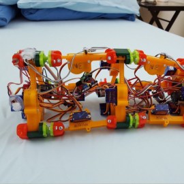
Walking, jumping, rolling, flying, swimming – robotic locomotion is limited only by the imagination of the inventor. [Roger Rabbit] apparently has a pretty vivid imagination, because he’s building robots that move like worms.
Version 1 of [Roger]’s robot is only semi-vermiform and is more of tube climber. It has a pair of 3D-printed pantographs that expand and contract with servos and move along the robot’s axis on a stepper-driven lead screw. An Arduino reads sensors and coordinates the expansion of the pantographs to grip the internal diameter of a pipe and push the worm-bot along. It’s a slow but effective way to get around in the limited confines of a pipe.
The next iteration, dubbed [Wolly], is much more worm-like and not restricted to pipe-running. It has four expandable triangular frames connected to each other with rack-and-pinion backbones. The first frame contracts, the racks push it forward, it expands, the next contracts, and soon it’s doing the worm across the floor. Still slow, but pretty neat to watch, and you can see how it can be steered. It might even be able to roll around its long axis, and it’d make a decent tube climber as well.
This creepy autonomous worm-bot seems very similar to [Wolly], but aside from that we haven’t covered too many robots like these. There’s a lot of thought and effort in these worm-bots, and we’re keen to see where [Roger] takes this unique robot body plan.
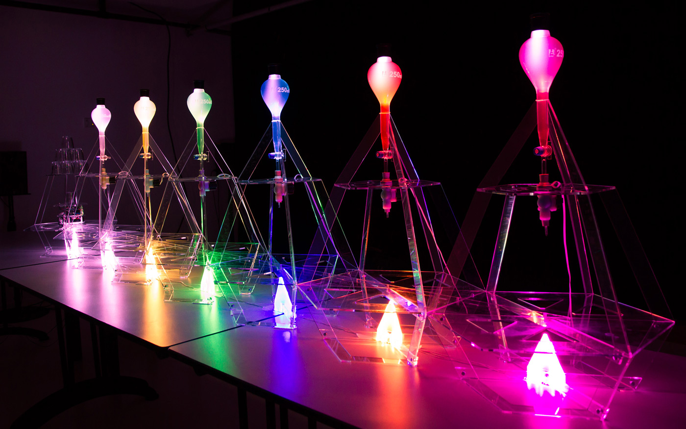
Ever wondered what your tweets would taste like if you could distill them into a drink? Probably not, but there's now a way to find out. Clément Gault and Koi Koi Design have whipped up Data Cocktail, an Arduino-powered machine that creates a drink based on Twitter updates. In its current incarnation, it looks for the five latest tweets mentioning keywords linked to ingredients, and fills the glass accordingly. The result is an original, spur-of-the-moment mix -- it'll even print out the 'recipe' (really, a ratio of the keywords) and thank the users who unwittingly contributed to the beverage.
Ever wondered what your tweets would taste like if you could distill them into a drink? Probably not, but there's now a way to find out. Clément Gault and Koi Koi Design have whipped up Data Cocktail, an Arduino-powered machine that creates a drink based on Twitter updates. In its current incarnation, it looks for the five latest tweets mentioning keywords linked to ingredients, and fills the glass accordingly. The result is an original, spur-of-the-moment mix -- it'll even print out the 'recipe' (really, a ratio of the keywords) and thank the users who unwittingly contributed to the beverage.
Ever wondered what your tweets would taste like if you could distill them into a drink? Probably not, but there's now a way to find out. Clément Gault and Koi Koi Design have whipped up Data Cocktail, an Arduino-powered machine that creates a drink based on Twitter updates. In its current incarnation, it looks for the five latest tweets mentioning keywords linked to ingredients, and fills the glass accordingly. The result is an original, spur-of-the-moment mix -- it'll even print out the 'recipe' (really, a ratio of the keywords) and thank the users who unwittingly contributed to the beverage.
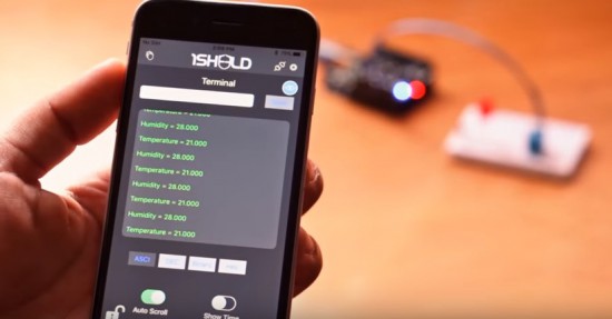
Have you ever thought of turning your iPhone and iPad into a platform of more than 40 Arduino shields? Now it’s possible!
The team of 1Sheeld have officially released the new 1Sheeld for iOS and it’s available for pre-orders for $39 instead of it’s original price $55 (shipping on May 2016).
You can control robots, actuators, display sensors’ data and much more. Take a look at the demo video:
[Mike]’s hacks aren’t breathtaking in their complexity, but they got a good chuckle out of us. [Mike], the CEO of The Useless Duck Company, lives in a hub of innovation somewhere in Canada, where he comes up with useful gadgets such as a Fedora that tips itself, or a door that locks when you’re shopping for gifts for your wife and you’re in incognito mode.
It all started when he was trying to learn the Arduino, and he put quite a few hours into making a device that could wirelessly squeak a rubber bath duck from the bathroom. The whole project reminded us of our first clumsy forays into the world of electronics, with entirely too many parts to complete a simple function. The Arduino being the gateway drug it is, it wasn’t long before he was building a bartending robot.
We hope he continues to construct more entertaining gadgets.


 Version 1 of [Roger]’s robot is only semi-vermiform and is more of