If there’s one thing we’ve learned over the years, it’s that if it’s got a silicon chip inside, it could be carrying a virus. Research by one group focused on hiding a trojan inside an AVR Arduino bootloader, proving even our little hobbyist microcontrollers aren’t safe.
The specific aim of the research was to hide a trojan inside the bootloader of an AVR chip itself. This would allow the trojan to remain present on something like a 3D printer even if the main firmware itself was reinstalled. The trojan would still be able to have an effect on the printer’s performance from its dastardly hiding place, but would be more difficult to notice and remove.
The target of the work was the ATmega328P, commonly used in 3D printers, in particular those using the Marlin firmware. For the full technical details, you can dive in and read the research paper for yourself. In basic terms, though, the modified bootloader was able to use the chip’s IVSEL register to allow bootloader execution after boot via interrupt. When an interrupt is called, execution passes to the trojan-infected bootloader’s special code, before then returning to the program’s own interrupt to avoid raising suspicion. The trojan can also execute after the program’s interrupt code too, increasing the flexibility of the attack.
Simply reflashing a program to an affected chip won’t flush out the trojan. The chip instead must have its bootloader specifically rewritten a clean version to remove the offending code.
It’s not a super dangerous hack, overall. Typically, flashing a malicious bootloader would require physical access to the chip. Furthermore, there’s not heaps to be gained by sneaking code onto the average 3D printer out there. However, it’s nonetheless a good example of what bootloaders can really do, and a reminder of what we should all be careful of when operating in security-conscious domains. Stay safe out there!
After a long period of development, we’re really happy to pass on the announcement that version 2.0.0 of the Arduino IDE is now available. Not only is it a more usable and practical development environment, there’s also some new features such as seamless cloud integration (which you are not forced to used) which makes moving between machines easy. From the arduino website:
We’re pleased to announce that as of today Arduino IDE 2.0 has moved to stable and is available for download. Since the launch of the Beta version back in Spring 2021, the feedback received from the active Arduino community has enabled us to focus on what’s meaningful to the widest user-base. It carries a modern editor and provides a better overall user experience thanks to a responsive interface and faster compilation time.
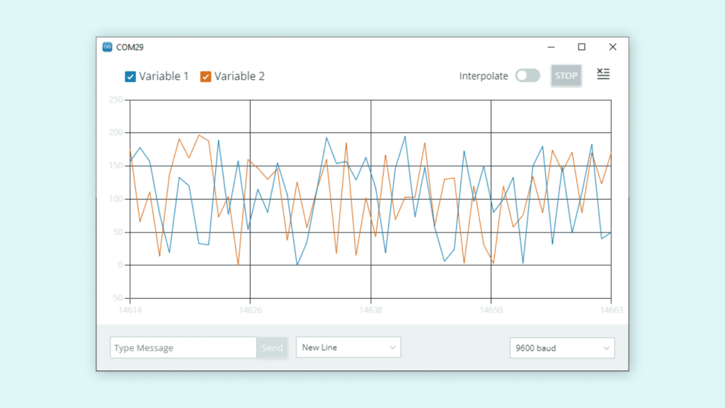
Over and above the core features (we’ll get into those in more details later) the IDE 2.0 benefits from a number of enhancements and additional support. The Serial Monitor and Plotter can be used together, enabling users to have two viewports onto their data output. Before you had to choose between text and graphs, whereas now you can have both.
As well as the refreshed User Interface that provides a more intuitive experience whilst using Arduino IDE 2.0, speed is of the essence. An Arduino-optimized code-completion and code-assist within the language server, help you write code quickly and spot errors as you type. The enormous amount of user feedback allowed us to identify the weakest spots such as code assist and completion, serial output, loading and compilation time. We made it all better now.
A special mention goes out to Paul Stoffregen who has provided enormous feedback to the IDE development team and been actively developing the initial support for advanced third-party platforms such as Teensy for IDE 2.0 (currently experimental).
If you haven’t already given the new IDE 2.0 a try, here are just a few of the key features…
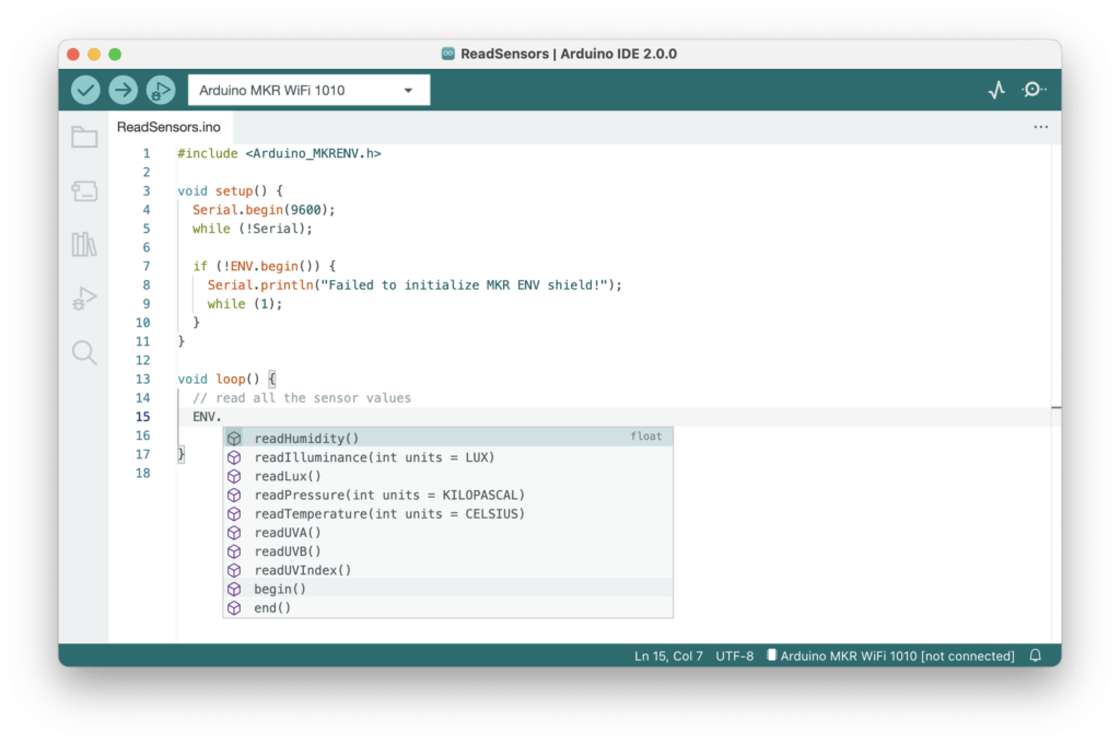
Autocomplete during sketch editing
While typing, the editor can suggest the autocompletion of variables and functions according to your code and the libraries you included:
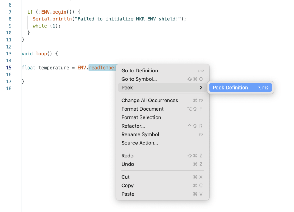
When right-clicking on a variable or a function, a contextual menu will provide navigation shortcuts to jump to the line (and file) where they are declared:
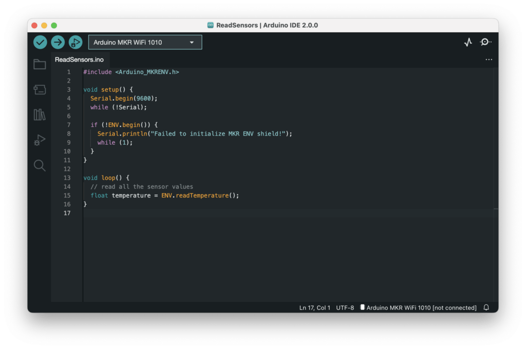
Dark Mode
If your eyes are feeling the strain you can quickly change settings and switch to Dark Mode. Some of you may have used this during the Beta, but our design team has reworked the entire Dark Theme to make it more consistent, beautiful and easy on the eye.
Never lose a sketch keeping them safely at Arduino Cloud
For people who work on multiple computers or want to store their Sketches securely in the Cloud, the Remote Sketchbook integration is a really useful feature.
Easily switch from one computer to another and keep working. If you don’t have Arduino IDE 2.0 installed on all your machines, just open the Arduino Web Editor and you can code from your browser in the online IDE with access to all your sketches and libraries. There’s no need to worry about losing your sketches either, with Remote Sketchbook you only need one click and they will be pushed securely to the Arduino Cloud.
Work offline and sync later, simply bring your sketch down from the Cloud, edit offline and when you are back online click on “Push” and all your changes will be uploaded, meaning all your sketches will always be up-to-date and ready to use.
Serial Plotter
The IDE 2.0 features a richer Serial Plotter that is a versatile tool for tracking different data and variables which are received from your Arduino board. The Serial Plotter is a really useful visual tool that will help you to understand and compare your data points better. It can be used for testing and calibrating sensors, comparing values and other similar scenarios.
In-app updates
Our users have always been accustomed to receiving notifications when new boards’ support or libraries updates were available, and IDE 2.0 is no exception. As a plus, the IDE can now itself be updated when a new version is available, so no need to head to the downloads page anymore: click the button and get the latest and greatest.
The new IDE is based on the Eclipse Theia framework, which is an open source project based on the same architecture as VS Code (language server protocol, extensions, debugger). The front-end is written in TypeScript, while most of the backend is written in Golang.
Click here to download the new IDE for your system now. Time certainly flies along, it feels like yesterday when we switched from the old Arduino IDE to version 1.0. Kudos to everyone at the Arduino team and all the beta testers for the works and effort.
If you’re interested in Arduino and want to get started – please purchase a copy of Arduino Workshop, 2nd Edition – a hands-on introduction to electronics and Arduino with 65 projects. It’s written for the complete beginner – you won’t need any other book or website, and by the end you’ll have the knowledge and skills to turn a wide range of ideas into life.
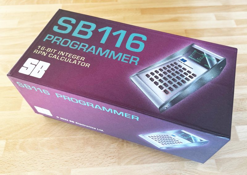
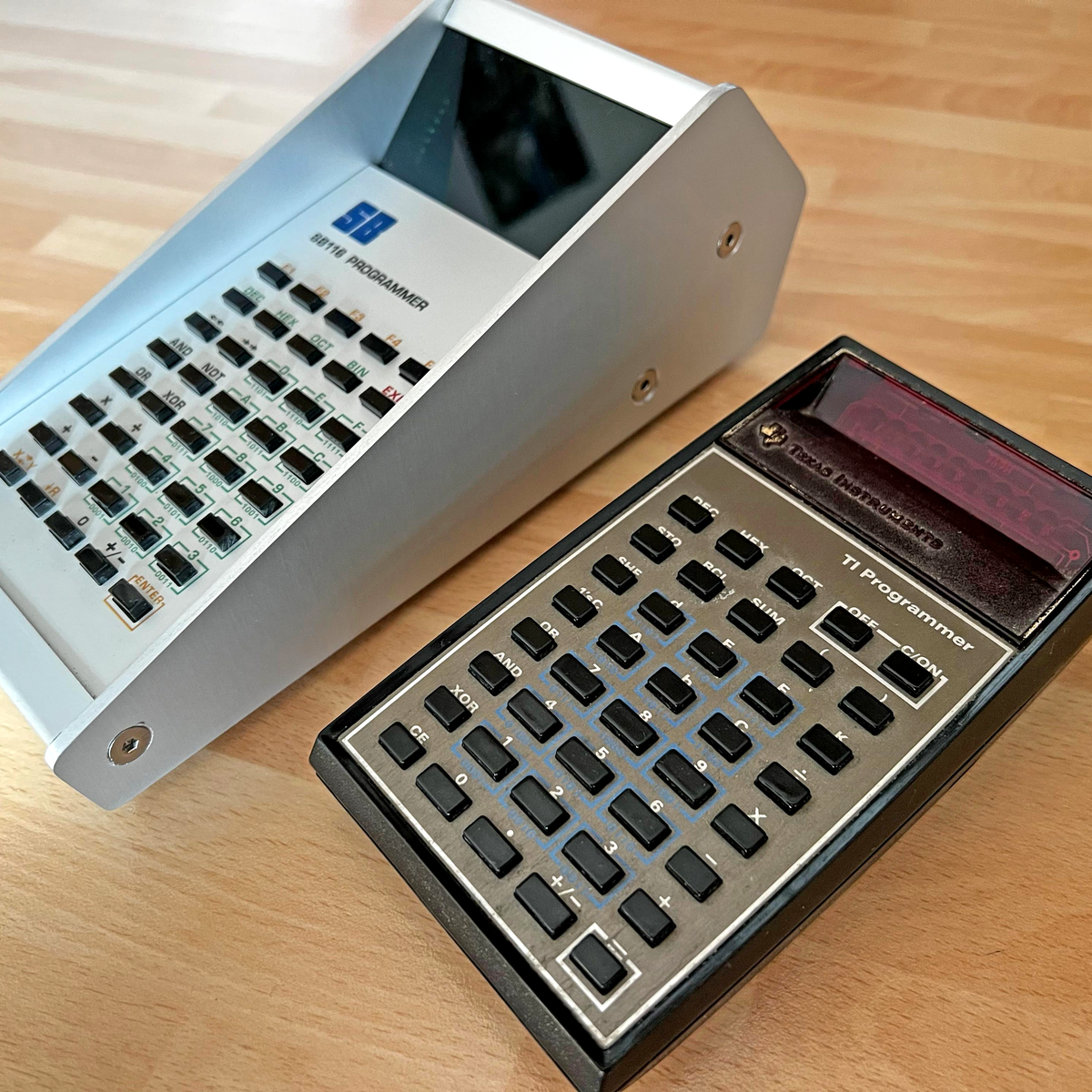
There’s something about Reverse Polish Notation (RPN) and the calculators that use it. It calls to mind a time when a calculator was a serious tool, and not just a throwaway toy. Created in the legacy of such calculators by HP and Texas Instruments, [Simon Boak] shows off his SB116, sporting an Arduino Nano under the hood. It’s a fully custom design, with a hand-built metal case, a custom PCB for the keyboard, and a tiny OLED display for maximum retro green goodness.
The impetus for this build was to replace a particular calculator, a well-used TI Programmer, that’s useful for working with 6502 assembly. The SB116 supports binary, octal, decimal, and hex; and boasts some downright useful functions — AND, NOT, OR, XOR, and bitshifts. The source code is available, but you’re on your own for the case and keyboard. And for maximized retro faux-nostalgia, [Simon] designed a box that would have looked right at home on an 80s store shelf.
Good news out of Mars from the little lunchbox that could — in the seven times that MOXIE has run since it arrived in February 2021, it has reached its target production of six grams of oxygen per hour, which is in line with the output of a modest tree here on Earth. The research team which includes MOXIE engineers report that although the solid oxide electrolysis machine has shown it can produce oxygen at almost any time or day of the Martian scale, they have not shown what MOXIE can do at dawn or dusk, when the temperature changes are substantial, but they say they have ‘an ace up (their) sleeve’ that will let them do that. We can’t wait to see what they mean.
In other, somewhat funnier space news — early last Sunday morning, the ESA’s Solar Orbiter was cruising by Venus as part of a gravity-assist maneuver to get the Orbiter closer to the Sun. Two days before the Orbiter was to reach its closest point to the spacious star, it spat a coronal mass ejection in the general direction of both Venus and the Orbiter (dibs on that band name), as if to say ‘boo’. Fortunately, the spacecraft is designed to withstand such slights, but the same cannot be said for Venus — these events have their way with Venus’ atmosphere, depleting it of gasses.
Is this not the most Hackaday-esque thing you’ve ever heard of? A solar-powered, Arduino-driven cockroach. Not a robot, an actual cockroach with a backpack. Why? Cyborg insects for urban search and rescue missions, obviously. We’d make some quip like ‘all it needs is a Nixie tube’, but in all seriousness, that would just weigh them down needlessly.
So anyway, here’s (an ‘Arduino guitar device’ playing) Wonderwall.
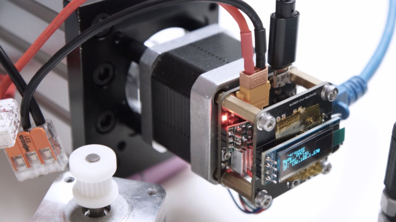
[Neumi] over on Hackaday.IO wanted a simple-to-use way to drive stepper motors, which could be quickly deployed in a wide variety of applications yet to be determined. The solution is named Ethersweep, and is a small PCB stack that sits on the rear of the common NEMA17-format stepper motor. The only physical connectivity, beside the motor, are ethernet and a power supply via the user friendly XT30 connector. The system can be closed loop, with both an end-stop input as well as an on-board AMS AS5600 magnetic rotary encoder (which senses the rotating magnetic field on the rear side of the motor assembly – clever!) giving the necessary feedback. Leveraging the Trinamic TMC2208 stepper motor driver gives Ethersweep silky smooth and quiet motor control, which could be very important for some applications. A rear-facing OLED display shows some useful debug information as well as the all important IP address that was assigned to the unit.
Control is performed with the ubiquitous ATMega328 microcontroller, with the Arduino software stack deployed, making uploading firmware a breeze. To that end, a USB port is also provided, hooked up to the uC with the cheap CP2102 USB bridge chip as per most Arduino-like designs. The thing that makes this build a little unusual is the ethernet port. The hardware side of things is taken care of with the Wiznet WS500 ethernet chip, which implements the MAC and PHY in a single device, needing only a few passives and a magjack to operate. The chip also handles the whole TCP/IP stack internally, so only needs an external SPI interface to talk to the host device.
Talking about firmware for a moment, to ease deployment, the network configuration is handled by DHCP, although some control over MAC address assignment is promised for the future. All control is via UDP over ethernet, and again the basic functionality is there, but some niceties such as motor synchronisation and state querying are again subject to further releases. Hardware design is implemented in KiCAD and FreeCAD, with Arduino covering the firmware and host control side in python. You can read all about it on the Ethersweep project GitHub, what is there not to like?
If you thought you’d seen this stepper-mounted driver setup before, you’d be correct, here’s a Hackaday Prize 2017 Entry for a CANBUS controlled driver. We also saw this on Dummy: the obscenely well made robot arm by [Zhihui Jun], which if you missed it, then do circle back and take a look, you won’t regret it!
Historically, there have been a few cases of useful wireless power transmission over great distances, like a team at MIT that was able to light up a 60 W bulb at several meters, and of course Nikola Tesla had grand dreams of drawing energy from the atmosphere. But for most of us wireless power is limited to small, short-range devices like cellphone chargers. While it’s not a lot of work to plug in a phone when it needs a charge, even this small task can be automated.
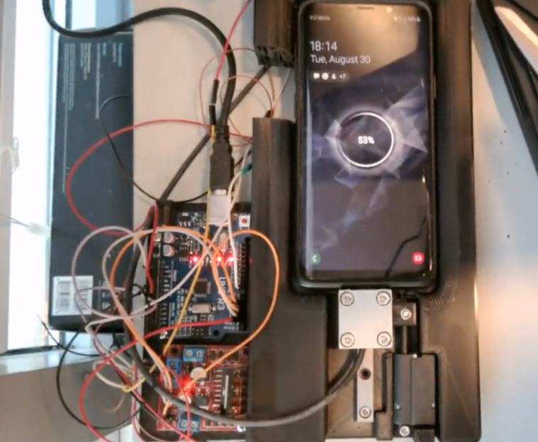
This build begins with a 3D printed cradle for the smartphone to sit in. When the device detects that the phone has been placed in the cradle, it uses a linear actuator to drive a custom-built charging cable into the phone’s USB port. Similarly, when the phone is lifted from the cradle the cable is automatically removed. It appears that there is some play in the phone’s position that lets the charger be plugged in smoothly, and the project’s creator [Larpushka] points out that the linear actuator is not particularly strong so we don’t imagine the risk of damage is very high.
While wireless charging still may have the edge when it comes to keeping debris out of the port, we still really enjoy a project like this that seems to be done for its own sake. There are some improvements that [Larpushka] plans to make, but for now we’re delighted by this build. For anyone looking to add true wireless charging to any phone that doesn’t have it, though, it’s not too difficult to accomplish either.
There are certain design aesthetics from every era that manage to survive the fads of their time and live throughout history. Ancient Greek architecture is still drawn upon for design inspiration in modern buildings, the mid-century modern style from the 60s still inspires various designs of consumer goods, and the rounded, clean looking cars from the 90s are still highly desirable qualities in automotive design. For electronics, though, we like this 70s-inspired calculator that [Aaron] recently built.
The calculator hearkens back to the days of calculators like the HP-29C with its large buttons and dot-matrix display. [Aaron] built the case out of various woods with a screen angled towards the user, and it uses a LCD display similar to those found in antique calculators. The brain of the calculator is an Arduino which fits easily into the case, and [Aaron] also built the keyboard from scratch with Cherry MX-style mechanical keys soldered together into a custom shape.
The software to run the calculator is fairly straightforward, but we are most impressed with the woodworking, styling, and keyboard design in this build. [Aaron] is also still ironing out some bugs with the power supply as it uses a DC-DC converter to power the device from a single lithium battery. For those who are more fond of early 2000s graphing calculators instead, be sure to take a look at this graphing calculator arcade cabinet.
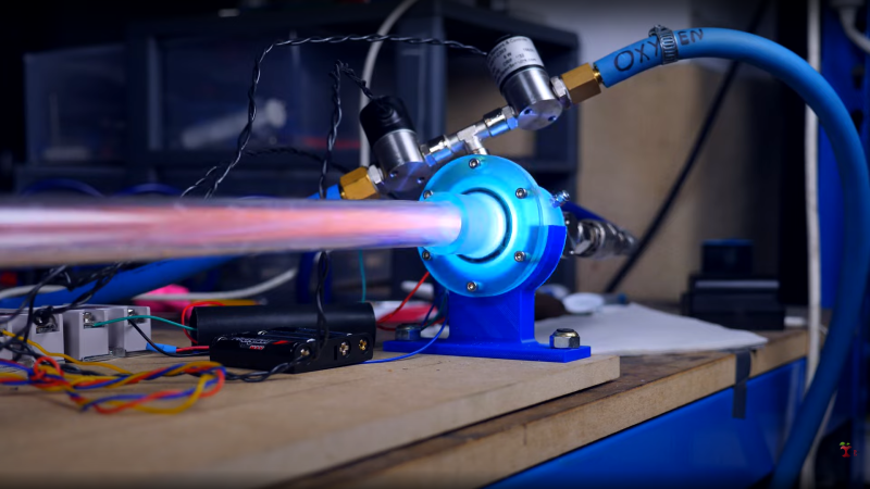
Over the years [Integza] has blown up or melted many types of jet engine, including the humble pulsejet. Earlier improvements revolved around pumping in more fuel, or forced air intakes, but now it’s time for a bit more refinement of the idea, and he takes a sidestep towards the more controllable detonation engine. His latest experiment (video, embedded below) attempts to dial-in the concept a little more. First he built a prototype from a set of resin printed parts, with associated tubing and gas control valves, and a long acrylic tube to send the exhaust down. Control of the butane and air injection, as well as triggering of the spark-ignition, are handled by an Arduino — although he could have just used a 555 timer — driving a few solid state relays. This provided some repeatable control of the pulse rate. This is a journey towards a very interesting engine design, known as the rotating detonation engine. This will be very interesting to see, if he can get it to work.
Supersonic exhaust plume with the characteristic ‘mushroom’ shape
Detonation engines operate due to the pressure part of the general thrust equation, where the action is in the detonative combustion. Detonative combustion takes place at constant pressure, which theoretically should lead to a greater efficiency than boring old deflagration, but the risks are somewhat higher. Apparently this is tricky to achieve with a fuel/air mix, as there just isn’t oomph in the mixture. [Integza] did try adding a Shchelkin spiral (we call them springs around here) which acts to slow down the combustion and shorten the time taken for it to transition from deflagration to detonation.
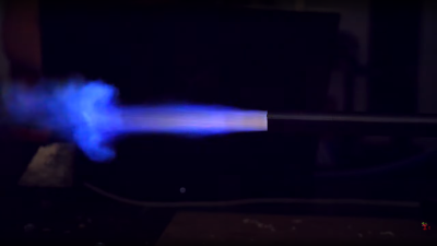
It sort of worked, but not well enough, so running with butane and pure oxygen was the way forward. This proved the basic idea worked, and the final step was to rebuild the whole thing in metal, with CNC machined end plates and some box section clamped with a few bolts. This appeared to work reasonably well at around 10 pulses/sec with some measurable thrust, but not a lot. More work to be done we think.
We hinted at earlier work on forced-air pulsejets, so here that is. Of course, whilst we’re on the subject of pulsejets, we can’t not mention [Colinfurze] and his pulsejet go kart.
Typewriters may be long past their heyday, but just because PCs, word processor software, and cheap printers have made them largely obsolete doesn’t mean the world is better off without them. Using a typewriter is a rich sensory experience, from the feel of the keys under your fingers that even the clickiest of PC keyboards can’t compare with, to the weirdly universal sound of the type hitting paper.
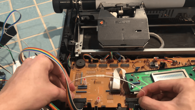
So if life hands you a typewriter, why not put it back to work? That’s exactly what [Artillect] did by converting an 80s typewriter into a Linux terminal. The typewriter is a Brother AX-25, one of those electronic typewriters that predated word processing software and had a daisy wheel printhead, a small LCD display, and a whopping 8k of memory for editing documents. [Artillect] started his build by figuring out which keys mapped to which characters in the typewriter’s 8×11 matrix, and then turning an Arduino and two multiplexers loose on the driving the print head. The typewriter’s keyboard is yet used for input, as the project is still very much in the prototyping phase, so a Raspberry Pi acts as a serial monitor between the typewriter and a laptop. The video below has a good overview of the wiring and the software, and shows the typewriter banging out Linux command line output.
For now, [Artillect]’s typewriter acts basically like an old-school teletype. There’s plenty of room to take this further; we’d love to see this turned into a cyberdeck complete with a built-in printer, for instance. But even just as a proof of concept, this is pretty great, and you can be sure we’ll be trolling the thrift stores and yard sales looking for old typewriters.
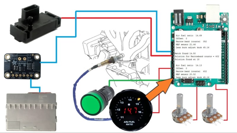
When [Robot Cantina] isn’t busy tweaking the 420cc Big Block engine in their Honda Insight, they’re probably working on some other completely far out automotive atrocity. In the video below the break, you’ll see them take the concept of a ‘lean burn’ system from the Insight and grafthack it into their 1997 Saturn coupe.
What’s a lean burn system? Simply put, it tricks the car into burning less fuel when it’s cruising under a light load to improve the vehicle’s average mileage. The Saturn’s electronics aren’t sophisticated enough to implement a lean burn system simply, and so [Robot Cantina] did what any of us might have done: hacked it in with an Arduino.
The video does a wonderful job going into the details, but essentially by using an oxygen sensor with finer resolution (wide-band) and then outputting the appropriate narrow band signal to the ECU, [Robot Cantina] can fine tune the air/fuel ratio with nothing more than a potentiometer, and the car’s ECU is none the wiser. What were the results? Well… they weren’t as expected, which means more experimentation, more parts, and hopefully, more videos. We love seeing the scientific method put to fun use!


 making uploading firmware a breeze. To that end, a USB port is also provided, hooked up to the uC with the cheap CP2102 USB bridge chip as per most Arduino-like designs. The thing that makes this build a little unusual is the ethernet port. The hardware side of things is taken care of with the