All of the tools you need to work with the FPGA Arduino — the Vidor — are now in the wild!
We reported earlier that a series of French blog posts finally showed how all the pieces fit together to program the FPGA on the Arduino MKR4000 Vidor board. Of course, I wasn’t content to just read the Google translation, I had to break out the board and try myself.
I created a very simple starter template, a tool in C to do the bitstream conversion, required, and bundled it all together in one place. Here’s how you can use my starter kit to do your own FPGA designs using the Vidor. I’m going to assume you know about FPGA basics and Verilog. If you don’t, why not check out the FPGA boot camps first?
The first thing you’ll want to do is grab my GitHub repo. You’ll also need the Arduino IDE (a recent copy) and Intel’s Quartus software. Inside, you’ll find three directories, two of which contain slightly modified copies of original Arduino files. But before you start digging in, let’s get the high-level overview of the process.
Basic Concepts
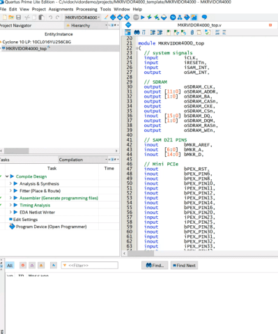 The FPGA onboard the Vidor is an Intel/Altera device so to configure it, we’ll use Quartus. Usually, Quartus handles everything including programming the device, but we can’t use it for that with the Vidor. Instead, we will have to tell the CPU how we want the FPGA configured and it will do it for us as part of our Arduino program (I really hate saying sketch).
Quartus (see below) will take our Verilog files and create a ttf file that represents the configuration bitstream. This is just an ASCII text file full of decimal numbers. Unfortunately, the way the Vidor is set up, it needs the numbers bit reversed at the byte level. That is, 01 in the ttf file needs to be 80 hex sent to the FPGA.
Arduino supplies a Java class file to do the task, but I got frustrated because the class file needed Java 11 and I didn’t want to put it on every machine I use, so I just rewrote it in C. It is easy enough to port the algorithm, though. In the shell subdirectory, I have another example implementation using awk.
Once you have this stream of numbers, you can include it in an Arduino sketch with some boilerplate to enable the FPGA and load it. The standard program includes the file app.h which is just the output of the conversion program. There’s no C code in it, just comma-separated numbers that the main code will stick in an array at compile-time. Beyond that, it is a normal Arduino program and you can do what you like. Upload it and you’ll get the CPU and FPGA programmed all in one go.
There is one caveat. The FPGA code has a top-level block with lots of I/O pins defined and the corresponding constraints. You should be very careful not to change these or alter the pin constraints. If you drive a pin that’s already an output, for example, you could do real harm to the board. Because all the pins are shared, you have the same problem with the Arduino pins, too. If you are driving an output pin with the FPGA, you shouldn’t try to drive it with the CPU also. However, as you will see, it is perfectly fine to have the FPGA reading a pin from the CPU or vice versa. That’s good because it gives us a way to send data back and forth between them.
On to Code
I wanted something simple, and I didn’t want to accidentally modify the Arduino boilerplate Verilog. You could instantiate a Verilog module, but this would require passing all the I/O pins into the module or modifying the original code every time, both of which I wanted to avoid.
My answer was to use the Verilog `include directive inside the boilerplate. That way your code has access to everything the main module has, but you don’t have to change the main module. The only downside is that Quartus has a smart compile feature that can’t figure out when only an include file changes. So it wasn’t recompiling when I made changes. I turned that feature off in the Quartus options, so if you pick up my example project, you won’t have any problems.
Here’s my example user.v:
reg [27:0] hadcounter;
assign bMKR_D[6]=bMKR_D[5]?hadcounter[27]:hadcounter[21];

always @(posedge wOSC_CLK)
begin
   if (!rRESETCNT[5])
   begin
      hadcounter<=28'hfffffff;
   end
   else
   begin
      if (hadcounter==28'h0) hadcounter<=28'hffffffff; else hadcounter<=hadcounter-28'h1;
   end
end
In the real file, I left a lot of comments in that explains what all the main module has that you can use. But the above is the working part. I define a 28 bit counter. The bMKR_D array is the digital ports for the Arduino and I’m using pin 6 and 5 as an output and an input, respectively.
The assign statement says, in English, If D5 is high, connect the 27th bit of the counter to the LED. If it is low, connect the 21st bit. The rest of the code just makes the counter countdown. I reload the counter even though it would naturally roll over in case you want to fine tune it to a different frequency.
As the counter runs, bit 27 will toggle relatively slowly, but bit 21 will be a good bit faster — that’s just how a counter is. So by changing D5 you can make the LED blink slow or fast.
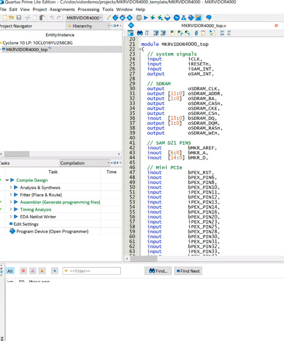
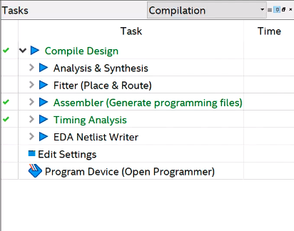
 As Verilog goes, this isn’t very complicated or even useful, but it is simple and shows that we can share data with the CPU in both directions. If you open the example project in Quartus, all you really need to do is make any changes to user.v you like, add any other files you want to use and double-click the Compile Design task (see left). If you get a successful compile, you’ll find the ttf file in the output_files directory. That’s the file you need to process with either the Java program, the C program, or the awk script. Either way, collect the output as app.h and put it in the same directory as your Arduino code.
CPU Side
On the sketch side, you need to leave the template code alone since it turns on the FPGA clock, among other things. You’ll notice it also includes app.h and uses a file called jtag.c to communicate with the FPGA. I didn’t segregate the Arduino code into its own include because you probably have to change the setup function, and make changes in global space, but that could be arranged (perhaps make setup call cpu_setup and loop call cpu_loop or something).
If you want to remove the demo parts of the blink-sketch file, you can get rid of:
- The definitions and calls related to FPGAVal, SPEED, and FPGALED
- The Serial calls and definitions
- Everything in the loop function
I left the unmodified code in the EmptySketch directory. Note in the demo code, though that SPEED is an output. This is set to D5, which is an input to the FPGA. By the same token, FPGALED corresponds to D6 and allows the CPU to read the state of the LED output.
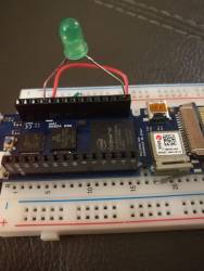
You will need an LED and dropping resistor on pin 6 unless you want to watch with a scope or a meter. I always keep some LEDs with built-in 5V dropping resistors handy, and even at 3.3V it was plenty bright. With one of those, you can just stick the wires right into the header socket on the board. Don’t try that with a regular LED, though!
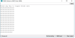
Once you run the sketch, you can open the serial monitor or any terminal at 9600 baud. There will be a message saying you can press any key to change the blink rate. Of course, since the serial monitor doesn’t allow you to press keys exactly, you’ll have to enter something and hit enter (set “No line ending” at the bottom of the monitor screen), but on a real terminal, any character press should do it.
The main code is pretty simple:
void loop() {
static int oldstate=-1;
static int linect=0;
int state;
if (Serial.read()!=-1)
  {
  FPGAVal=FPGAVal==HIGH?LOW:HIGH;
  digitalWrite(SPEED,FPGAVal);
  }
state=digitalRead(FPGALED);
if (state!=oldstate)
  {
  Serial.print(state);
  if (++linect==16)
    {
    Serial.println();
    linect=0;
    }
  oldstate=state;
  }
}
In the loop, if serial data appears, we just toggle the output going to the FPGA. We also sample the LED output on every pass. If it has changed from the last time, we write the new state to the terminal and then update the state so we don’t flood the screen with repeated characters. A lot of the code is just tracking when we’ve written enough to start a new line.
Vidor’s Hello World
I wanted to get everything you needed in one place and an example that would be easy to follow yet show the critical working parts. It would be easy enough to use the shared I/O pins to do SPI, for example, and then you could trade data with the FPGA quite easily. Don’t forget there’s Arduino IP (intellectual property; sort of library subroutines for FPGAs) in the IP directory, too, if you want to use it.
Now you just need a project idea that makes sense for an FPGA. Our personal favorite would be a logic analyzer. The CPU can talk to the PC, set up triggers and then let the FPGA do the dirty work of finding the trigger and storing data as fast as possible. If you want something less ambitious, it is very simple to create totally autonomous PWM outputs on an FPGA. We could see this being handy for robotics or machine control where you want a very rapid sequence of outputs without CPU intervention or overhead.
Of course, not every project has to make sense. If you are just wanting to learn about FPGAs there are plenty of projects you could do with a CPU but are easy enough to build in an FPGA (the classic traffic light comes to mind). Of course, with the Vidor you have an opportunity to use a blend of FPGA code and CPU code, which is kind of the point.


 [Ben Kolin] and his daughter [Alyssa] have come up with a clever hack that allows retrofitting existing hybrid vehicles with an extremely easy to understand indicator of real-time vehicle efficiency. No confusing graphics or arcade-style bleeps and bloops, just a color-changing orb which lives in the cup holder. An evolved version which takes the form of a smaller “dome light” that sits on the top of the dashboard could be a compelling aftermarket accessory for the hybrid market.