Posts with «arduino» label

Dual Arduino “CNC” control
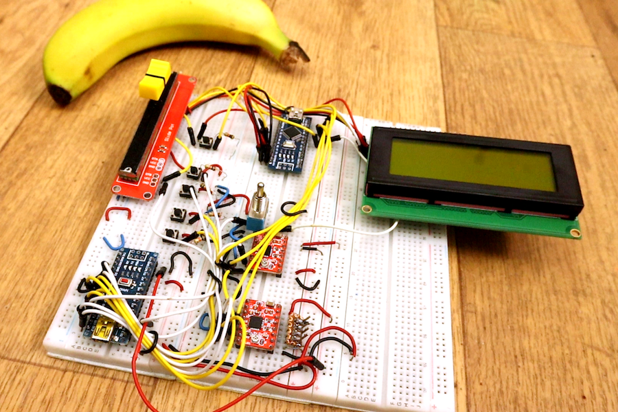
Generally when you work with CNC machinery, you program it on a computer, then allow a controller to automatically run through a cutting routine. Arduino boards have long been used for this kind of control through the grbl software package, but YouTuber Electronoobs decided to do things a bit differently.

His setup takes input from a potentiometer and several buttons, enabling manual control of his stepper motor-driven router. An Arduino Nano powers the motors through a pair of stepper drivers, while a second Nano is then used to output distance information on an LCD screen, letting him view exactly where his cutter is at a glance.

Why use 2 Arduinos? Well, if I use only one, the code would be very difficult with too much interruptions. We have to create pulses for the motors and print on the LCD at the same time. I’ve done that and each time I was printing on the LCD, there was a small pause in the motor rotation, and if the refresh rate is fast, the motors will have a pause each time and we don’t want that. That’s why I use 2 Arduinos. One will create the pulses for the motors and the other one will count the steps and print the distance and speed.

We have 2 step motors. I’ve used NEMA 17. Each with a A4988 driver. This driver needs 3 signals from the Arduino. Enable, direction and steps. The enable pin is connected to a toggle switch so we could start to stop the motors manually. The toggle switch is also connected to the Arduinos so we could know when the motors are enabled or not. To control speed we use a lineal potentiometer and to move axis and reset position, some push buttons with pulldowns. To print the distance, I’ve used an I2S LCD screen of 20×4 but you will have the code for the 16×2 version of LCD as well.

Besides adding a nice readout to the machine, this concept could certainly form the basis for all manner of other stepper-driven devices.

Arduino Gets a Command Line Interface

When using an Arduino, at least once you’ve made it past blinking LEDs, you might start making use of the serial connection to send and receive information from the microcontroller. Communicating with the board while it’s interacting with its environment is a crucial way to get information in real-time. Usually, that’s as far as it goes, but [Pieter] wanted to take it a step farther than that with his command line interpreter (CLI) for the Arduino.

The CLI allows the user to run Unix-like commands directly on the Arduino. This means control of GPIO and the rest of the features of the microcontroller via command line. The CLI communicates between the microcontroller and the ANSI/VT100 terminal emulator of your choosing on your computer, enabling a wealth of new methods of interacting with an Arduino.

The CLI requires a hex file to be loaded onto the Arduino that you can find at a separate site, also maintained by [Pieter]. Once that’s running, you can get all of that sweet command line goodness out of your Arduino. [Pieter] also has some examples on his project page, as well as the complete how-to to get this all set up and running. There’s a lot going on in the command line world, in Linux as well as windows. So there’s plenty to explore there as well.

Hack a Day 11 Nov 03:00
arduino  cli  command line  gpio  i2c  microcontrollers  serial  shell  unix  uno  

Digital Rain Cloud


Description

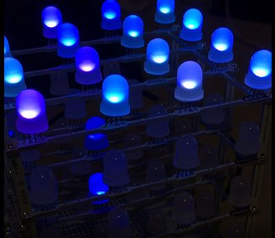
This is a very simple project that turns a Rainbow Cube Kit from Seeedstudio, into a digital rain cloud. It features a relaxing rain animation which is ruined by a not-so-relaxing yet somewhat realistic lightning effect. The animation has a very random pattern, and is quite satisfying to watch. The strategically placed cotton wool on the top of the cube makes all the difference to the project, and is sure to impress all of your friends. Luckily, I have done all of the hard work for you. You will find the full source code for the animation sequence below. You just have to provide the Rainbow Cube Kit and the cotton wool. Have fun !!


Debugging Arduino is Painful: This Can Help

If you are used to coding with almost any modern tool except the Arduino IDE, you are probably accustomed to having on-chip debugging. Sometimes having that visibility inside the code makes all the difference for squashing bugs. But for the Arduino, most of us resort to just printing print statements in our code to observe behavior. When the code works, we take the print statements out. [JoaoLopesF] wanted something better. So he created an Arduino library and a desktop application that lets you have a little better window into your program’s execution.

To be honest, it isn’t really a debugger in the way you normally think of it. But it does offer several nice features. The most rudimentary is to provide levels of messaging so you can filter out messages you don’t care about. This is sort of like a server’s log severity system. Some messages are warnings and some are informational, and some are verbose. You can select what messages to see.

In addition, the library timestamps the messages so you can tell how much time elapsed between messages and what function you were in during the message. It can also examine and set global variables that you preconfigure and set watches on variables. It is also possible to call functions from the serial monitor.

There’s a companion Java program (see video below) although you can use most of the features directly from the normal serial monitor, it just isn’t as pretty. The Java program can also read an Arduino program file and convert all the print calls in it to use the library, if you like.

As you might expect, this requires some cooperation from your program. You have to set up the library and the serial port. You also have to arrange for the main function to run frequently (for example, in the main loop). By default, the debugging is mostly suppressed (although you can change that). You have to issue a serial port command to turn on higher level logging and debug functions.

If you start with the examples that come with the library (use the simple one for an AVR-based Arduino and the advanced one for any others), you’ll see a few #defines you can use to control the library:

  • DEBUG_DISABLED – Set to true and the library compiles out with no overhead
  • DEBUG_DISABLE_DEBUGGER – Turn off everything but message logging
  • DEBUG_INITIAL_LEVEL – Starting level of debug messages
  • DEBUG_USE_FLASH_F – Store debug messages in flash memory

There’s really two versions of the code: one for 8-bit AVR processors and another for other Arduino types. We found problems building both of them. The files src/utility/Fields.cpp, src/utility/Vector.h, and
src/utility/Util.cpp refer to arduino.h. That works on computers that have case-insensitive file systems. In each case, for Linux, it needs to be Arduino.h. In addition, SerialDebug.cpp is lacking a stdarg.h include. We’ve reported both of these issues to the developer so they may be fixed by now.

You can explore the video and the documentation to see how it all works. Is it a full-blown debugger? No. You can’t stop execution (odd, because you certainly could technically), set breakpoints, or single step. But it still useful to have access to at least some of your program’s internal state.

Of course, Arduino has promised full debugging soon. We’ve even seen one Arduino debugging another via debugWIRE.

Hack a Day 08 Nov 06:00

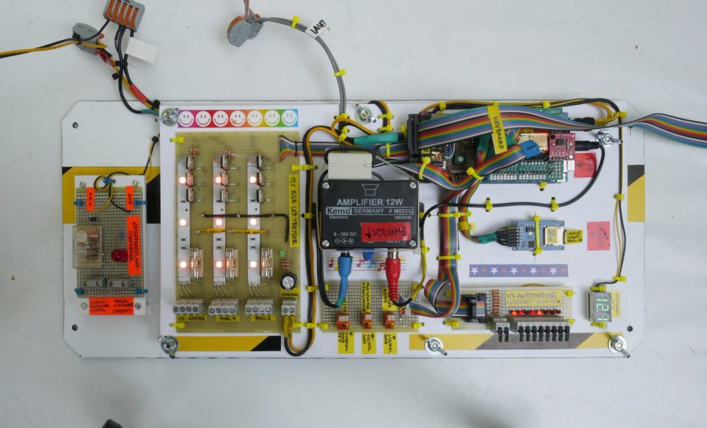
Arduino Mega controls this amazing water organ

Earlier this year, artist Niklas Roy was invited to participate in the Drehmoment art festival that takes place in the south-west of Germany. The “catch” to this festival is that each artist was invited to team up with a local company to take advantage of their products and resources. Of these was cleaning equipment brand Kärcher, known for their pressure washers.

With this company’s backing, Roy put together a musical water fountain powered by eight pressure washers, dubbing it the “Wasserorgel von Winnenden,” or “Water Organ of Winnenden”—the location of Kärcher’s headquarters. 

The installation is controlled by an Arduino Mega, along with supporting electronics including a Music Maker Shield and solid state relays to activate the pressure washers. During the festival, passerby were invited play some tunes using a 3D-printed keyboard made to withstand the elements and less-than-gentle interactions.

The brain of the Wasserorgel was an Arduino MEGA 2560, stacked with an Adafruit Music Maker Shield. The MIDI synthesizer of the shield generated the instrument sounds based on the input coming from a self-built, 3D-printed keyboard. The keyboard was designed solid enough to withstand weather and the misguided enthusiasm of drunk people at 3 ‘o clock at night. The program on the Arduino translated the keystrokes into water and light effects by switching 12V RGB LEDs via darlington transistors and the eight pressure sprayers via solid state relays. Five of the pressure sprayer fountains were installed on top of the main basin, one was installed on top of an existing fountain and two were installed on the roof of the Kronenplatz-building.

You can find more information in Roy’s project write-up, and see it in action below!

LED “Nixie” Display

Laser-cut and edge-lit, these 10-digit numeric displays are bigger, brighter, and safer than the old tubes.

Read more on MAKE

The post LED “Nixie” Display appeared first on Make: DIY Projects and Ideas for Makers.

Suspense Courtesy of Arduino, Mess of Wires

The ticking clock on the bomb is a Hollywood trope that simply refuses to die. Adding to the stress levels of the bomb squad and creating great suspense for the watcher, it’s always interesting to wonder why the average bomb maker is so courteous as to supply this information to law enforcement. Regardless, if you’d like to build a dramatic prop and are mature enough to do so responsibly, [Giorgio] has the guide you need.

The build is a straightforward one, relying on an Arduino to run the show. This is hooked up to a classic 7-segment LED display, upon which the countdown is displayed. For extra flair, an MP3 player is fitted to play the Mission Impossible theme. It all adds to the tension as you wipe the sweat from your brow, trying to decide if you’re cutting the right wire.

It’s a build that would be an excellent prop for a film production or a fun game at a holiday party. However, it’s also a build that could easily be mistaken for the real thing by those less technically inclined. Even the most innocuous homebrew projects have caused problems for innocent hackers in the past. Fake bombs can be incredibly dangerous, just like the real thing, so it’s important to be careful.

We’ve seen other takes on this kind of build before, too. As always, build responsibly.

Hack a Day 07 Nov 03:00

Vintage-style clock made from individual LEDs

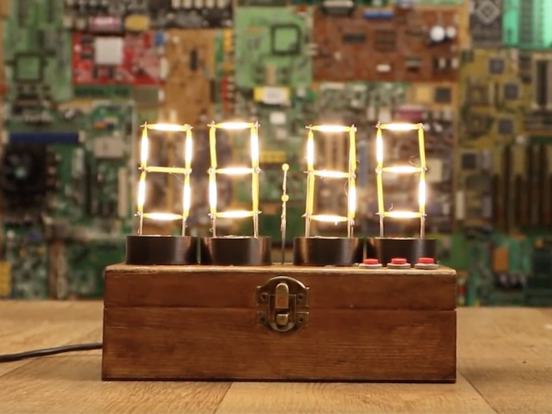
If you’ve ever wanted a vintage-style timepiece, or to test your soldering abilities, this clock by YouTuber Electronoobs will let you do both at once. 

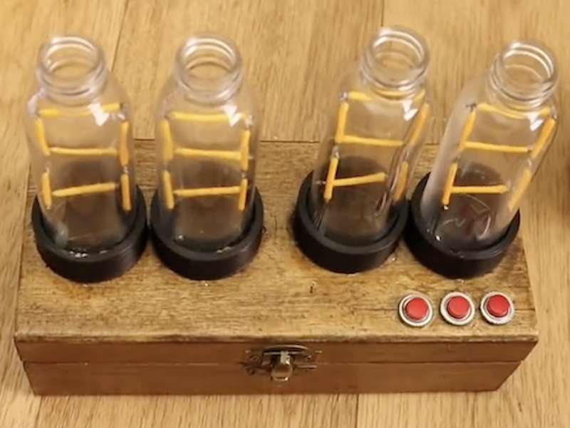
It features four display modules that resemble Nixie tubes, each made out of LED filaments soldered onto a steel wire frame. If you find soldering enjoyable and relaxing, this is likely a good project for you; though if not, there are of course other options. 

The device is controlled by an Arduino Nano, along with a MAX7219 display driver to power the LEDs as needed. An RTC module keeps things “ticking” at the correct pace, and a pair of buttons on top of the wooden enclose allow the time to be adjusted as needed.

I’ve made some “Nixie” tubes. These are actually 7-segment displays made with filament LEDs but placed in a plastic bottle so it will have a more vintage nixie look. To control the LEDs I’m using the MAX7219 driver that could control 4 x 7-segment displays. To get the real time, I’m using the DS3231 module that works with an I2C communication so it’s easy to use. The project also has 2 push buttons to set the hour and minute. All is inside a wood case painted with varnish so it will look more vintage.

Check it out in the video below, or see the build write-up for more info.

Weather Station Is A Tutorial in Low Power Design

Building your own weather station is a fun project in itself, but building it to be self-sufficient and off-grid adds another set of challenges to the mix. You’ll need a battery and a solar panel to power the station, which means adding at least a regulator and charge controller to your build. If the panel and battery are small, you’ll also need to make some power-saving tweaks to the code as well. (Google Translate from Italian) The tricks that [Danilo Larizza] uses in his build are useful for more than just weather stations though, they’ll be perfect for anyone trying to optimize their off-grid projects for battery and solar panel size.

When it comes to power conservation, the low-hanging fruit is plucked first. [Danilo] set the measurement intervals to as long as possible and put the microcontroller (a NodeMCU) to sleep in between. Removing the power from the sensors when the microcontroller was asleep was another easy step, but the device was still crashing overnight. Then he turned to a hardware solution and added a more efficient battery charger to the setup, which saved even more power. This is all the more impressive because the station communicates via WiFi which is notoriously difficult to run in low-power applications.

Besides the low power optimizations, the weather station itself is interesting for its relative simplicity. It could be built with things most of us have knocking around. Best of all, [Danilo] published the source code on his site, so most of the hard work has been done already. If you’re thinking he seems a little familiar, it’s because we’ve featured some of his projects before, like his cheap WiFi extender antenna and his homemade hybrid tube amplifier.

Gyro Controlled RGB Blinky Ball Will Light up Your Life

[James Bruton], from the XRobots YouTube channel is known for his multipart robot and cosplay builds. Occasionally, though, he creates a one-off build. Recently, he created a video showing how to build a LED ball that changes color depending on its movement.

The project is built around a series of 3D printed “arms” around a hollow core, each loaded with a strip of APA102 RGB LEDs. An Arduino Mega reads orientation data from an MPU6050 and changes the color of the LEDs based on that input. Two buttons attached to the Mega modify the way that the LEDs change color. The Mega, MPU6050, battery and power circuitry are mounted in the middle of the ball. The DotStar strips are stuck to the outside of the curved arms and the wiring goes from one end of the DotStar strip, up through the middle column of the ball to the top of the next arm. This means more complicated wiring but allows for easier programming of the LEDs.

Unlike [James’] other projects, this one is a quickie, but it works as a great introduction to programming DotStar LEDs with an Arduino, as well as using an accelerometer and gyro chip. The code and the CAD is up on Github if you want to create your own. [James] has had a few of his projects on the site before; check out his Open Dog project, but there’s also another blinky ball project as well.

Hack a Day 03 Nov 03:00