

Arduino Watchdog Has Bite And Doesn’t Need Treats
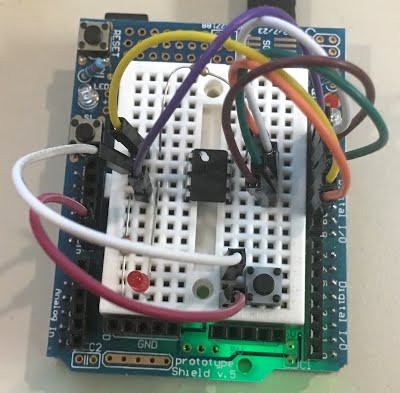
My dog Jasper isn’t much of a watchdog: he’s too interested in sleeping and chasing my cats to keep an eye on things. Fortunately, [Vadim] has come up with a more reliable alternative with this simple Arduino watchdog. It’s designed to work with crypto coin mining rigs, but it could be easily adapted for other high-uptime uses, such as file servers or doomsday weapons.
The way it works is simple: a small program on the watched computer sends a command over the serial port: a polite “hello”. The Arduino watchdog picks this up and responds with an equally polite “HELLO”. That starts the watchdog running. A simple Java program on the watched computer then sends a ping every five seconds over the serial port to let the watchdog know it is still running okay.

If the watchdog doesn’t receive this ping, it uses reed relay wired into the reset pins of the computer to trigger a reset. It then waits for the watched computer to say hello, starting the process again.
[Vadim] includes a demo video where the system resets an unreliable crypto mining rig. It does have limitations, of course: if the mining program crashes without taking down the entire computer, the watchdog won’t be triggered, and it won’t work if the problem requires a full hard power reset rather than a soft reset. dIt’s a neat little build that could be easily modified to handle all these issues, though, and you don’t need to keep feeding it treats to keep its attention, unlike Jasper.
 A delightful version of a clever one-dimensional game has been made by [Critters] which he calls