Macros are useful things. They allow one to execute a series of commands with a single keypress. There exists a wide variety of hardware and software solutions to create and use macros to improve your workflow, and now [Evan] has brought the open-source ManyKey into the fray, along with a build tutorial to boot.
The tutorial acts as a great introduction to ManyKey, as [Evan] walks through the construction of a macro keyboard designed to be operated by the feet. Based around the Arduino Leonardo and using off-the-shelf footswitches commonly used in guitar effects, it’s accessible while still hinting at the flexibility of the system. Macros are programmed into the keyboard through a Python app which communicates over serial, and configurations are saved into the Arduino’s onboard EEPROM. The ManyKey source is naturally available over at GitHub.
[Evan] tells us he uses his setup to run DJ software with his feet while his hands are busy on the turntables. That said, there’s all manner of other applications this could be used for. Efficiency is everything, and we love to see keyboard projects that aim to improve workflow with new ideas and custom builds – this shortcut keyboard makes a great example.
An Arduino and a data radio can make a great remote sensor node. Often in such situations, the hardware ends up installed somewhere hard to get to – be it in a light fitting, behind a wall, or secreted somewhere outdoors. Not places that you’d want to squeeze a cable repeatedly into while debugging.
Using the NRF24L01 chip with the Arduino is a popular choice to add wireless communications to a small project. By installing one of these radios on both the remote hardware and a local Arduino connected to the programming computer, it’s possible to remotely flash the Arduino without any physical contact whatsoever using Optiboot.
The writeup is comprehensive and covers both the required hardware setup for both ends of the operation as well as how to install the relevant bootloaders. If you’re already using the NRF24L01 in your projects, this could be the ideal solution to your programming woes. Perhaps you’re using a different platform though – like an Arduino on WiFi? Don’t worry – you can do OTA updates that way, too.
There are plenty of PC joysticks out there, but that didn’t stop [dizekat] from building his own. Most joysticks mechanically potentiometers or encoders to measure position. Only a few high-end models use Hall effect sensors. That’s the route [dizekat] took.
Hall effect sensors are non-contact devices which measure magnetic fields. They can be used to measure the position and orientation of a magnet. That’s exactly how [dizekat] is using a trio of sensors in his design. The core of the joystick is a universal joint from an old R/C car. The center section of the joint (called a spider) has two one millimeter thick disc magnets glued to it. The Hall sensors themselves are mounted in the universal itself. [Dizekat] used a small piece of a chopstick to hold the sensors in position while he found the zero point and glued them in. A third Hall effect sensor is used to measure a throttle stick positioned on the side of the box.
An Arduino micro reads the sensors and converts the analog signal to USB. The Arduino Joystick Library by [Matthew Heironimus] formats the data into something a PC can understand.
While this is definitely a rough work in progress, we’re excited by how much [dizekat] has accomplished with simple hand tools and glue. You don’t need a 3D printer, laser cutter, and a CNC to pull off an awesome hack!
At its heart is a modified Arduino Nano clone that draws a measured 608 nA from a CR2450N. From the specification of the cell he has calculated the 50 year maximum figure, as well as a possible 29 years for a CR2032 and 64 years for a CR2477. He does however note that this does not take self-discharge into account, but you can probably afford a new battery in a decade or so.
The Arduino clone carefully selected for its “P” version low-power processor has had its serial bridge IC removed to achieve this power consumption, as well as a voltage regulator and some discrete components. Interestingly he notes that the ATMega168P is even more frugal than its 328 cousin, so he’s used the former chip. A selection of internal flags are set for minimal power consumption, and the internal oscillator is selected to use as low a clock speed as possible. There is an Intersil ISL1208 low power RTC chip mounted on a piece of stripboard to provide the timing, and of course an LED to provide the essential birthday alert.
When the LED lights for the big day there’s always the hope you’ll receive another coin cell, this time powering an edge-lit musical birthday card.
In a project, repetitive tasks that break the flow of development work are incredibly tiresome and even simple automation can make a world of difference. [Simon Merrett] ran into exactly this while testing different stepper motors in a strain-wave gear project. The system that drives the motor accepts G-Code, but he got fed up with the overhead needed just to make a stepper rotate for a bit on demand. His solution? A grbl man-in-the-middle jog pendant that consists of not much more than a rotary encoder and an Arduino Nano. The unit dutifully passes through any commands received from a host controller, but if the encoder knob is turned it sends custom G-Code allowing [Simon] to dial in a bit acceleration-controlled motor rotation on demand. A brief demo video is below, which gives an idea of how much easier it is to focus on the nuts-and-bolts end of hardware when some simple motor movement is just a knob twist away.
[Simon]’s jog pendant moves a single motor which is exactly what he needs to ease development of his 3D printed strain-wave gear using a timing belt, but it could be programmed with any G-Code at all. Speaking of DIY jog pendants for CNC machines, don’t forget this wireless one made from an Atari 2600 joystick that jogs a plasma cutter in X and Y, and zeroes it with a push of the button.
What do you do, when you need a random number in your programming? The chances are that you reach for your environment’s function to do the job, usually something like rand() or similar. This returns the required number, and you go happily on your way.
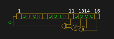
A shift register configured as a pseudo-random number generator. [by KCAuXy4p CC0 1.0]Except of course the reality isn’t quite that simple, and as many of you will know it all comes down to the level of randomness that you require. The simplest way to generate a random number in software is through a pseudo-random number generator, or PRNG. If you prefer to think in hardware terms, the most elementary PRNG is a shift register with a feedback loop from two of its cells through an XOR gate. While it provides a steady stream of bits it suffers from the fatal flaw that the stream is an endlessly repeating sequence rather than truly random. A PRNG is random enough to provide a level of chance in a computer game, but that predictability would make it entirely unsuitable to be used in cryptographic security for a financial transaction.
There is a handy way to deal with the PRNG predictability problem, and it lies in ensuring that its random number generation starts at a random point. Imagine the shift register in the previous paragraph being initialised with a random number rather than a string of zeros. This random point is referred to as the seed, and if a PRNG algorithm can be started with a seed derived from a truly unpredictable source, then its output becomes no longer predictable.
Selecting Unpredictable Seeds
Computer systems that use a PRNG will therefore often have some form of seed() function alongside their rand() function. Sometimes this will take a number as an argument allowing the user to provide their own random number, at other times they will take a random number from some source of their own. The Sinclair 8-bit home computers for example took their seed from a count of the number of TV frames since switch-on.
The not-very-random result of a thousand analogRead() calls.
The Arduino Uno has a random() function that returns a random number from a PRNG, and as you might expect it also has a randomSeed() function to ensure that the PRNG is seeded with something that will underpin its randomness. All well and good, you might think, but sadly the Atmel processor on which it depends has no hardware entropy source from which to derive that seed. The user is left to search for a random number of their own, and sadly as we were alerted by a Twitter conversation between @scanlime and @cybergibbons, this is the point at which matters start to go awry. The documentation for randomSeed() suggests reading the random noise on an unused pin via analogRead(), and using that figure does not return anything like the required level of entropy. A very quick test using the Arduino Graph example yields a stream of readings from a pin, and aggregating several thousand of them into a spreadsheet shows an extremely narrow distribution. Clearly a better source is called for.
Noisy Hardware or a Jittery Clock
As a slightly old-school electronic engineer, my thoughts turn straight to a piece of hardware. Source a nice and noisy germanium diode, give it a couple of op-amps to amplify and filter the noise before feeding it to that Arduino pin. Maybe you were thinking about radioactive decay and Geiger counters at that point, or even bouncing balls. Unfortunately though, even if they scratch the urge to make an interesting piece of engineering, these pieces of hardware run the risk of becoming overcomplex and perhaps a bit messy.
The significantly more random result of a thousand Arduino Entropy Library calls.
The best of the suggestions in the Twitter thread brings us to the Arduino Entropy Library, which uses jitter in the microcontroller clock to generate truly random numbers that can be used as seeds. Lifting code from the library’s random number example gave us a continuous stream of numbers, and taking a thousand of them for the same spreadsheet treatment shows a much more even distribution. The library performs as it should, though it should be noted that it’s not a particularly fast way to generate a random number.
So should you ever need a truly random number in your Arduino sketch rather than one that appears random enough for some purposes, you now know that you can safely disregard the documentation for a random seed and use the entropy library instead. Of course this comes at the expense of adding an extra library to the overhead of your sketch, but if space is at a premium you still have the option of some form of hardware noise generator. Meanwhile perhaps it is time for the Arduino folks to re-appraise their documentation.
There’s something about impressing strangers on the Internet that brings out the best in us. Honestly, we wouldn’t be able to run this site otherwise. A perfect example of this phenomenon is the annual Reddit Secret Santa, where users are challenged to come up with thoughtful gifts for somebody they’ve never even met before.
Hardware packed into the lid so the box itself remains empty.
There’s quite a bit of hardware hidden under the hood of this bedazzled gift box. The primary functions of the box are handled by an Arduino Nano; which runs the trivia game and provides user interaction via a 16×2 LCD, three push buttons, and a buzzer. Once the trivia game is complete, a servo is used to unlock the box and allow the recipient access to the physical gifts.
But that’s not the only trick this box has hidden inside. Once the main trivia game is complete, a ESP8266 kicks into action and advertises an access point the user can connect to. This starts the second level of challenges and gifts, which includes a code breaking challenge and gifted software licenses.
The project wasn’t all smooth sailing though. [Harrison] admits that his skills are still developing, and there were a few lessons learned during this project he is unlikely to forget in the future. Some Magic Smoke managed to escape when he connected his 5V Arduino directly to the 3.3V ESP8266, but at least it was a fairly cheap mistake and he had spares on hand to get the project completed anyway.
If you’ve been hanging around microcontrollers and electronics for a while, you’re surely familiar with the concept of the breakout board. Instead of straining to connect wires and components to ever-shrinking ICs and MCUs, a breakout board makes it easier to interface with the device by essentially making it bigger. The Arduino itself, arguably, is a breakout board of sorts. It takes the ATmega chip, adds the hardware necessary to get it talking to a computer over USB, and brings all the GPIO pins out with easy to manage header pins.
But what if you wanted an even bigger breakout board for the ATmega? Something that really had some leg room. Well, say no more, as [Nick Poole] has you covered with his insane RedBoard Pro Micro-ATX. Combining an ATmega32u4 microcontroller with standard desktop PC hardware is just as ridiculous as you’d hope, but surprisingly does offer a couple tangible benefits.
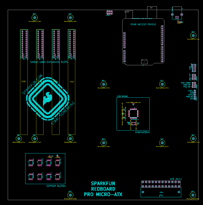
RedBoard PCB layout
The RedBoard is a fully compliant micro-ATX board, and will fit in pretty much any PC case you may have laying around in the junk pile. Everything from the stand-off placement to the alignment of the expansion card slots have been designed so it can drop right into the case of your choice.
That’s right, expansion slots. It’s not using PCI, but it does have a variation of the standard Arduino “shield” concept using 28 pin edge connectors. There’s a rear I/O panel with a USB port and ISP header, and you can even add water cooling if you really want (the board supports standard LGA 1151 socket cooling accessories).
While blowing an Arduino up to ATX size isn’t exactly practical, the RedBoard is not without legitimate advantages. Specifically, the vast amount of free space on the PCB allowed [Nick] to add 2Mbits of storage. There was even some consideration to making removable banks of “RAM” with EEPROM chips, but you’ve got to draw the line somewhere. The RedBoard also supports standard ATX power supplies, which will give you plenty of juice for add-on hardware that may be populating the expansion slots.
There’s a lot more to learning how to play the guitar than just playing the right notes at the right time and in the right order. To produce any sound at all requires learning how to do completely different things with your hands simultaneously, unless maybe you’re a direct descendant of Eddie Van Halen and thus born to do hammer ons. There’s a bunch of other stuff that comes with the territory, like stringing the thing, tuning it, and storing it properly, all of which can be frustrating and discouraging to new players. Add in the calluses, and it’s no wonder people like Guitar Hero so much.
In an interesting departure from standard stringed instrument construction, plucking is isolated from fretting. The player fingers notes on four strings but plucks a special, fifth string with a conductive pick that closes the plucking circuit. By contrast, the fretting strings are normally high. When pressed, they contact the foil-covered fingerboard and the circuit goes low. All five strings are made of carbon-impregnated elastic and wrapped with 30AWG copper wire.
All five strings connect to an Arduino UNO and then a laptop. The laptop sends the signal to a Bluefruit friend to change Bluetooth to UART in order to satisfy the PIC32. From there, it goes out via 2-channel DAC to a pair of PC speakers. One channel has the string tones, which are generated by Karplus-Strong. To fill out the sound, the other DAC channel carries undertones for each note, which are produced by sine tables and direct digital synthesis. There’s no cover charge; just click past the break to check it out.
A lot of the DIY laser engravers and cutters we cover here on Hackaday are made with laser diodes salvaged from Blu-ray drives and projectors, which are visible lasers in the 400 – 450nm range (appearing as violet or blue). Unfortunately there is an upper limit in terms of power on visible diode lasers, most builds max out at 5W or so. If you need more power than that, you’ll likely find yourself looking at gas laser cutters like the K40. While the K40 is a great starting point if you’re looking to get into “real” lasers, it’s a very different beast from the homebrew builds using visible lasers.
With a gas laser the beam itself is invisible, making it much more difficult to align or do test runs. One solution is to add a visible laser to the K40 which can be used to verify alignment, but making sure it’s traveling down the same path as the primary laser usually requires an expensive beam combiner. Looking to avoid this cost, [gafu] wanted to see if it was possible to simply move the visible laser into the path of the primary beam mechanically.
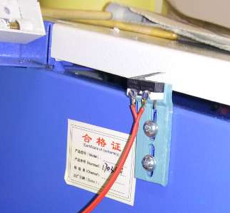
An adjustable microswitch detects when the lid has been opened.
In the setup that [gafu] has come up with, a cheap laser module (the type from a handheld laser pointer) is moved into the path of the primary laser on an arm that’s actuated by a simple hobby servo. To prevent the primary and visible lasers from firing at the same time, an Arduino is used to control the servo given the current state of the K40’s lid. If the lid of the K40 is open, the primary laser is shutoff and the visible laser is rotated into position so the operator can see where the primary laser’s beam would be hitting. Once the lid is closed, the visible laser rotates out of the way and the primary is powered back up.
Running the cutting or engraving job with the lid of the K40 machine open now let’s [gafu] watch a “dry run” of the entire operation with the visible laser before finally committing to blasting the target with the full power beam.


 In a project, repetitive tasks that break the flow of development work are incredibly tiresome and even simple automation can make a world of difference. [Simon Merrett] ran into exactly this while testing different stepper motors in a strain-wave gear project. The system that drives the motor accepts G-Code, but he got fed up with the overhead needed just to make a stepper rotate for a bit on demand. His solution? A


