Posts with «teensy» label

Teensy 3.5 & 3.6 Kickstarter

As many of the followers of my blog know, the Teensy 3.1 and Teensy LC have been my favorite microcontroller boards for the past couple of years.  The Teensy 3.1 has since been replaced by the slightly better Teensy 3.2, which has a better voltage regulator but is otherwise pretty much the same as the 3.1.  I’ve been using the Teensy LC with PteroDAQ software for my electronics course.

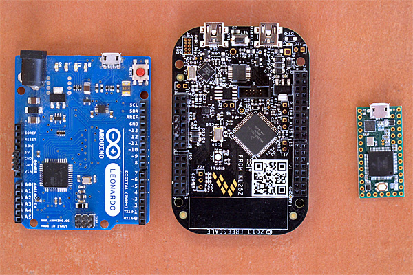
I’ve just noticed that PJRC has a Kickstarter campaign for a new set of boards the Teensy 3.5 and 3.6.  These will be much more powerful ARM processors (120MHz and 180MHz Cortex M4 processors with floating-point units, so at least 2.5 times faster than the Teensy 3.2, more if floating-point is used much).  The form factor is similar to before, but the boards are longer, taking up 24 rows of a breadboard, instead of just 14.  The extra board space is mainly to provide more I/O, but there is also a MicroSD card slot.

The designer is still dedicated to making the Teensy boards run in the Arduino environment, and the breadboard-friendly layout is very good for experimenting.

PJRC is positioning the new boards between the old Teensy boards and the Linux-based boards like the Raspberry Pi boards. The new Teensy boards will have a lot of raw power, but not an operating system, though I suspect that people outside PJRC will try porting one of the small real-time operating systems to the board.

The new boards are a bit pricey compared to the Teensy LC ($23–28 instead of under $12 for the Teensy LC), but still reasonable for what they provide.  PJRC also has a history of providing good software for their boards.

I probably need to get both a Teensy 3.5 and a 3.6 to port PteroDAQ to them—that looks like a $50 purchase. If the boards and the software are available in time for me do development on PteroDAQ by December, I might get it done—any later than that and I’ll have no time, as I have a very heavy teaching and service load for Winter quarter.

I suspect that the new Teensyduino software will need a newer version of the Arduino development environment, which in turn would require a newer version of the Mac operating system (my laptop is still running 10.6.8), which in turn probably means a new laptop.

I’m waiting to see if Apple releases a new, usable MacBook Pro in October, so there is a bit of built-in delay in the whole process. I’m not impressed with their recent design choices for iPhones and MacBook Air—I need connections to my laptop—so there is a strong possibility that I may be having to leave the Macintosh family of products after having been a loyal user since 1984 (that’s 32 years now).


Filed under: Uncategorized Tagged: Arduino, Kickstarter, PteroDAQ, Teensy

DIY Motion Control Camera Rig Produces Money-Shots On A Budget

Motion control photography allows for stunning imagery, although commercial robotic MoCo rigs are hardly affordable. But what is money? Scratch-built from what used to be mechatronic junk and a hacked Canon EF-S lens, [Howard’s] DIY motion control camera rig produces cinematic footage that just blows us away.

[Howard] started this project about a year ago by carrying out some targeted experiments. These would not only assess the suitability of components he gathered together from all directions, but also his own capacity in picking up enough knowledge on mechatronics to make the whole thing work. After making  himself accustomed to stepper motors, Teensies and Arduinos, he converted an old moving-head disco light into a pan and tilt mount for the camera. A linear axis was added, and with more degrees of freedom, more sophisticated means of control became necessary.

Using the Swift programming language, [Howard] wrote a host program automatically detects the numerous stepper and servo motor based axis and streams the position data to their individual Teensy LC based controllers. To the professional motion graphics artist , these shots aren’t just nice and steady footage: The real magic happens when he starts adding perfectly matched layers of CGI. Therefore, he also wrote some Python scripts that allow him to manually control his MoCo rig from a virtual rig in Blender, and also export camera trajectories directly from his 3D scenes.

On top of the 4-axis camera mount and a rotary stage, [Howard] also needed to find an electronic follow-focus mechanism to keep the now moving objects in focus. Since the Canon EF-S protocol had already been reverse engineered, he decided to tap into the SPI control bus between the camera and the lens to make use of its internal ring motor. Although the piezo motors in autofocus lenses aren’t actually built for absolute positioning, a series of tests revealed that a Canon EF-S 17-55mm IS USM lens can be refocused a few hundred times and still return to its starting position close enough. The caveat: [Howard] had to hack open the £600 lens and drill holes in it. In retrospect, he tells us, it’s a miracle that his wife didn’t leave him during the project.

After several iterations of mechanical improvements, the motion control rig is now finished, and the first clips have already been recorded and edited. They’re stunning. Only the 6-axis robot arm hiding in [Howard’s] basement tells us that he just warming up for the real game. Enjoy the video below, but don’t miss out on the full 3-part video documentary on how this project came to be.


Filed under: digital cameras hacks, video hacks

540 LEDs On A Geodesic Sphere

[burgerga] loves attending Music Festivals. He’s also a MechE who loves his LED’s. He figured he needed to put it all together and do something insane, so he build a huge, 15″ geodesic sphere containing 540 WS2812B addressable LED’s. He calls it the SOL CRUSHER. It sips 150W when all LED’s are at full intensity, making it very, very, bright.

As with most WS2812B based projects, this one too is fairly straightforward, electrically. It’s controlled by four Teensy 3.2 boards mounted on Octo WS2811 adapter boards. Four 10,000 mAh 22.2V LiPo batteries provide power, which is routed through a 5V, 30Amp heatsinked DC-DC converter. To protect his LiPo batteries from over discharge, he built four voltage monitoring modules. Each had a TC54 voltage detector and an N-channel MOSFET which switches off the LiPo before its voltage dips below 3V. He bundled in a fuse and an indicator, and put each one in a neat 3D printed enclosure.

The mechanical design is pretty polished. Each of the 180 basic modules is a triangular PCB with three WS2812B’s, filter capacitors, and heavy copper pours for power connections. The PCB’s are assembled in panels of six and five units each, which are then put together in two hemispheres to form the whole sphere. His first round of six prototypes set him back as he made a mistake in the LED footprint. But it still let him check out the assembly and power connections. For mechanical support, he designed an internal skeleton that could be 3D printed. There’s a mounting frame for each of the PCB panels and a two piece central sphere. Fibreglass rods connect the central sphere to each of the PCB panels. This lets the whole assembly be split in to two halves easily.

It took him over six months and lots of cash to complete the project. But the assembly is all done now and electrically tested. Next up, he’s working on software to add animations. He’s received suggestions to add sensors such as microphones and accelerometers via comments on Reddit. If you’d like to help him by contributing animation suggestions, he’s setup a Readme document on Dropbox, and a Submission form. Checkout the SolCrusher website for more information.

Thanks [Vinny Cordeiro], for letting us know about this build.


Filed under: led hacks
Hack a Day 12 Jun 12:00

8 Crazy Keyboards That Will Trick Out Your Typing

A custom keyboard could be right at your fingertips, so why are you still using that basic keyboard that came with your computer?

Read more on MAKE

The post 8 Crazy Keyboards That Will Trick Out Your Typing appeared first on Make: DIY Projects and Ideas for Makers.

Teensy 3.1 Controlled VFO

[Tom Hall], along with many hams around the world, have been hacking the Silicon Labs Si5351 to create VFOs (variable frequency oscillators) to control receivers and transmitters. You can see the results of his work in a video after the break.

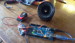
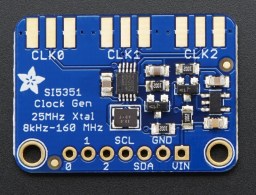
[Tom] used a Teensy 3.1 Arduino compatible board, to control the Si5351 mounted on an Adafruit breakout board. An LCD display shows the current frequency and provides a simple interface display for changing the output. A dial encoder allows for direct adjustment of the frequency. The ham frequency band and the frequency increment for each encoder step are controlled by a joystick. When you get into the 10 meter band you definitely want to be able to jump by kHz increments, at least, since the band ranges from 28 mHz to 29.7 mHz.

So what is the Si5351? The data sheets calls it an I2C-Programmable Any-Frequency CMOS Clock Generator + VCXO. Phew! Let’s break that down a bit. The chip can be controlled from a microprocessor over an I2C bus. The purpose of the chip is to generate clock outputs from 8 kHz to 160 kHz. Not quite any frequency but a pretty good range. The VCXO means voltage controlled crystal oscillator. The crystal is 25 mHz and provides a very stable frequency source for the chip. In addition, the Si5351 will generate three separate clock outputs.

[Tom] walks through the code for his VFO and provides it via GitHub. An interesting project with a lot of the details explained for someone who wants to do their own hacks. His work is based on work done by others that we’ve published before, which is what hacking is all about.


Filed under: Arduino Hacks, radio hacks

This Trippy Arduino-Powered “Plant” Trains Your Brain

Ever wish you could synchronize your brainwaves with an otherworldly luminescent plant from the comfort of your own room?

Read more on MAKE

The post This Trippy Arduino-Powered “Plant” Trains Your Brain appeared first on Make: DIY Projects, How-Tos, Electronics, Crafts and Ideas for Makers.

Arduino-compatible software for FRDM-KL25Z board

As many of you have realized, I’m finding that doing multiple-platform support for the PteroDAQ system is a bit annoying.  One irritation is that the mbed.org compiler for the FRDM-KL25Z board is not integrated with the other compilers—not even sharing the same file system.  So every time I make a change, I need to transfer all the files between my laptop and the mbed website—I can’t use mercurial or git to keep things in sync.

All the other boards I’m using can be compiled for locally and downloaded to with the Arduino IDE.  It is not a particularly powerful IDE, but it is dead simple to use, and it runs on my old Mac OS 10.6.8 (at least, if I use Arduino 1.0.6—the newer versions seem to assume new Macs).  A lot of the “professional” IDEs assume that you replace your computer every year and have the latest OS installed, or that you use nothing but Windows.

Since the FRDM KL25Z board is currently one of the best price/feature microcontroller boards on the market, I figured that someone must be working on an Arduino plug-in for the hobbyist market.  So I did some Google searches and found something that initially looked promising: Arduino-compatible software library for FRDM-KL25Z board – CodeProject.

FRDM-KL25Z is an interesting ultra low cost board with 32-bit microcontroller. What makes it interesting for the Do-It-Yourself community is low price (about $13) and also the compatibility with the Arduino pinout. If you are Arduino user like me, you will probably also feel interest if you hear about a board which could, for less than half the price of standard Arduino board, give you a 32-bit ARM MCU running at 48 MHz with 128 KB of FLASH and 16 KB of RAM memory, on-board accelerometer and more. But as you might have expected, there is a “catch”. The  FRDM board has the same layout of pins, so you can connect the Arduino shields to it, but there is no software compatibility. You cannot use the Arduino API functions such as digitalRead, delay, etc. and you cannot program the board from the Arduino IDE. I was thinking it would be nice if you could… And this article is my first step in this direction.

Digging deeper, though, disappointed me.  They are trying to provide the trivial parts of the Arduino API, but they do their compiling with Kinetis Design Studio (which doesn’t run on Mac OS 10.6.8, and which is supposedly a bit of a bear to learn to use).  I’m more interested in the opposite combination—using the Arduino IDE, with only minimal use of the Arduino API (which I find a bit too inefficient for my tastes), except for a couple of difficult things (like the USB stack).

They’ve also licensed their code with a contagious LGPL license, which is too restrictive for the PteroDAQ code.

What I’m looking for is something like the Teensyduino implementation, but for the FRDM KL25Z board. I’ll have to look at how the Teensy loader is integrated into the Arduino IDE—if I can figure out how to put in copying a .bin or .s19 file to an emulated flash drive instead, then I can probably program for the KL26Z board, and possibly for the KL25Z board.


Filed under: Circuits course Tagged: Arduino, KL25Z, KL26Z, PteroDAQ, Teensy

PteroDAQ boards

I took a photograph this afternoon of three of the boards that can be used with the PteroDAQ data acquisition system:

On the left is the Arduino Leonardo, the slowest and most expensive of the boards here. In the middle is the KL25Z, which I’ve been using in my class for a couple of years—it is the cheapest and most featureful of the boards. On the right is the Teensy 3.1 (without headers yet), which is the fastest and smallest of the supported boards.

I’m considering switching to the Teensy 3.1 for the class, despite its higher price than the KL25Z board, because adding male headers to the bottom of the board makes it possible to plug the Teensy 3.1 into a bread board, which makes for more secure wiring than running separate wires to the KL25Z board.  We don’t really need the 64 pins of the KL25Z board, we’re not mounting Arduino shields, and we’re not using the accelerometer or the touch sensor, so the main question is whether it is better to have the data-acquisition board be standalone or be inserted into a bread board. The RGB light on the KL25Z board is a nice feature for providing feedback that is missing from the other boards (which only have a single-color LED).

I’ve also thought about usefulness to the students after the course, though few of the students will go on to do anything other than PteroDAQ with the boards.  The Arduino IDE is much easier to deal with for beginners than any of the development environments for the KL25Z, and Teensyduino is pretty easy to install on top of the Arduino environment.  So if students are going to go on to do hobbyist-level programming on the boards, then an Arduino board or the Teensy 3.1 might be a better choice. Given how much more powerful the Teensy 3.1 is than the old ATMega-based Arduinos, I see no reason to recommend buying Arduino boards (though clones from China have gotten down to about $3).

Erich Styger, in a comment, mentioned that he is frustrated by the Teensy’s lack of a SWD (serial wire debug) connector, which he is used to using for debugging. Since I’m from an older generation of programmers, I don’t miss it—I’ve not used the SWD connector on the KL25Z boards (though my son has, to use the OpenSDA chip as a programmer).  For me, it is a luxury to have a serial port for getting print messages from the board—I started microprocessor programming in the days when having one or two LEDs was about all the information you got back from the board. Having debuggers like GDB was a luxury available on computers that cost thousands of dollars.

Of course, the ARM processors on the Teensy 3.1 and the FRDM KL25Z boards are very much more complicated than the old 8080A, Z80, and 6800 8-bit processors I started with, and people are writing much larger programs for them, so I can see the advantage of having a debugger. But there is a large startup cost to learning to use a debugger and setting up the complicated software development tools they expect you to use, so I’m happy recommending the very limited, but easy-to-use Arduino interface for bioengineering students who want to go a bit further.

I’m curious what my readers think about the choice between a FRDM KL25Z board and a Teensy 3.1 board for the Applied Electronics class, given that most of the students will only use the boards for that class.  What tradeoffs might I have missed?  If you were in the class, which board would you rather work with?


Filed under: Circuits course, Data acquisition Tagged: Arduino, debugger, KL25Z, Leonardo, PteroDAQ, Teensy

PteroDAQ supports Teensy 3.1

In one day my son and I added support for the Teensy 3.1 board to the PteroDAQ data acquisition system that previously supported the Freedom KL25Z board and the ATMega-based Arduino boards.

We ended up using the Teensyduino development system, but really only for the downloading and for the usb-serial library, since the K20 ARM chip on the Teensy 3.1 is quite similar to the KL25 that we originally based things on.

The Teensy 3.1 is a lot easier to install the software on than the Freedom boards, and runs a little faster (72MHz instead of 48MHz), but has essentially the same ADC.  Actually, it has 2 analog-to-digital converters, but most of the pins can only be read by ADC0, so we’ve not set up ADC1 to read anything but the internal 1.2V Vref (which is conveniently provided as an output on the AREF pin).  We had originally planned to use just ADC0, but the code for reading the Vref signal on ADC0 never worked—I suspect an error in the reference manual, since changing to reading Vref with ADC1 worked fine.

The Freedom boards are cheaper, are easier to unplug the USB cables from, can deliver more power at 3.3V, have RGB LED, and have a lot of neat features missing from the Teensy boards, but the Teensy boards can be configured to plug directly into a bread board (if you give up a lot of the connections and just use 26 pins), and have more RAM (so can run for longer at high sampling rates before the buffer overflows).

I’m going to have to rewrite part of my book to talk about the possibility of using the Teensy 3.1, and I’ll have to decide whether the extra $6–$7 is worth the simpler setup for my Applied Electronics lab course. We’d sacrifice being able to get much power from the board (probably only about 100mA instead of 500mA at 3.3V), but that is a relatively minor loss, since we have bench power supplies at every station.

I’m not sure what I’ll recommend in the book for people trying to learn on their own—I’ll probably have to play with the Teensy a bit to see how useful it is.  I have at least one other program that the students have been using in the lab (the frequency detector for turning a relaxation oscillator into a touch sensor) that I’ll have to port to Arduinos and the Teensy 3.1.

For home hobbyists who aren’t planning to dive deep into embedded-system programming, the Teensyduino IDE is a lot friendlier than the MBED.ORG tools (and I hear that the Kinetis SDK has a very, very large learning curve), so it might be a better board despite the lack of peripherals (no accelerometer, RGB LED, or capacitive touch slider).


Filed under: Circuits course, Data acquisition Tagged: Arduino, data acquisition, KL25Z, PteroDAQ, Teensy

Using A TeensyLC To Emulate The XBOX 360 Controller

After the release of Mortal Kombat X, [Zachery’s] gaming group wanted to branch out into the fighter genre. They quickly learned that in order to maximize their experience, they would need a better controller than a standard gamepad. A keyboard wasn’t going to cut it either. They wanted a fight stick. These are large controllers that look very much like arcade fighting controls and include a joystick and large buttons. [Zachery’s] group decided to build their own fight stick for use with a PC.

[Zachery] based his build around the TeensyLC, which is a 32 bit development board with an ARM processor. It’s also compatible with Arduino. The original version of his project setup the controller as a HID, essentially emulating a keyboard. This worked for a while until they ran into compatibility issues with some games. [Zachery] learned that his controller was compatible with DirectInput, which has been deprecated. The new thing is Xinput, and it was going to require more work.

Using Xinput meant that [Zachery] could no longer use the generic Microsoft HID driver. Rather than write his own drivers, he decided to emulate the XBOX 360 controller. When the fight stick is plugged into the computer, it shows up as an XBOX 360 controller and Windows easily installs the pre-built driver. To perform the emulation, [Zachery] first had to set the VID and PID of the device to be identical to the XBOX controller. This is what allows the Microsoft driver to recognize the device.

Next, the device descriptor and configuration descriptor had to be added to the Teensy’s firmware. The device descriptor includes information such as USB version, device class, protocol, etc. The configuration descriptor includes additional information about the device configuration. [Zachery] used Microsoft Message Analyzer to pull the configuration descriptor from a real XBOX 360 controller, then used the same data in his own custom controller.

[Zachery] programmed the TeensyLC using the Arduino IDE. He ran into some trouble here because the IDE did not include the correct device type for an Xinput device. [Zachery] had to edit the boards.txt file and add three lines of code in order to add a new hardware device to the IDE’s menu. Several other files also had to be modified to make sure the compiler knew what an Xinput device type was.  With all of that out of the way, [Zachery] was finally able to write the code for his controller.


Filed under: Arduino Hacks, ARM
Hack a Day 15 Jul 03:00