Now that I have a power resistor and heatsink, and have verified that my power supply is capable of delivering 50W, I can try making a thermal control system for an incubator box as I hope to get the freshman design class to do.
Before building a complete control system and tuning a proportional, PI, or PID controller, I decided to check each of the components:
- 1.8Ω resistor and heatsink (already characterized in still air in the previous post). Initially I was going to use the 8.2Ω resistor, but it heated so slowly once bolted to the heatsink that I wasn’t sure that students would have the patience to wait for it—they might conclude that things weren’t working.
- NTD4858N-35G nFET for PWM control of the heater.
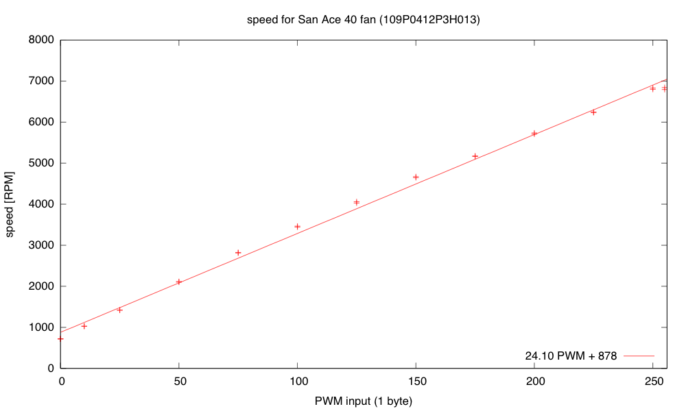
- fan. I bought a SanAce 40 109P0412P3H013 fan with PWM control and tachometer feedback, and I wanted to be sure that I could control the fan speed and read the tachometer.
- thermistor. I had some NTCLE100E3103JB0 thermistors around that I had never used. They’re not ideal for measuring temperature of resistors (they only go up to 125°C), but they should be find for measuring air temperature around 35°C, which is what the incubator will mainly be used at.
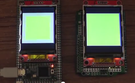
- Arduino board (actually a SparkFun RedBoard, which is plug-compatible with the Uno R3, but has has a more reliable USB interface and is slightly cheaper.
I started out hooking up the nFET and the 1.8Ω resistor and making sure that the nFET did not get too hot. It seems to be ok. When I was using the 8.2Ω resistor, I measured the voltage drop across the resistor and the across the nFET, getting a 57.6mV drop from drain to source, with a current of about 9.024V/8.21ohm = 1.099A. That’s about a 52mΩ on-resistance, and I was expecting more like 7mΩ–10mΩ. My gate voltage was around 5V (bigger than the 4.5V of the data sheet), which should have given me lower on-resistance. The only things I can think of are that I had more wiring resistance than I realized (quite likely, but not likely enough to add over 40mΩ), and that I was measuring around 1A, not around 10A, so perhaps there is a small-voltage effect that I don’t know about.
I should probably test the voltage drop again with 1.8Ω resistor, and see whether the on-resistance is still so high. Better probe placement may get me more accurate voltage measurements also.
The fan runs fine at 9.212V at about 6850 RPM. Setting the PWM input line of the fan to 0 drops the speed to about 710RPM, and setting the PWM duty cycle to a half sets the speed at about 4120RPM. The fan is a bit noisy for such a tiny fan at the highest speed setting, but reasonably quiet at lower speeds. I suspect that bolting the fan to a piece of masonite as a baffle would reduce the fan noise, as I think quite a bit of it was from vibration between the case of the fan and the metal plate it was sitting on.
The tachometer on the fan provides an open-collector output that I read with an interrupt input on the Arduino (pin 2, interrupt 0). I recorded the time between interrupts and converted it an RPM measurement. The tachometer worked fine when I was just using the fan, or when the resistor was either completely off or completely on, but when I tried using PWM on the resistor, the tachometer readings became nonsense.
I looked at the tachometer signal with my oscilloscope and saw that the PWM transitions for the resistor resulted in huge spikes in the tachometer output that triggered extraneous interrupts. I suspected noise coupled through the power supply. Adding a 10µF bypass capacitor to the 9V power supply to the fan reduced the problem considerably, and a 470µF aluminum polymer electrolytic cleaned up the power supply even more. The 10µF alone was enough to eliminate the extraneous spikes in the middle.
I think that I should try adding some gate resistance to the nFET to slow down the rise and fall of the PWM signal a little, to reduce the inductive spikes and make the bypass capacitors more effective.
I noticed that I was still getting some readings that were half the duration that I was expecting. These could have been caused by ringing at the other transition of the tachometer pulse, so I tried eliminating the ringing by adding some capacitance to the line and changing the pullup resistor. These attempts were not very successful, so I decided that hysteresis was needed. I put a Schmitt trigger between the open-collector output and the Arduino interrupt input, and the signal got a lot cleaner. There were occasional double pulses at one edge, though, but I found that adding a 1nF to 10nF capacitor in parallel with the pullup resistor for the open collector output smoothed out the high frequency noise enough to get clean, single transitions out of the Schmitt trigger.
I hooked up the thermistor in a voltage divider with 5.1kΩ on the other leg (which maximizes the dV/dT sensitivity at 40.1°C). I used the parameters on the data sheet to plot a calibration curve for the thermistor:
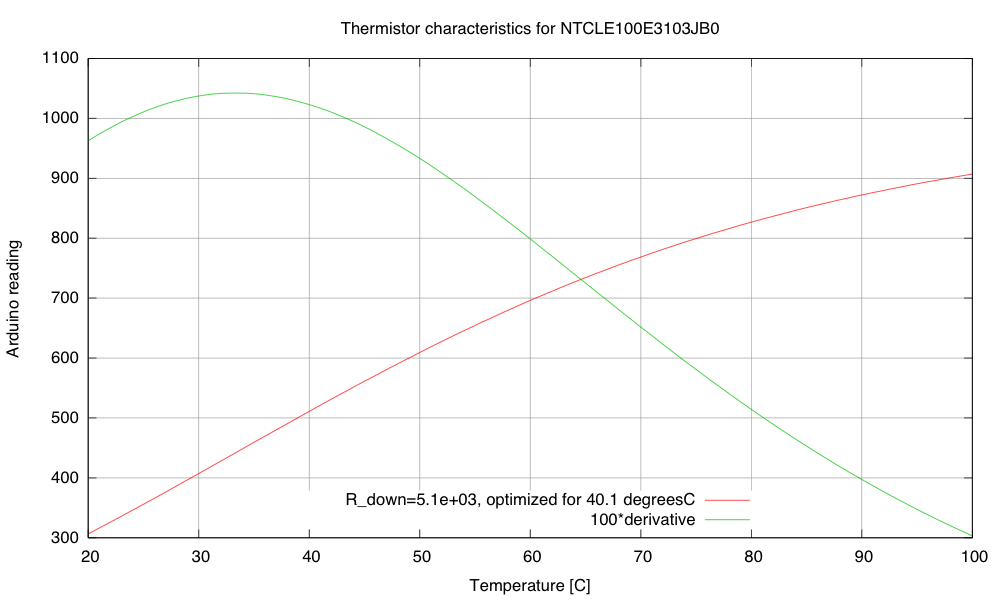
Calibration and sensitivity curves for the thermistor, based on the data sheet and a 5.1kΩ pulldown resistor.
The maximum sensitivity of the thermistor circuit is around 33.3 degrees C (~10.4 Arduino LSB/°C). That’s not a very high sensitivity, particularly given the noise of the ADC. Note that maximizing the slope at 40.1 °C is not the same thing and having the maximum of the slope at 40.1°C. If the maximum of the slope was at 40.1°C, the slope there would be less than it is in this plot.
My son wonders why I’m using the Arduino board for this project, rather than the FRDM-KL25Z board that I use for the circuits class or the Teensy 3.1 ARM development board. The ARM processors have more power, more memory, and much better analog-to-digital converters—and the KL25Z board is cheaper. If I were doing this project for myself, I would certainly prefer the KL25Z board. But it is a little harder to get a beginner started on that board—just getting the first program onto the board is a pain if you don’t have a Windows machine (due to the broken bootloader the P&E Micro wrote). There are instructions now for replacing the firmware from a Linux system, but I’ve not checked yet whether these instructions work from a Mac. Even once you get working firmware onto the boards, the development environments are not beginner-friendly. Well, that is certainly true of the MBED environment or bare-metal ARM environment for the KL25Z boards, but the Teensy 3.1 board supposedly can be programmed from a plugin for the Arduino IDE, which might be simple enough for beginners. This is something for me to look into more.
Of course, one reason I’m using the Arduino Uno or Sparkfun RedBoard is that they are 5V processors, and most of the power nFETs I’ve looked at need 4.5V on the gate to turn on fully. There are power nFETs now with lower gate voltages, but most of them are only available as surface-mount devices. I don’t want to have to add an extra transistor or buffer chip as a level changer for the PWM circuit.
The problem is that these students will be brand new to programming, brand new to electronics, and brand new to engineering—and the course is only a 2-unit course, not a full 5-unit course, so the total time students are expected to spend on the course is only 60 hours. I want them to be able to design stuff quickly, without spending all their time learning to use tools or trying to find workarounds for limitations of the devices they are using. It already bothers me that they’ll probably need to use a Schmitt trigger to clean up the tachometer input, but at least hysteresis was a topic I was planning to cover! (The need for bypass capacitors bothers me less—they are so ubiquitous in electronics that I’ll have to cover them no matter what.)
It’s after midnight now, so I’m going to call it a day. Here is my to-do list on this project:
- Check the VDS voltage at 4A on the nFET. Is the on-resistance still much too high?
- Try adding a 1kΩ gate resistance to slow down the transitions on the PWM, to see if that reduces the inductive spikes and the noise-coupling through the 9V power supply.
- Write a simple control loop for the fan speed, so that the fan speed can be held constant even when the power-supply voltage changes. This may be an opportunity to try the P/PI/PID tuning, since the control loop should be fairly fast.
- Write a simple control loop for controlling the temperature at the thermistor, by adjusting the PWM for the resistor. This might get messy, as the fan speed probably affects the rate of transfer from the resistor to the thermistor (the thermistor is in the air stream blown over the resistor, not touching the resistor).
- Put the whole thing into a styrofoam box, to see whether extra venting is needed to allow things to cool down, and to see how tightly temperature can be controlled.
- Design and build baffling for the fan to get better airflow in the box.
- Figure out how to get students to come up with workable designs, when they are starting from knowing nothing. I don’t want to give them my designs, but I want to help them find doable subproblems. Some of the subproblems they come up with may be well beyond the skills that they can pick up in the time frame of the course.
Filed under:
freshman design seminar Tagged:
Arduino,
fan,
incubator,
KL25Z,
power resistor,
PWM,
tachometer,
Teensy,
thermistor