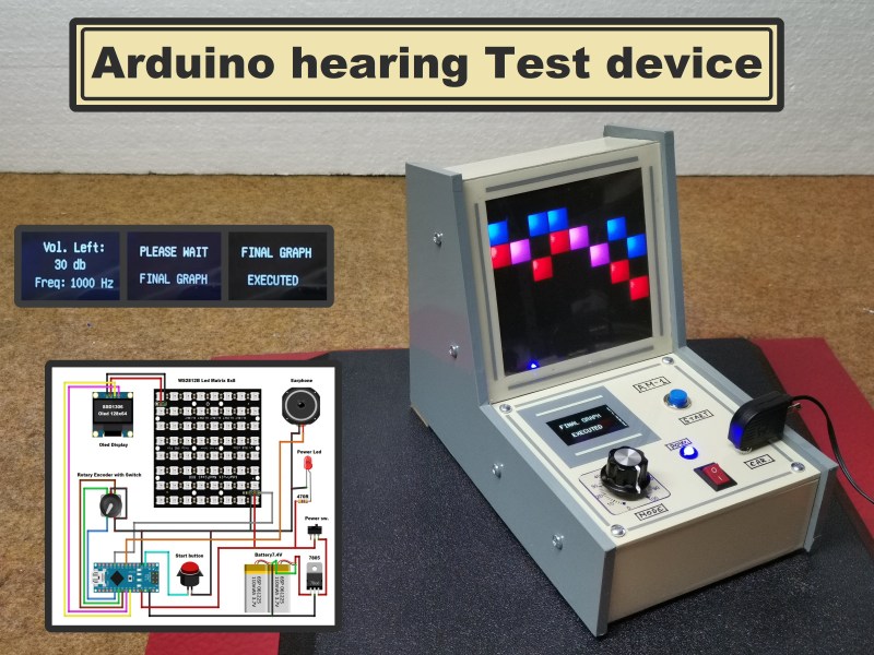
DIY Arduino Hearing Test Device
Hearing loss is a common problem for many – especially those who may have attended too many loud concerts in their youth. [mircemk] had recently been for a hearing test, and noticed that the procedure was actually quite straightforward. Armed with this knowledge, he decided to build his own test system and document it for others to use.
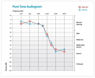
By using an Arduino to produce tones of various stepped frequencies, and gradually increasing the volume until the test subject can detect the tone, it is possible to plot an audiogram of hearing threshold sensitivity. Testing each ear individually allows a comparison between one side and the other.
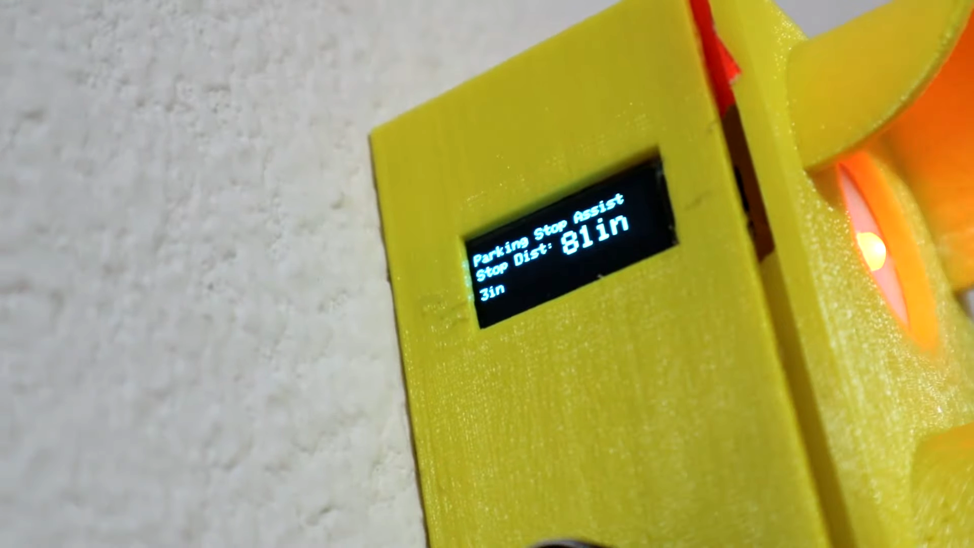
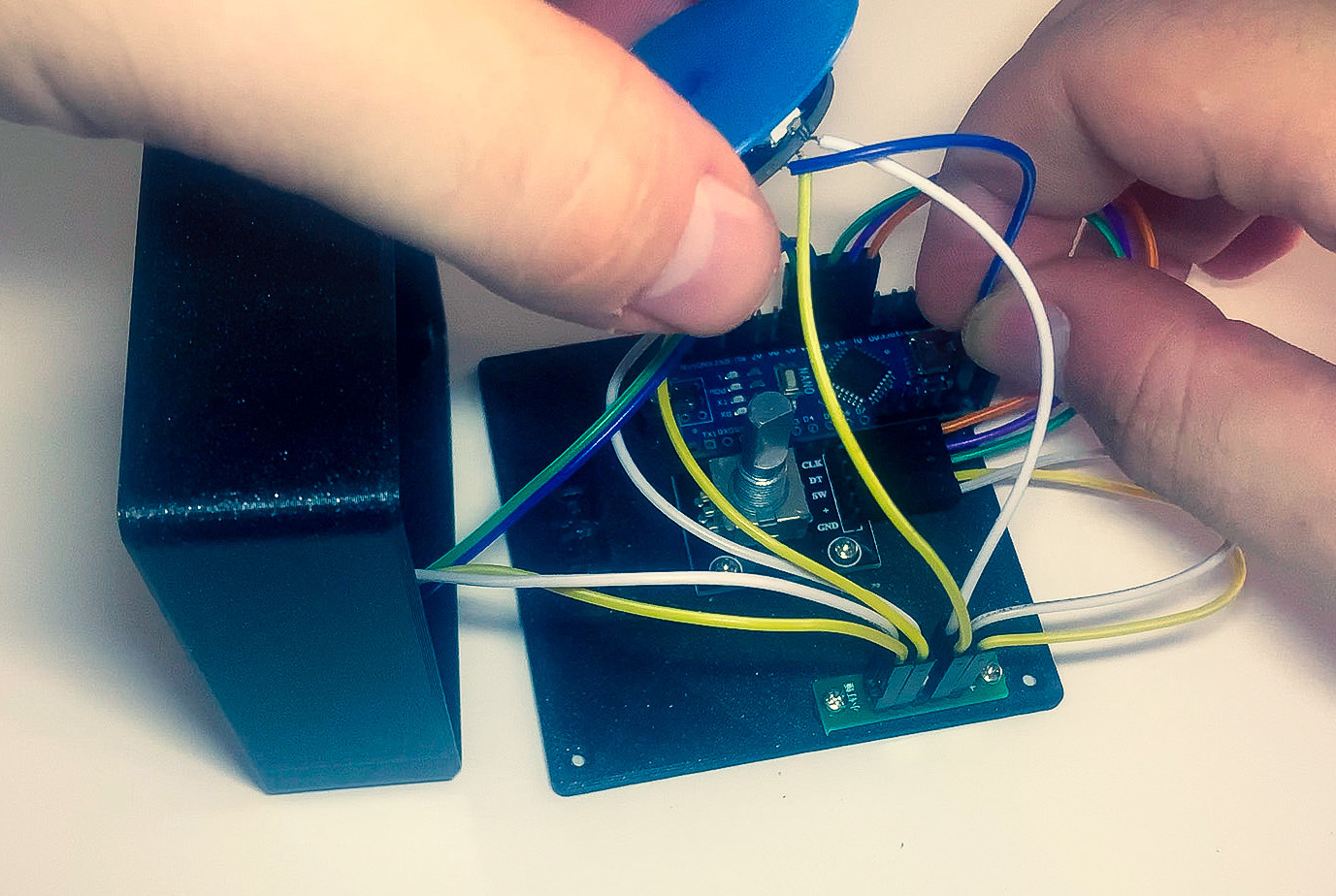
[mircemk] has built a nice miniature cabinet that holds an 8×8 matrix of WS2812 addressable RGB LEDs. A 128×64 pixel OLED display provides user instructions, and a rotary encoder with push-button serves as the user input.
Of course, this is not a calibrated professional piece of test equipment, and a lot will depend on the quality of the earpiece used. However, as a way to check for gross hearing issues, and as an interesting experiment, it holds a lot of promise.
There is even an extension, including a Class D audio amplifier, that allows the use of bone-conduction earpieces to help narrow down the cause of hearing loss further.
There’s some more information on bone conduction here, and we’ve covered an intriguing optical stimulation cochlear implant, too.
 The first thing to catch one’s eye might be that leftmost seven-segment digit. There is a simple reason it doesn’t match its neighbors: [Juan] had to use what he had available, and that meant a mismatched digit. Fortunately, 3D printing one’s own enclosure meant it could be gracefully worked into the design, instead of getting a Dremel or utility knife involved. The next is a bit less obvious: the display lacked a decimal point in the second digit position, so an LED tucked in underneath does the job. Finally, the knob on the right could reasonably be thought to be a rotary encoder, but it’s actually connected to a small DC motor. By biasing the motor with a small DC voltage applied to one lead and reading the resulting voltage from the other, the knob’s speed and direction can be detected, doing a serviceable job as rotary encoder substitute.
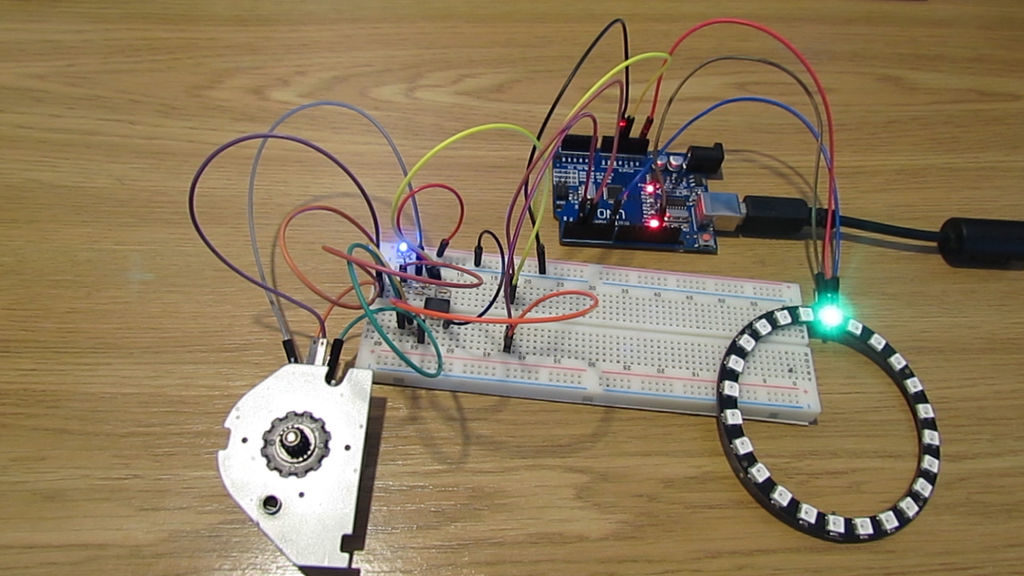
 In a project, repetitive tasks that break the flow of development work are incredibly tiresome and even simple automation can make a world of difference. [Simon Merrett] ran into exactly this while testing different stepper motors in a strain-wave gear project. The system that drives the motor accepts G-Code, but he got fed up with the overhead needed just to make a stepper rotate for a bit on demand. His solution? A