Posts with «rgb» label

Mini Meters Monitor Microprocessor Maximization

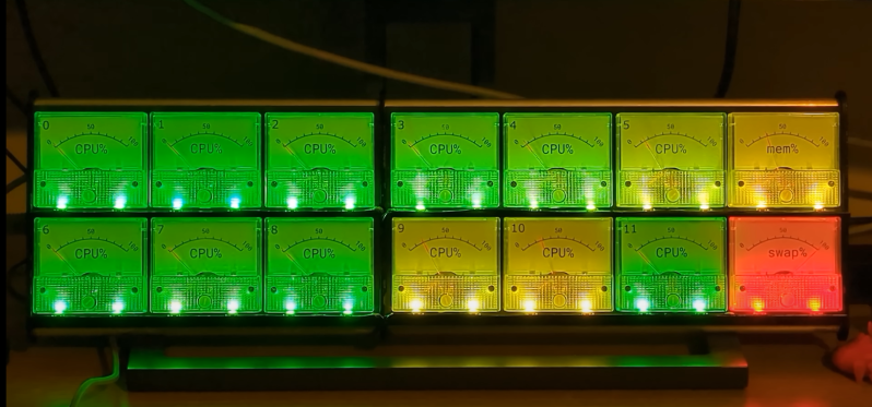
[Lex] over at Computing: The Details loves to make fun projects. Recently, he’s created a hardware CPU monitor that allows him to see how well his PC is parallelizing compile tasks at a glance. The monitor is built from 14 analog meters, along with some WS2812 RGB LEDs.

Each meter represents a core on [Lex]’s CPU, while the final two meters show memory and swap usage. The meters themselves are low-cost 5 mA devices. Of course, the original milliamps legends wouldn’t do much good, so [Lex] designed and printed graduations that glue over the top. The RGB LED strip is positioned so two LEDs fit under each meter. The LEDs allow a splash of color to draw attention to the current state of the machine. The whole bank going red would sure get our attention!

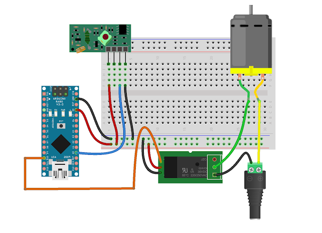
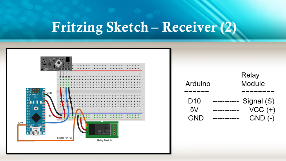
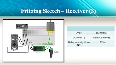
The system is controlled by an Arduino Mega, with the meters driven using the PWM pins. The only extra part is a 1 K resistor. The Arduino wrangles the LEDs as well. Sadly [Lex] did not include his software. He did describe it though. Basically he’s using a Rust program to call systemstat, obtaining the current CPU utilization data in Linux. A bit of math converts this into pointer values and LED colors. The data is then sent via USB-serial to the Arduino Mega. The software savvy will say it’s pretty easy to replicate, but the hardware only hackers among us might need a bit of help.

This isn’t the first custom meter we’ve seen on Hackaday. Your author’s first project covered by Hackaday was for a meter created using an automotive gauge stepper motor. I didn’t include source code either – but only because [Guy Carpenter]’s Switec X25 library had me covered.

Thanks for the tip, [TubeTime]!

Mini Library for Kids Gets Blinky Lights and Solar Upgrade

Reading is big in Québec, and [pepelepoisson]’s young children have access to a free mini library nook that had seen better days and was in dire need of maintenance and refurbishing. In the process of repairing and repainting the little outdoor book nook, he took the opportunity to install a few experimental upgrades (link in French, English translation here.)

The mini library pods are called Croque-Livres, part of a program of free little book nooks for children across Québec (the name is a bit tricky to translate into English, but think of it as “snack shack, but for books” because books are things to be happily devoured.)

After sanding and repairs and a few coats of new paint, the Croque-Livres was enhanced with a strip of WS2812B LEDs, rechargeable battery with solar panel, magnet and reed switch as door sensor, and a 3.3 V Arduino to drive it all. [pepelepoisson]’s GitHub repository for the project contains the code and CAD files for the 3D printed pieces.

The WS2812B LED strip technically requires 5 V, but as [pepelepoisson] found in his earlier project Stecchino, the LED strip works fine when driven directly from a 3.7 V lithium-polymer cell. It’s not until around 3 V that it starts to get unreliable, so a single 3.7 V cell powers everything nicely.

When the door is opened, the LED strip lights up with a brief animation, then displays the battery voltage as a bar graph. After that, the number of times the door as been opened is shown on the LED strip in binary. It’s highly visual, interactive, and there’s even a small cheat sheet explaining how binary works for anyone interested in translating the light pattern into a number. How well does it all hold up? So far so good, but it’s an experiment that doesn’t interfere at all with the operation of the little box, so it’s all good fun.

Hack a Day 28 Jun 21:00

A Farewell To YouTube Sub Counters Set To Break With API Change

Of all the things you never would have guessed you’d need just ten years ago, a YouTube subscriber counter would probably rank highly. You would have guessed that the little hits of dopamine accompanying each tick upward of a number would be so addictive?

As it turns out, lots of people wanted to keep a running total of their online fans, and a bewilderingly varied ecosystem of subscriber counters has cropped up. All of them rely on the API that YouTube exposes for such purposes, which as [Brian Lough] points out is about to change and break every subscription counter ever made. In the YouTube sub counter space, [Brian] is both an enabler – he built an Arduino wrapper to fetch YT sub counts easily – and a serial builder of displays for other YouTubers. The video below shows a collection of his work, many based on RGB LED matrix display, like the one used in his Tetris-themed sub counter. They’re all well-built, nice to look at, and sadly, destined for obsolescence sometime in August when the API changes.

The details of the API changes were made public in April, and for the subs count it amounts to rounding the count and displaying large counts as, for instance, 510k as opposed to 510,023. We’re confident that [Brian] and other display builders will be able to salvage some of their counters with code changes, but others will probably require hardware changes. Thanks, YouTube.

Hack a Day 02 Aug 03:00

Unique Clock Keeps Time the Fibonacci Way

You say your binary clock no longer has the obfuscation level needed to earn the proper nerd street cred? Feel like you need something a little more mathematically challenging to make sure only the cool kids can tell the time? Then this Fibonacci clock might be just the thing to build.

Granted, [TecnoProfesor]’s clock is a somewhat simplified version of an earlier version that was nigh impossible to decode. But with its color coding and [Piet Mondrian]-esque grids, it’s still satisfyingly difficult to get the time from a quick glance. The area of the blocks represents the Fibonacci sequence 1, 1, 2, 3, 5, and adding up which blocks are illuminated by the RGB LEDs behind the frosted front panel. That lets you tally up to 12 intervals; for the minutes and seconds, there are indicators for the powers of 12 up to 48. Put it all together and you’ve got a unique and attractive graphical time display that’s sure to start interesting conversations when the mathematically disinclined try to use it. Check out the video below as the clock goes from 12:28:01 to 12:28:46. We think.

If this doesn’t scratch your itch for obfuscated clocks, we’ve got plenty of them. From random four-letter words to an analog digital clock to an epic epoch clock, we’ve got them all.

A Ping Pong Ball LED Video Wall

Constrained builds are often the most fun. Throw an artificial limit into the mix, like time limiting your effort or restricting yourself to what’s on hand, and there’s no telling what will happen.

[bitluni] actually chose both of those constraints for this ping pong ball LED video display, and the results are pretty cool, even if the journey was a little rough. It seems like using sheet steel for the support of his 15 x 20 Neopixel display was a mistake, at least in hindsight. A CNC router would probably have made the job of drilling 300 holes quite a bit easier, but when all you have is a hand drill and a time limit, you soldier on. Six strings of Neopixels fill the holes, a largish power supply provides the 18 or so amps needed, and an Arduino knock-off controls the display. The ping pong ball diffusers are a nice touch, even if punching holes in them cost [bitluni] a soldering iron tip or two. The display is shown in action in the video below, mostly with scrolling text. If we may make a modest suggestion, a game of Pong on a ping pong ball display might be fun.

[bitluni] says that the display is on its way to Maker Faire Berlin this weekend, so stop by and say hi. Maybe he’ll have some of his other cool builds too, like his Sony Watchman Game Boy mashup, or the electric scooter of questionable legality.

Hack a Day 17 May 16:30

Crawling a Dungeon, 64 Pixels at a Time

The trend in video games is toward not being able to differentiate them from live-action theatrical releases, and games studios are getting hard to tell from movie studios. But quality graphics don’t always translate into quality gameplay, and a lot can be accomplished with minimalist graphics. Turn the clock back a few decades and think about the quarters sucked up by classics like Pac-Man, Space Invaders, and even Pong if you have any doubts about that.

But even Pong had more than 64 pixels to work with, which is why this dungeon-crawler game on an 8×8 RGB matrix is so intriguing. You might think [Stolistic]’s game would be as simple as possible but think again. The video below shows it in action, and while new users will need a little help figuring out what the various colors mean, the game is remarkably engaging. The structure of the dungeon is random with multiple levels to unlock via the contents of power-up chests, and there are mobs to battle in a zoomed-in display. The game runs on an Arduino Uno and the matrix is driven by a bunch of 74HC595 shift registers.

It’s fun to see what can be accomplished with as little as possible. Looking for more low-res goodness? Check out this minimalist animated display, or a Geiger counter with a matrix display.

Hack a Day 06 May 06:00

RGB Disk Goes Interactive with Bluetooth; Shows Impressive Plastic Work

[smash_hand] had a clear goal: a big, featureless, white plastic disk with RGB LEDs concealed around its edge. So what is it? A big ornament that could glow any color or trippy mixture of colors one desires. It’s an object whose sole purpose is to be a frame for soft, glowing light patterns to admire. The disk can be controlled with a simple smartphone app that communicates over Bluetooth, allowing anyone (or in theory anything) to play with the display.

The disk is made from 1/4″ clear plastic, which [smash_hand] describes as plexiglass, but might be acrylic or polycarbonate. [smash_hands] describes some trial and error in the process of cutting the circle; it was saw-cut with some 3-in-1 oil as cutting fluid first, then the final shape cut with a bandsaw.

The saw left the edge very rough, so it was polished with glass polishing compound. This restores the optical properties required for the edge-lighting technique. The back of the disc was sanded then painted white, and the RGB LEDs spaced evenly around the edge, pointing inwards.

The physical build is almost always the difficult part in a project like this — achieving good diffusion of LEDs is a topic we talk about often. [smash_hands] did an impressive job and there are never any “hot spots” where an LED sticks out to your eye. With this taken care of, the electronics came together with much less effort. An Arduino with an HC-05 Bluetooth adapter took care of driving the LEDs and wireless communications, respectively. A wooden frame later, and the whole thing is ready to go.

[smash_hands] provides details like a wiring diagram as well as the smartphone app for anyone who is interested. There’s the Arduino program as well, but interestingly it’s only available in assembly or as a raw .hex file. A video of the disk in action is embedded below.

Making LED lighting interactive comes in many different shapes and forms, and as the disk above shows, shifting color patterns can be pleasantly relaxing.

A Wordsearch Twist on the Word Clock

We love seeing new takes on existing ideas, and [Danny] certainly took the word clock concept in an unusual direction with his Wordsearch Clock. Instead of lighting up words to spell out the time, [Danny] decided to embrace the fact that the apparent jumble of letters on the clock face resembles a word search puzzle.

In a word search puzzle, words can be found spelled forward or backward with letters lined up horizontally, diagonally, or vertically. All that matters is that the correct letters are in a line and sequentially adjacent to one another. [Danny]’s clock lights up the correct letters and words one after the other, just as if it were solving a word search puzzle for words that just happen to tell the correct time. You can see it in action in the video, embedded below.

[Danny] went the extra mile in the planning phase. After using a word search puzzle generator tool to assist in designing the layout, he wrote a Processing sketch to simulate the clock’s operation. Visually simulating the clock allowed him to make tweaks to the layout, identify edge cases to address, and gain insight into the whole process. If you’re interested in making your own, there is a GitHub repository for the project.

Word Clocks are a great place to see innovation; you can go small like this micro word clock, you can push the concept for all it’s worth by adding heaps of weather data, or just go the extra mile on presentation like this walnut-finish clock.


Filed under: clock hacks
Hack a Day 17 Mar 03:00

Prextron CHAIN BLOCKS - Arduino Nano controlled Ultrasonic sensor that switches a motor wirelessly using 433MHz RF modules and a relay board.


Description

In this tutorial, I will be evaluating Prextron CHAIN blocks – a new system that allows you to connect your sensors and actuators to an Arduino NANO using clever 3D-printed prototyping boards that can be stacked sideways. This very modular system makes it easy to connect, disconnect and replace project components, and eliminate the “rats nest of wires” common to many advanced Arduino projects. CHAIN BLOCKS are open, which means that you can incorporate any of your sensors or actuators to these prototyping boards, and you can decide which specific pin on Arduino you plan to use. The CHAIN BLOCK connections prevent or reduce common connection mistakes, which make them ideal for class-room projects and learning activities.

I am going to set up a project to put these CHAIN BLOCKs to the test:
When I place my hand in-front of an Ultrasonic sensor, the Arduino will transmit a signal wirelessly to another Arduino, and consequently turn on a motor.


Parts Required:

You need the following Prextron Chain Blocks


Please note: You may need to solder the module wires to the CHAIN BLOCK protoboard.


Arduino Libraries and IDE

This project does not use any libraries. However, you will need to upload Arduino code to the Arduino. For this you will need the Arduino IDE which can be obtained from the official Arduino website:
https://www.arduino.cc/en/main/software


ARDUINO CODE: RF Transmitter


ARDUINO CODE: RF Receiver


Fritzing diagrams for Transmitter


Fritzing diagrams for Receiver


Concluding comments

The purpose of this project was to evaluate Prextron CHAIN BLOCKs and put them to the test. Here is what I thought of CHAIN BLOCKS at the time of evaluation. Some of my points mentioned below may no longer apply to the current product. It may have evolved / improved since then. So please take that into consideration


What I liked about Chain Blocks

  • The design is simple, the product is simple.
  • Once the Chain Blocks were all assembled, they were very easy to connect to each other.
  • I can really see the benefit of Chain Blocks in a teaching environment, because it simplifies the connection process, and reduces connection mixups.
  • It was good to see that the blocks come in different colours, which means that you can set up different colour schemes for different types of modules.
  • You can incorporate pretty much any sensor or Actuator into the Chain block which is very appealing.
  • You also have the flexibility of choosing which pins you plan to use on the Arduino.
  • Projects look a lot neater, because you no longer have the rats nest of wires.
  • The Blocks lock into each other which means that they are much easier to transport/carry.


What I did not like about Chain Blocks

  • In most cases, the Chain Block protoboard lanes were not numbered, which increased the chances of making mistakes when soldering
  • The need to solder modules to the protoboard, may be a discouragement for some people.
  • I would have liked a choice of different size Chain blocks. Some of the sensors did not fit nicely into the Square blocks.
  • Prextron really need to work on their website if they plan to get serious with this product: Webpage has incomplete functionality or irrelevant links etc etc.


Thank you very much to Prextron for providing the CHAIN BLOCKS used in this tutorial, and allowing me to try out their product. If you are interested in trying them yourself, then make sure to visit them at:


If you like this page, please do me a favour and show your appreciation :

 
Visit my ArduinoBasics Google + page.
Follow me on Twitter by looking for ScottC @ArduinoBasics.
I can also be found on Pinterest and Instagram.
Have a look at my videos on my YouTube channel.