Posts with «processing» label

HC-SR04 Ultrasonic Sensor


Introduction:

The HC-SR04 Ultrasonic Sensor is a very affordable proximity/distance sensor that has been used mainly for object avoidance in various robotics projects . It essentially gives your Arduino eyes / spacial awareness and can prevent your robot from crashing or falling off a table. It has also been used in turret applications, water level sensing, and even as a parking sensor. This simple project will use the HC-SR04 sensor with an Arduino and a Processing sketch to provide a neat little interactive display on your computer screen.


Parts Required:
Freetronics Eleven or any compatible Arduino.
HC-SR04 Ultrasonic Sensor
Mini Breadboard 4.5cm x 3.5cm
Protoshieldand female header pins (not essential - but makes it more tidy)
Wiresto connect it all together


The Video:


The Arduino Sketch:


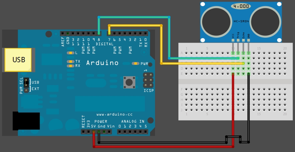
     The above sketch was created using Fritzing.


Arduino Code:
You can download the Arduino IDE from this site.

 1
2
3
4
5
6
7
8
9
10
11
12
13
14
15
16
17
18
19
20
21
22
23
24
25
26
27
28
29
30
31
32
33
34
35
36
37
38
39
40
41
42
43
44
45
46
47
48
49
50
51
52
53
54
55
56
57
58
59
60
/*
HC-SR04 Ping distance sensor:
VCC to arduino 5v
GND to arduino GND
Echo to Arduino pin 7
Trig to Arduino pin 8

This sketch originates from Virtualmix: http://goo.gl/kJ8Gl
Has been modified by Winkle ink here: http://winkleink.blogspot.com.au/2012/05/arduino-hc-sr04-ultrasonic-distance.html
And modified further by ScottC here: http://arduinobasics.blogspot.com.au/2012/11/arduinobasics-hc-sr04-ultrasonic-sensor.html
on 10 Nov 2012.
*/


#define echoPin 7 // Echo Pin
#define trigPin 8 // Trigger Pin
#define LEDPin 13 // Onboard LED

int maximumRange = 200; // Maximum range needed
int minimumRange = 0; // Minimum range needed
long duration, distance; // Duration used to calculate distance

void setup() {
Serial.begin (9600);
pinMode(trigPin, OUTPUT);
pinMode(echoPin, INPUT);
pinMode(LEDPin, OUTPUT); // Use LED indicator (if required)
}

void loop() {
/* The following trigPin/echoPin cycle is used to determine the
distance of the nearest object by bouncing soundwaves off of it. */
digitalWrite(trigPin, LOW);
delayMicroseconds(2);

digitalWrite(trigPin, HIGH);
delayMicroseconds(10);

digitalWrite(trigPin, LOW);
duration = pulseIn(echoPin, HIGH);

//Calculate the distance (in cm) based on the speed of sound.
distance = duration/58.2;

if (distance >= maximumRange || distance <= minimumRange){
/* Send a negative number to computer and Turn LED ON
to indicate "out of range" */
Serial.println("-1");
digitalWrite(LEDPin, HIGH);
}
else {
/* Send the distance to the computer using Serial protocol, and
turn LED OFF to indicate successful reading. */
Serial.println(distance);
digitalWrite(LEDPin, LOW);
}

//Delay 50ms before next reading.
delay(50);
}

The code above was formatted using hilite.me


Processing Code:
You can download the Processing IDE from this site.

 1
2
3
4
5
6
7
8
9
10
11
12
13
14
15
16
17
18
19
20
21
22
23
24
25
26
27
28
29
30
31
32
33
34
35
36
37
38
39
40
41
42
43
44
45
46
47
48
49
50
51
52
53
54
55
56
57
58
59
60
61
62
63
64
65
66
67
68
69
70
71
72
73
74
75
76
77
78
79
80
81
82
83
84
85
86
87
88
89
90
91
92
93
94
95
96
97
98
99
100
101
102
103
104
105
106
107
108
109
110
111
112
113
114
115
116
117
118
119
120
121
122
123
124
125
126
127
128
/* The following Processing Sketch was created by ScottC on
the 10 Nov 2012 : http://arduinobasics.blogspot.com/

Inspired by this Processing sketch by Daniel Shiffman:
http://processing.org/learning/basics/sinewave.html

*/
import processing.serial.*;


int numOfShapes = 60; // Number of squares to display on screen
int shapeSpeed = 2; // Speed at which the shapes move to new position
// 2 = Fastest, Larger numbers are slower

//Global Variables
Square[] mySquares = new Square[numOfShapes];
int shapeSize, distance;
String comPortString;
Serial myPort;

/* -----------------------Setup ---------------------------*/
void setup(){
size(displayWidth,displayHeight); //Use entire screen size.
smooth(); // draws all shapes with smooth edges.

/* Calculate the size of the squares and initialise the Squares array */
shapeSize = (width/numOfShapes);
for(int i = 0; i<numOfShapes; i++){
mySquares[i]=new Square(int(shapeSize*i),height-40);
}

/*Open the serial port for communication with the Arduino
Make sure the COM port is correct - I am using COM port 8 */
myPort = new Serial(this, "COM8", 9600);
myPort.bufferUntil('\n'); // Trigger a SerialEvent on new line
}

/* ------------------------Draw -----------------------------*/
void draw(){
background(0); //Make the background BLACK
delay(50); //Delay used to refresh screen
drawSquares(); //Draw the pattern of squares
}


/* ---------------------serialEvent ---------------------------*/
void serialEvent(Serial cPort){
comPortString = cPort.readStringUntil('\n');
if(comPortString != null) {
comPortString=trim(comPortString);

/* Use the distance received by the Arduino to modify the y position
of the first square (others will follow). Should match the
code settings on the Arduino. In this case 200 is the maximum
distance expected. The distance is then mapped to a value
between 1 and the height of your screen */
distance = int(map(Integer.parseInt(comPortString),1,200,1,height));
if(distance<0){
/*If computer receives a negative number (-1), then the
sensor is reporting an "out of range" error. Convert all
of these to a distance of 0. */
distance = 0;
}
}
}


/* ---------------------drawSquares ---------------------------*/
void drawSquares(){
int oldY, newY, targetY, redVal, blueVal;

/* Set the Y position of the 1st square based on
sensor value received */
mySquares[0].setY((height-shapeSize)-distance);

/* Update the position and colour of each of the squares */
for(int i = numOfShapes-1; i>0; i--){
/* Use the previous square's position as a target */
targetY=mySquares[i-1].getY();
oldY=mySquares[i].getY();

if(abs(oldY-targetY)<2){
newY=targetY; //This helps to line them up
}else{
//calculate the new position of the square
newY=oldY-((oldY-targetY)/shapeSpeed);
}
//Set the new position of the square
mySquares[i].setY(newY);

/*Calculate the colour of the square based on its
position on the screen */
blueVal = int(map(newY,0,height,0,255));
redVal = 255-blueVal;
fill(redVal,0,blueVal);

/* Draw the square on the screen */
rect(mySquares[i].getX(), mySquares[i].getY(),shapeSize,shapeSize);
}
}

/* ---------------------sketchFullScreen---------------------------*/
// This puts processing into Full Screen Mode
boolean sketchFullScreen() {
return true;
}

/* ---------------------CLASS: Square ---------------------------*/
class Square{
int xPosition, yPosition;

Square(int xPos, int yPos){
xPosition = xPos;
yPosition = yPos;
}

int getX(){
return xPosition;
}

int getY(){
return yPosition;
}

void setY(int yPos){
yPosition = yPos;
}
}

The code above was formatted using hilite.me


If you like this page, please do me a favour and show your appreciation :

  Visit my ArduinoBasics Google + page.
Follow me on Twitter by looking for ScottC @ArduinoBasics.
Have a look at my videos on my YouTube channel.


However, if you do not have a google profile...
Feel free to share this page with your friends in any way you see fit.

ADXL345 graphing program in Processing

OK, so I got this nice little sensor, the ADXL345 and I have composed it into a new version of my "shield".


read more

Let's Make Robots 11 Oct 18:25
adxl345  arduino  processing  uno  

An Arduino-enhanced espresso machine: the “Naked Espresso”

Reborn is an australian digital creative agency whose mission is to design smart and innovative ideas.
Among their works, a very nice one regards a hack consisting in the re-engineering of a sofisticated espresso machine, to show its peculiar features in the process of coffee making.
By means of an Arduino board, the team can collect real-time information such as flow rate, temperature and pressure; then, a Processing sketch graphically presents this data to the user in an artistic fashion.
Finally, each cup of coffee made this way is decorated with an artwork summarizing this information in its own “personal identity”.
More information can be found here.

[Via: The Naked Espresso]

Build a Touchless 3D Tracking Interface with Everyday Materials


Combine low-tech materials with some high-tech components and build a completely Touchless 3D Tracking Interface. Explore capacitive sensing by using several panels of cardboard lined with aluminum foil. These panels, when charged, create electric fields that correspond to X, Y, and Z axes to create a 3D cube. With the aid of an Arduino microcontroller and some supplied code, movements inside the cube are tracked as your hand moves around inside the field.

For Weekend Projects makers looking for an introduction to Arduino, this is a great project to learn from. Once you’ve gathered all your parts, this project should only take a couple hours to complete – you’ll be playing 3D Tic Tac Toe before the weekend is over!

Once your touchless 3D tracker is up and running, what you do with it is only limited by your own imagination! The original implementation of this project comes from media artist Kyle McDonald, who has suggested the following uses and applications:

  • Make an RGB or HSB color picker
  • Control video or music parameters; sequence a beat or melody
  • Large, slightly bent surface with multiple plates + a projector = “Minority Report” interface

Sign up below for the Weekend Projects Newsletter to receive the projects before anybody else does, get tips, see other makers’ builds, and more.

Sign Up for the "Weekend Projects" Newsletter
-->-->
-->-->

More:
See all of the Weekend Projects posts


Filed under: Arduino, MAKE Projects, Weekend Projects

Simple Arduino Serial Communication (Part 2)

In Stages 1 to 5 , we experimented with the Serial Monitor on the Arduino IDE to transmit data to the Arduino and receive data from the Arduino. We performed simple Serial communication of data in both directions.

We then moved from transmitting a String of characters to the more difficult task of transmitting a double or a float.

Finally, we used the Serial monitor to receive sensor data from our Arduino, and played with a couple of Arduino functions.

We will now look at replacing the Serial Monitor with a much more exciting program such as "Processing" which is a free Open Source program that interfaces very easily with the Arduino. It can be downloaded here.

We will use a few processing scripts to bring our Arduino Sensor projects to life !


Stage 6: A simple Processing Sketch: BLINK


Arduino IDE vs Processing IDE


While the processing IDE looks very similar to the Arduino IDE, it is important that you realise that the Processing sketch will run on your computer, and NOT on the Arduino. In fact, you do not even need an Arduino to run a Processing sketch. And that is exactly what we are going to do: Run a Processing sketch without an Arduino.

Parts Required


  • A computer
  • Processing IDE

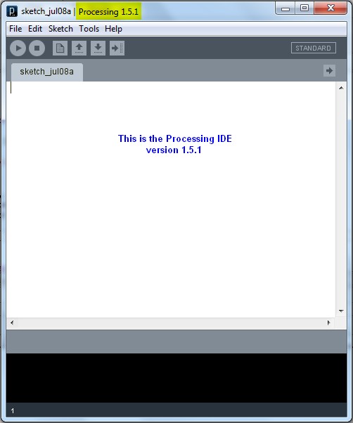
  • Once you have downloaded and installed the Processing IDE onto your computer, open the program and copy the following sketch into it, and then press the play button. This is different from the Arduino IDE, in that we do not have to upload it to anything, as it will be running from the computer.

    Processing Sketch


    1
    2
    3
    4
    5
    6
    7
    8
    9
    10
    11
    12
    13
    14
    15
    16
    17
    18
    19
    20
    21
    22
    23
    24
    25
    26
    27
    28
    29
    30
    31
    32
    33
    34
    35
    36
    37
    38
    39
    40
    41
    42

    /* Stage 6: Simple Processing Blink Sketch
    Created by ScottC on the 8/7/2012
    http://arduinobasics.blogspot.com/ */


    /* Setup the color variables and switching mechanism */
    color Red=color(255,0,0);
    color White=color(255,255,255);
    Boolean mySwitch=true;


    /* The setup function only runs once */

    void setup(){
    /* Set the size of the window using size(width,height) */
    size(400,400);
    }

    /* The draw function will refresh screen only after it has
    processed all functions within it. Which is why I needed
    a switch to swap between the red and the white background
    The draw() function will run in an endless loop. */

    void draw(){
    blink(mySwitch); //Call to blink function
    delay(2000); //The blinking speed (2 secs)
    }


    /* The blink function switches the background from red to white
    or from white to red. */

    void blink(Boolean swtch){
    /* If swtch is true, make the background red
    otherwise make it white */
    if(swtch){
    background(Red); // red
    }else {
    background(White); // white
    }
    /* Toggle mySwitch between true and false */
    mySwitch=!mySwitch;
    }


    Things to Try


    1. Change the White background to a black background

    2. Insert on line 9: color Black=color(0,0,0);
      Change line 38: background(Black);


    3. Increase the blink rate to 1 second

    4. Change line 25: delay(1000);
      WARNING : Do not increase the speed too much, it may cause an epileptic fit.


    Now that wasn't too hard I hope.
    And if you want a very good site to learn Processing have a look at these


  • The official Processing reference library
  • Official Processing Tutorials
  • Getting started with Processing
  • Daniel Shiffman's Processing Examples and Tutorials


  • Stage 7: Arduino and Processing Unite.


    So how do we get our Arduino to interface with our computer? Well, if the Serial Monitor on the Arduino IDE is not good enough, then you could use any program that is capable of Serial communication. Fortunately, Processing is one of those programs, but you could use C++, Java, Python, Microsoft Excel (using VBA), VB.Net, Gobetwino or some other programming language.

    Two programs will be created: One will be uploaded to the Arduino using the Arduino IDE, and the other will run on the computer. In this example we will use Processing as the program that will run on the computer.

    Enter the following sketch into the Arduino IDE and upload it to the Arduino. It serves to generate a random number between 0 and 400 every 200msec and will send it to the computer via the USB cable , using Serial communication.

    Arduino Sketch


     1
    2
    3
    4
    5
    6
    7
    8
    9
    10
    11
    12
    13
    /* Stage 7: Simple Arduino Serial Random Number Generator
    Written by ScottC on 09/07/2012
    http://arduinobasics.blogspot.com/
    */


    void setup(){
    Serial.begin(9600); //Begin Serial Communication
    }

    void loop(){
    Serial.println(random(1,1000)); //Send Random # to computer
    delay(200); //Delay 200ms between values.
    }


    Instructions

    Once the program has been uploaded to the Arduino, we will want to make sure that it is performing to expectations before moving onto the Processing script.

    Open the Arduino Serial Monitor and make sure that you see a bunch of random numbers scrolling down the page. If not, then go back over your code and try again. Once you see the random numbers, then it is safe to move on to the next step.


    Processing

    The following Processing script will display the Random numbers being sent from the Arduino in the Processing IDE debug window. This particular script is very much like a simplified Arduino Serial Monitor, and it will show you that the Processing Script is successfully communicating with the Arduino.


    Processing Sketch

     1
    2
    3
    4
    5
    6
    7
    8
    9
    10
    11
    12
    13
    14
    15
    16
    17
    18
    19
    20
    21
    22
    23
    24
    25
    26
    27
    28
    29
    30
    31
    32
    33
    34
    35
    36
    37
    38
    39
    40
    41
    42
    43
    44
    45
    46
    47
    48
    49
    50
    51
    52
    53
    54
    /* Some of the Serial code was adapted from Tom Igoe's example
    on this site: http://processing.org/reference/libraries/serial/Serial.html
    and http://processing.org/reference/libraries/serial/serialEvent_.html

    The rest of this Processing code was written by ScottC on 11/07/2012
    http://arduinobasics.blogspot.com/
    */


    import processing.serial.*; /* Needed for Serial Communication */

    /* Global variables */
    Serial comPort;
    String [] comPortList;
    String comPortString;

    /*--------------------------------------------------*/

    void setup(){
    size(100,100); /* Set the size of the window */
    background(0); /* Set the background to black */


    /* Get the available com ports. If there is at least one
    com port available, then start communicating on it.
    If there are more than one com ports available, we will
    only open the first one (i.e. comPortList[0])
    The bufferUntil('\n'); statement will generate a serial Event
    when it reads a carriage return */

    comPortList = Serial.list();
    if(comPortList.length>0){
    comPort = new Serial(this, comPortList[0], 9600);
    comPort.bufferUntil('\n');
    }
    }

    /*--------------------------------------------------*/

    void draw(){
    /* The serialEvent function will update the display */
    }

    /*--------------------------------------------------*/

    void serialEvent(Serial cPort){
    comPortString = cPort.readStringUntil('\n');
    if(comPortString != null) {
    comPortString=trim(comPortString);

    /* Print to the Debug screen in Processing IDE */
    println(comPortString);
    }
    }


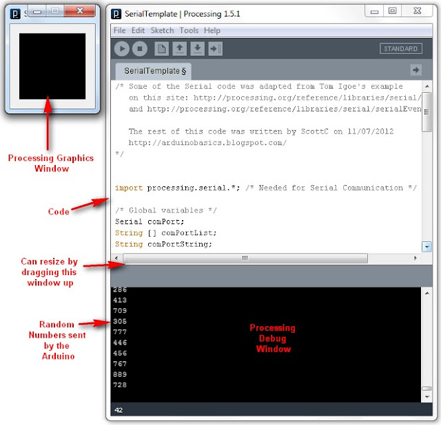
    When you run the Processing script, a little black window will appear. This is the Processing Graphics window, which is normally where all the action takes place. However in the sketch above, this window does nothing. Instead we make use of the black Debug window which is part of the Processing IDE (below the code window). If everything went to plan, you should see random numbers scrolling down in a similar fashion to the Arduino Serial monitor. Here is an example of what it should look like.


    Things to Try


    1. If you are having problems with COM port selection. Then have a look at the COM port being used on the Arduino IDE to upload sketches to the Arduino. Processing generally uses the same COM port. So make sure to close the Arduino Serial Monitor before running the Processing Sketches.


    The image above shows that I am currently using COM PORT 6 on my computer to upload Arduino Sketches. In the Processing sketch on line 32-35, I had this code:

    32
    33
    34
    35
      if(comPortList.length>0){
    comPort = new Serial(this, comPortList[0], 9600);
    comPort.bufferUntil('\n');
    }


    We can change line 33 to get Processing to use COM port 6 exclusively. We do this by replacing comPortList[0] with "COM6", as seen below:

    32
    33
    34
    35
      if(comPortList.length>0){
    comPort = new Serial(this, "COM6", 9600);
    comPort.bufferUntil('\n');
    }


    Stage 8 : Arduino and Processing - Random Font Project


    Arduino and Processing are speaking to each other by this stage, and we will keep our original Arduino Sketch to produce random numbers for us. Sure, we don't actually need the Arduino to do this for us, because Processing is more than capable of doing this itself, but we are building up towards an interactive sketch, so lets just go through the motions.

    Just in case your mouse scroll wheel doesn't move upwards, here is the Arduino Sketch again:

    Arduino Sketch


     1
    2
    3
    4
    5
    6
    7
    8
    9
    10
    11
    12
    13
    /* Stage 8: Simple Arduino Serial Random Number Generator
    Written by ScottC on 09/07/2012
    http://arduinobasics.blogspot.com/
    */


    void setup(){
    Serial.begin(9600); //Begin Serial Communication
    }

    void loop(){
    Serial.println(random(1,1000)); //Send Random # to computer
    delay(100); //Delay 100ms between values.
    }


    Upload the Arduino sketch to the Arduino, and then put the following code into the Processing IDE:

    Processing Sketch


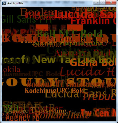
    The output of this sketch should look something like this:


    For stages 9 and above: Click Here


    Tasty Tweets

    Tasty Tweets is a data visualization experiment that allows users to explore twitter trends through taste with a press of a button. The installation has been developed by Kostantinos FrantzisRuben van der Vleuten and Kat Zorina during the Data Visualization course 2012 at Copenhagen Institute of Interaction Design,

    Using the Twitter APIs, the project collects tweets containing mentions of fruits such as blueberry, pineapple, apple and carrot and creates a smoothie.  The layering of the juices results in a visual representation of the proportions of flavors mentioned – a graph in a glass.

    Since twitter trends are changing very quickly, each smoothie has a unique palette of flavors.


    The Twitter APIs is used to gather the tweets while Processing is used to analyze and process the data and Arduino controls the flow of liquids into the glass with solenoids.

    More info here.


    @JarroseLaPlante Social Botanical Project

    @JarroseLaPlante is an installation created by Félicien Goguey and Thomas Meghe.

    This plant has a twitter account, you can water it by direct tweets. Since a single tweet can’t save her, she needs twitter friends to grow up!

    A Processing application listens to new tweets via Twitter APIs.  A servo motor is bringing water to the plant while sensor checks its the humidity rate (if it’s too low the plant tweets in order to alert her followers).

    If you follow the plant’s account,  she can send you private messages.

    Go here to visit the plant. And do not forget to water it!


    Triangle-grid LED display

    [Dearmash] put together this RGB LED display using triangles for each pixel. It’s an interesting deviation from the traditional grid layout. There are two video demos after the break. The first is a plasma-style pattern generated in Processing. The second is a spinning color wheel which would be perfect if synchronized with your Photoshop color spinner.

    So the physical build is done, and now [Dearmash] is looking for a purpose for the device (isn’t that always the way it happens?). He mentions that the triangular layout looks cool, but makes text display almost impossible. Does anyone have any ideas on how to make this work? Right off the bat we could see side-scrolling a font similar to the Metallica logo’s M and A. Bu there must be some way to group these pixels together into readable characters. If you always use an upward and downward pointed triangle on the same row as a pixel it makes a parallelogram which would be used to display italicization characters.


    Filed under: led hacks
    Hack a Day 31 May 14:01

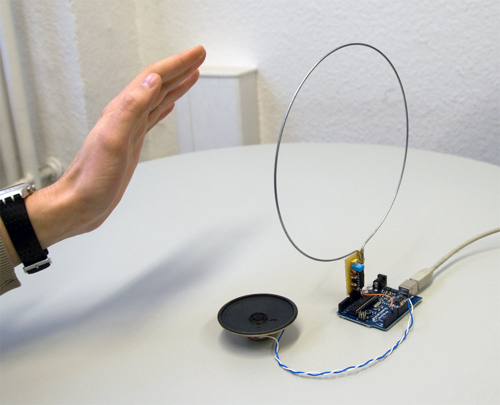
    Arduino-based theremin

    Theremin is one of the most exiting musical instruments ever made, mainly because of its “quite odd” playing method. Infact, its working principle is based on near-filed coupling between the hands of the theremin player and two metal antennas, used to determine the pitch of a variable-frequency oscillator and to adjust the volume of the output signal, respectively.
    Several theremin implementation are possible, such as the “original” analog one (based on the mixing of two sine waves originated by a fixed-frequency oscillator and a variable-frequency one) and those based on digital techniques.
    LabIII guys implemented a nice and simple Arduino theremin module, based on a TTL LC-type oscillator, usable not only to play electronic music, but also as a generic sensing-device, for example to control motors and/or to work with Processing, Max etc.
    The detailed description of the project, together with schematics and source code, can be found here.


    [Via: elektor.it]

    Arduino Blog 21 May 19:29

    Etch-a-Sketch 3.0 hands-on (video)

    The Etch-a-Sketch. A standard bearer for childhood, and one that most of us never really mastered. While Yelizaveta Lokshina can't help you create awe-inspiring portraits from aluminum powder, she has managed to update the toy for the digital age. Using an Arduino, a few buttons and a pressure sensor crammed inside a hollowed-out Etch-a-Sketch, the 3.0 version of the doodler is able to draw in old school gray, as well as vibrant colors created by blending an RGB palette. While holding down the red, green or blue button you squeeze the pressure sensor to add more or less of individual hues. The same sensor is used to change brush width when you hold down the black button. There's even a secret mode that automatically cycles through colors and thicknesses for creating vibrant, almost hallucinatory patterns.

    At the moment, the dual doodle knobs need to be physically connected to a computer so that a Processing script can work its magic and render the virtual Etch-a-Sketch. But, future versions may include wireless for sketching out images from the comfort of a couch and an accelerometer for the replicating the satisfying sensation of shaking the red fram to erase your creation. Basically, it's still a work in progress. Drawing with the Etch-a-Sketch 3.0 is just as satisfying, in a tactile sense, as the original, though we struggled slightly to get the hang of the pressure sensitive selector. One thing's for sure, though, the kids love it even more than the 1960 creation. Check out the video after the break to see it in action on the floor of the ITP Spring Show.

    Continue reading Etch-a-Sketch 3.0 hands-on (video)

    Etch-a-Sketch 3.0 hands-on (video) originally appeared on Engadget on Tue, 15 May 2012 20:21:00 EST. Please see our terms for use of feeds.

    Permalink | Email this | Comments