Posts with «photography» label

Simple Photo Flash Trigger for Water Balloon Photography

There have been countless projects to make custom photo flash trigger circuits. Usually the circuits react to sound, triggering the camera flash at the moment a certain sound is triggered. That type of trigger can be used to detect the popping of a balloon or shattering of glass. Other triggers detect motion, like a projectile crossing a laser beam for example. [Udo's] friend had a fun idea to take photos of water balloons popping. Unfortunately neither of those trigger methods would be well suited for this situation. That’s when [Udo] had to get creative.

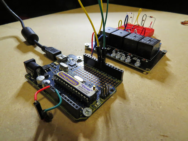
[Udo] built a unique trigger circuit that uses the water inside the balloon as the trigger. The core component of the circuit is an Arduino. One of the Arduino’s analog pins is configured to enable the internal pull-up resistor. If nothing else is connected to the pin, the Arduino will read 5 volts there. The pin is connected to a needle on the end of a stick. There is a second needle on the same stick, just a short distance away from the first. When these needles pierce the balloon’s skin, the water inside allows for a brief moment of conductivity between the two pins. The voltage on the analog pin then drops slightly, and the Arduino can detect that the balloon has popped.

[Udo] already had a flash controller circuit. He was able to trigger it with the Arduino by simply trying the flash controller’s trigger pin to one of the Arduino’s pins. If the Arduino pulls the pin to ground, it closes the switch on the flash controller and the flash is triggered. Both circuits must share a common ground in order for this to work.

All of the code for [Udo's] project is freely available. With such spectacular photographs, it’s only a matter of time before we see more of these floating around.


Filed under: Arduino Hacks
Hack a Day 02 Oct 21:00

Reverse Engineering a Wireless Studio Lighting Remote

If you want to take a photograph with a professional look, proper lighting is going to be critical. [Richard] has been using a commercial lighting solution in his studio. His Lencarta UltraPro 300 studio strobes provide adequate lighting and also have the ability to have various settings adjusted remotely. A single remote can control different lights setting each to its own parameters. [Richard] likes to automate as much as possible in his studio, so he thought that maybe he would be able to reverse engineer the remote control so he can more easily control his lighting.

[Richard] started by opening up the remote and taking a look at the radio circuitry. He discovered the circuit uses a nRF24L01+ chip. He had previously picked up a couple of these on eBay, so his first thought was to just promiscuously snoop on the communications over the air. Unfortunately the chips can only listen in on up to six addresses at a time, and with a 40-bit address, this approach may have taken a while.

Not one to give up easily, [Richard] chose a new method of attack. First, he knew that the radio chip communicates to a master microcontroller via SPI. Second, he knew that the radio chip had no built-in memory. Therefore, the microcontroller must save the address in its own memory and then send it to the radio chip via the SPI bus. [Richard] figured if he could snoop on the SPI bus, he could find the address of the remote. With that information, he would be able to build another radio circuit to listen in over the air.

Using an Open Logic Sniffer, [Richard] was able to capture some of the SPI communications. Then, using the datasheet as a reference, he was able to isolate the communications that stored information int the radio chip’s address register. This same technique was used to decipher the radio channel. There was a bit more trial and error involved, as [Richard] later discovered that there were a few other important registers. He also discovered that the remote changed the address when actually transmitting data, so he had to update his receiver code to reflect this.

The receiver was built using another nRF24L01+ chip and an Arduino. Once the address and other registers were configured properly, [Richard's] custom radio was able to pick up the radio commands being sent from the lighting remote. All [Richard] had to do at this point was press each button and record the communications data which resulted. The Arduino code for the receiver is available on the project page.

[Richard] took it an extra step and wrote his own library to talk to the flashes. He has made his library available on github for anyone who is interested.


Filed under: Arduino Hacks, radio hacks

Arduino Selfie


My attention is drawn towards the noise behind me....
I cannot believe it.
There it is.

  The Arduino is taking a SELFIE !!


How did this happen?
 
Well actually, it is not that difficult for an Arduino.
 
I found out that my Canon Powershot SX50 HS camera has a port on the side for a remote switch. In the "Optional Accessories" section of the camera brochure, it identifies the remote switch model as RS-60E3. I then looked up the model number on this website to find out the size of the jack (3 core, 2.5mm), and the pinout (Ground, focus and shutter) required to emulate the remote switch. Once I had this information, I was able to solder some really long wires to the jack and connect up the circuit (as described below).
 

And before I knew it, the Arduino was taking Selfies !!!


Warning : Any circuit you build for your camera (including this one) is at your own risk. I will not take responsibility for any damage caused to any of your equipment.
 

Parts Required:


Fritzing Sketch


Connection Table


Three core, 2.5 mm jack


Camera Connection to Relays


Jack pinout


Completed Circuit


Arduino Sketch


  1
2
3
4
5
6
7
8
9
10
11
12
13
14
15
16
17
18
19
20
21
22
23
24
25
26
27
28
29
30
31
32
33
34
35
36
37
38

/* ===============================================================
      Project: Arduino Selfie
       Author: Scott C
      Created: 14th Sept 2014
  Arduino IDE: 1.0.5
      Website: http://arduinobasics.blogspot.com/p/arduino-basics-projects-page.html
  Description: Arduino takes selfie every 30 seconds
================================================================== */

 /*
  Connect 5V on Arduino to VCC on Relay Module
  Connect GND on Arduino to GND on Relay Module */
 
 #define CH1 8   // Connect Digital Pin 8 on Arduino to CH1 on Relay Module
 #define CH3 7   // Connect Digital Pin 7 on Arduino to CH3 on Relay Module
 
 void setup(){
   //Setup all the Arduino Pins
   pinMode(CH1, OUTPUT);
   pinMode(CH3, OUTPUT);
   
   //Turn OFF any power to the Relay channels
   digitalWrite(CH1,LOW);
   digitalWrite(CH3,LOW);
   delay(2000); //Wait 2 seconds before starting sequence
 }
 
 void loop(){
   digitalWrite(CH1, HIGH); //Focus camera by switching Relay 1
   delay(2000);
   digitalWrite(CH1, LOW); //Stop focus
   delay(100);
   digitalWrite(CH3, HIGH); //Press shutter button for 0.5 seconds
   delay(500);
   digitalWrite(CH3,LOW); //Release shutter button
   delay(30000); //Wait 30 seconds before next selfie
 }


By connecting up the camera to an Arduino, the camera just got smarter !!
The Arduino connects to 2 different channels on the relay board in order to control the focus and the shutter of the camera. The relays are used to isolate the camera circuit from that of the Arduino. I have also included a couple of diodes and resistors in the circuit as an extra precaution, however they may not be needed.

Warning : Any circuit you build for your camera (including this one) is at your own risk. I will not take responsibility for any damage caused to any of your equipment. Do your research, and take any precautions you see fit.


The Video


If you like this page, please do me a favour and show your appreciation :

  Visit my ArduinoBasics Google + page.
Follow me on Twitter by looking for ScottC @ArduinoBasics.
Have a look at my videos on my YouTube channel.


However, if you do not have a google profile...
Feel free to share this page with your friends in any way you see fit.

When WiFi imitates art

For most of us, the only way we can see the strength of a WiFi network is by the familiar signal icon on any given device. Newcastle University School of Architecture doctorate student Luis Hernan, however, has a different method: spirit photography. He's using the new age-y method of capturing someone's aura via electric coronal discharges -- a Kirlian Device -- with a few geeky augmentations (an Arduino Uno board and WiFi Shield, for example) to illustrate how strong a wireless broadcast is with colors. As Wired notes, these components take account of the nearby signal and convert it into color information that's then beamed onto an LED strip; red being the strongest and blue being weaker sections of the network. To create the pictures like what you see above and at the source, Hernan swung the home-made device around after setting up long-exposure shots with a camera. While we can't know for sure, we'd imagine that something with no signal would look a lot like this.

Filed under: Wireless, Science, Alt

Comments

Via: Wired

Source: DigitalEthereal (1), (2)

Light Painting with a Thermal Flashlight

Impressed with the Public Laboratory's Thermal Flashlight prototype, maker Max Justicz whipped together a nice self-contained version using an infrared thermometer, some RGB LEDs, and an Arduino housed inside a commercial flashlight enclosure to perform a little DIY thermal imaging.
MAKE » Arduino 02 Jan 10:00

Phone Booth becomes a Photo Booth

A project by Chris Bell, Liangjie Xia, and Mike Kelberman called Rotobooth is a hacked rotary phone that takes your picture as you’re calling your own cell phone, then sends a link of the photos to you by SMS.

The rotary phone was hacked using Arduino, the photos were collected on a Flickr page, and finally the SMS notification is sent using Twilio. The exterior design is clean (dig the orange phone!) and recently took 3rd place at Twilio’s Photohack Day 2.

[via Twilio]

More:


Arduino Intervalometer

Here is to all the photography enthusiasts!

An intervalometer is a device that triggers signals in accurate time intervals and operates other devices. An interesting intervalometer using an Arduino is designed by Ken Murphy of Murphlabs .

This beautiful device is used to capture still images of a long time exposure kind.

Often the purpose of a photographic intervalometer is to reduce the resources required either to take the pictures or post-process them as similar images could be obtained by having the camera continuously take pictures as rapidly as possible. Using an intervalometer permits restricting the pictures taken to only those with the desired content. This reduces the requirements for resources such as power and storage media (e.g. film or memory card space).

It uses a really simple interface: you dial in the speed you want, referring to the blinking LEDs, and switch it into “go!” mode when you want it to start taking pictures.

He also has put up beautiful tutorials here. Can’t wait to see this one up!

[Via: Murphlab]

Arduino Blog 12 Mar 09:43