Posts with «photography» label

Control Your Camera Rig with the Blackmagic SDI Arduino Shield

Blackmagic's new 3G-SDI Arduino shield will make automating your camera and photography rig easier than ever with SDI input and output.

Read more on MAKE

The post Control Your Camera Rig with the Blackmagic SDI Arduino Shield appeared first on Make: DIY Projects and Ideas for Makers.

Shoot Super Detailed Macro Photographs with an RTI Camera Rig

Using many light sources, reflectance transformation imaging (RTI) is a method for photographing that allows you to get 3D map of surfaces.

Read more on MAKE

The post Shoot Super Detailed Macro Photographs with an RTI Camera Rig appeared first on Make: DIY Projects and Ideas for Makers.

Remote Treat Dispenser Sends You Adorable Photos of Your Pet

Need a quick mood lift when you're missing your pet? This treat dispensing camera rig will text you a photo of your pet.

Read more on MAKE

The post Remote Treat Dispenser Sends You Adorable Photos of Your Pet appeared first on Make: DIY Projects and Ideas for Makers.

You Can’t Touch This! Arduino Yún Alarm System

The purpose is clear. You don’t want your kids to steal your food from the cupboard, or from the fridge, or someone to open your locker. Or maybe you want to take pictures of your pet stealing food. Or maybe you are Dwight Schrute and you want to finally unmask […]

Read more on MAKE

The post You Can’t Touch This! Arduino Yún Alarm System appeared first on Make: DIY Projects, How-Tos, Electronics, Crafts and Ideas for Makers.

Robot on Rails for Time Lapse Photography

What do you get when you cross a photographer with an Arduino hacker? If the cross in question is [nukevoid], you wind up with a clever camera rail that can smoothly move with both shift and rotation capability. The impressive build uses an Arduino Pro Mini board and two stepper motors. One stepper moves the device on rails using some Delrin pulleys as wheels that roll on an extruded aluminum track. The other stepper rotates the camera platform.

The rotating platform is very cool. It’s a plastic disk with a GT2 motion belt affixed to the edge. The stepper motor has a matching pulley and can rotate the platform easily. The GT2 belt only goes around half of the disk, and presumably the software knows when to stop on either edge based on step counts. There’s even a support to steady the camera’s lens when in operation.

Some AA batteries provide power (so probably not going to run all day long without a battery change). Judging by the video, the whole set up is cat-resistant (although nothing is totally cat-proof). Photographers are an innovative bunch, and we’ve seen Android-powered rails before as well as spinning turntables.


Filed under: Arduino Hacks, robots hacks

New Project: Built a Motion Control Rig for Time-Lapse Photography

In this project, you'll learn how to use an Arduino microcontroller and a stepper motor to precisely control the panning of a camera during a time lapse.

Read more on MAKE

The post Built a Motion Control Rig for Time-Lapse Photography appeared first on Make: DIY Projects, How-Tos, Electronics, Crafts and Ideas for Makers.

Art Drops: capturing what the human eye can’t see


Art Drop is a project by italian photographer Gianluca Sambo and recently awarded with first prize from PX3, “Prix de la Photographie de Paris”. He’s been experimenting for some time a DIY technique based on Arduino to capture amazing shapes of liquid drops mixed with dyes and other ingredients to vary the density, and therefore, the shape of the liquid in motion. Arduino allows him to synchronise the camera with the flash and the water pump, creating a series of pictures full of colours and unforeseen shapes.

Take a look at the video below to see how it works:

Arduino Blog 25 Jun 23:22

A Single Pixel Digital Camera with Arduino

[Jordan] managed to cobble together his own version of a low resolution digital camera using just a few components. The image generated is pretty low resolution and is only in grey scale, but it’s pretty impressive what can be done with some basic hardware.

The heart of the camera is the image sensor. Most consumer digital cameras have tons of tiny receptors all jammed into the sensor. This allows for a larger resolution image, capturing more detail in a smaller space. Unfortunately this also usually means a higher price tag. [Jordan’s] sensor includes just a single pixel. The sensor is really just an infrared photodiode inside of a tube. The diode is connected to an analog input pin on an Arduino. The sensor can be pointed at an object, and the Arduino can sense the brightness of that one point.

In order to compile an actual image, [Jordan] needs to obtain readings of multiple points. Most cameras do this using the large array of pixels. Since [Jordan’s] camera only has a single pixel, he has to move it around and take each reading one at a time. To accomplish this, the Arduino is hooked up to two servo motors. This allows the sensor to be aimed horizontally and vertically. The Arduino slowly scans the sensor in a grid, taking readings along the way. A Processing application then takes each reading and compiles the final image.

Since this camera compiles an image so slowly, it sometimes has a problem with varying brightness. [Jordan] noticed this issue when clouds would pass over while he was taking an image. To fix this problem, he added an ambient light sensor. The Arduino can detect the amount of overall ambient light and then adjust each reading to compensate. He says it’s not perfect but the results are still an improvement. Maybe next time he can try it in color.


Filed under: Arduino Hacks

A Remote for CHDK Cameras Made Possible with Arduino

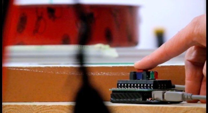
[AlxDroidDev] built himself a nice remote control box for CHDK-enabled cameras. If you haven’t heard of CHDK, it’s a pretty cool software modification for some Canon cameras. CHDK adds many new features to inexpensive cameras. In this case, [AlxDroidDev] is using a feature that allows the camera shutter to be activated via USB. CHDK can be run from the SD card, so no permanent modifications need to be made to the camera.

[AlxDroidDev’s] device runs off of an ATMega328p with Arduino. It operates from a 9V battery. The circuit contains an infrared receiver and also a Bluetooth module. This allows [AlxDroidDev] to control his camera using either method. The device interfaces to the camera using a standard USB connector and cable. It contains three LEDs, red, green, and blue. Each one indicates the status of a different function.

The Arduino uses Ken Shirrif’s IR Remote library to handle the infrared remote control functions. SoftwareSerial is used to connect to the Bluetooth module. The Arduino code has built-in functionality for both Canon and Nikon infrared remote controls. To control the camera via Bluetooth, [AlxDroidDev] built a custom Android application. The app can not only control the camera’s shutter, but it can also control the level of zoom.


Filed under: Arduino Hacks

DIY Canon Intervalometer using Arduino


An intervalometer allows you to take photos at set intervals to view a slow process in super fast speed. Watching paint dry is just as boring in fast motion as it is at normal speed, however, when you point your camera to the clouds in the sky, you can get some amazing effects.
 
By taking a picture every 3 seconds, and then playing the sequence back at 30 frames a second, you will get to see a 10 minute event in just 7 seconds.To get a nice flowing motion picture, you need to get a good balance between the recording frame rate, and the play-back frame rate.


The recording frame rate is limited by the amount of memory you have in your camera, the length of the captured event, battery charge, and the camera's general capabilities. The playback frame rate needs to be fast enough to prevent jittering, but not so fast that you lose the event in a blink of an eye. The more you practice with different subject matters, the more you get a feel for how long you need to keep the camera running and how long to leave between shots.
 
When taking pictures of the clouds, you can generally use a 3-5 second frame rate, depending on their speed across the sky. To capture the flow of traffic, I would recommend a picture every 1-2 seconds. However, for really slow events like a plant growing, you may need to extend the frame capture rate significantly. You will get a better idea once you try it for yourself.


This tutorial follows on from the Arduino selfie tutorial, so you might notice some similarities. However, in this tutorial, we will have more control over the intervalometer by using a sliding potentiometer and an LED bar. The pin layout is slightly different from the Arduino Selfie tutorial - so best to start from scratch to avoid pin misconfigurations.
 

Warning : Any circuit you build for your camera (including this one) is at your own risk. I will not take responsibility for any damage caused to any of your equipment.
 
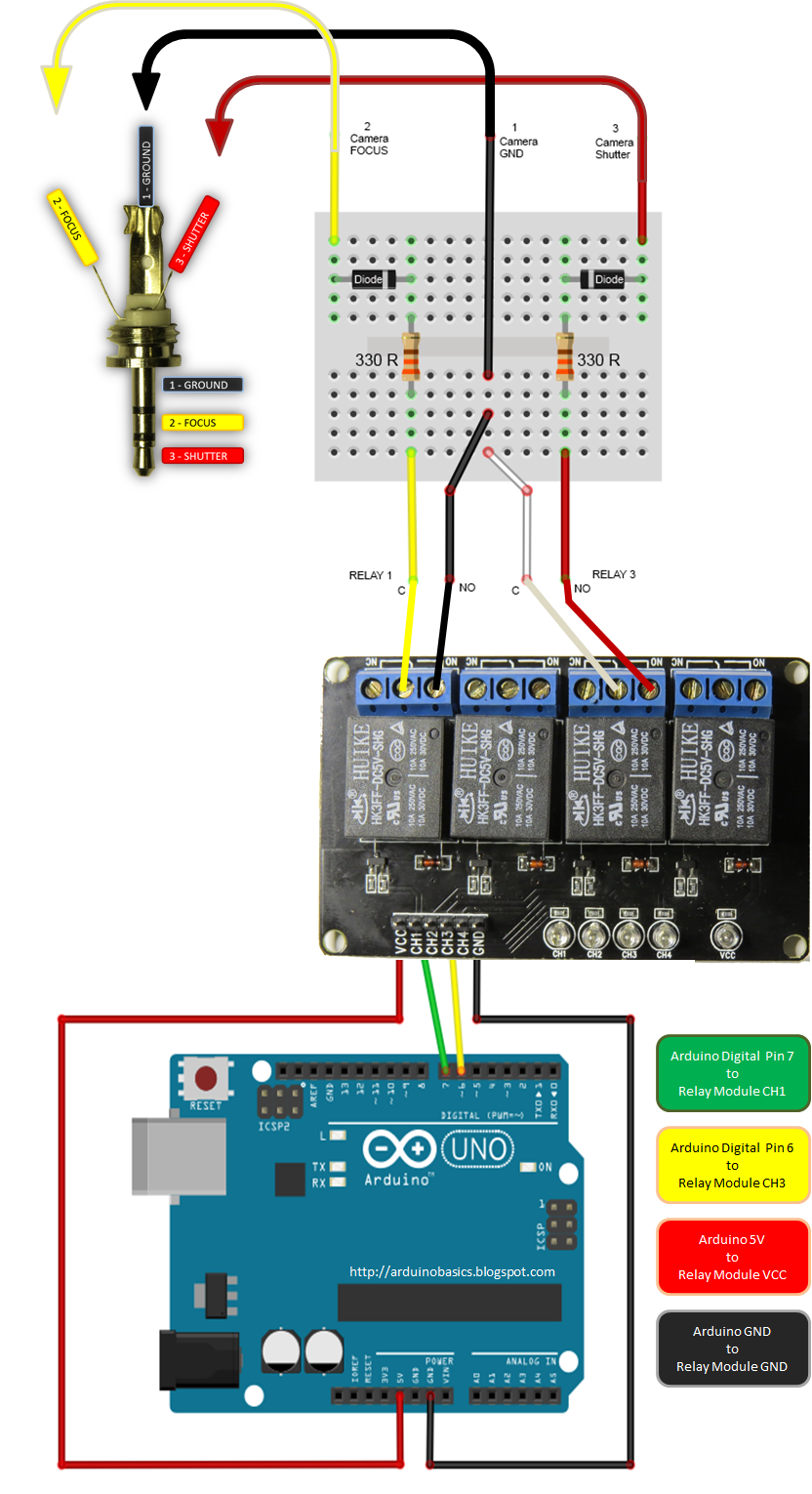
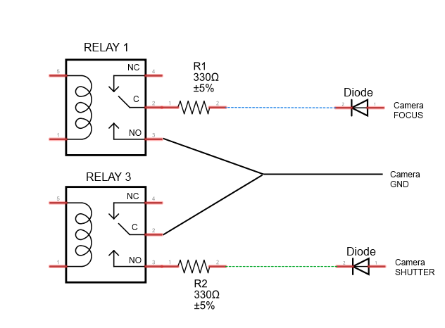
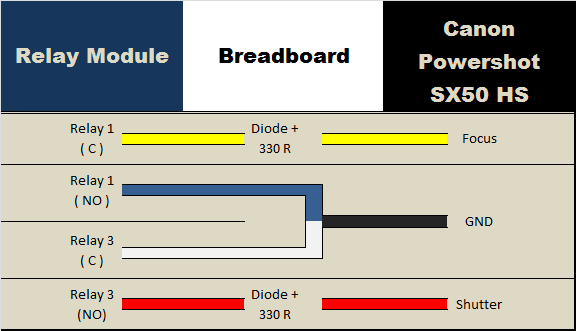
I found out that my Canon Powershot SX50 HS camera has a port on the side for a remote switch. In the "Optional Accessories" section of the camera brochure, it identifies the remote switch model as RS-60E3. I then looked up the model number on this website to find out the size of the jack (3 core, 2.5mm), and the pinout (Ground, focus and shutter) required to emulate the remote switch. Once I had this information, I was able to solder some really long wires to the jack and connect up the circuit (as described below).
 
I use Time-Lapse tool to stitch all of the pictures together to create a movie/animation.
 
You will need to download and install the LED_Bar library from Seeedstudio into your Arduino IDE libraries folder in order to use the LED Bar in this tutorial. For more information about the LED Bar - visit the LED Bar Seeed-Studio wiki.
 

Parts Required:


Fritzing Sketch


Connection Tables


Arduino to Relay Module:


Relay Module to Camera:


Arduino to Slide Potentiometer:


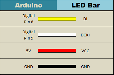
Arduino to LED Bar:


Arduino Sketch


  1
2
3
4
5
6
7
8
9
10
11
12
13
14
15
16
17
18
19
20
21
22
23
24
25
26
27
28
29
30
31
32
33
34
35
36
37
38
39
40
41
42
43
44
45
46
47
48
49
50
51
52
53
54
55
56
57
58
59
60
61
62
63
64
65
66
    
/* ===============================================================
      Project: DIY Canon Intervalometer using Arduino
       Author: Scott C
      Created: 9th October 2014
  Arduino IDE: 1.0.5
      Website: http://arduinobasics.blogspot.com/p/arduino-basics-projects-page.html
  Description: Use Arduino as an intervalometer for Canon PowerShot SX50 HS
               A slide potentiometer is used to control the time between photos.
               The LED Bar is used to display the delay between photos.
               A 3 core 2.5mm jack is used to connect the Arduino and Relay module to the Camera.
================================================================== */

 /* You will need to download and install the LED_Bar library from here: https://github.com/Seeed-Studio/Grove_LED_Bar */
 #include <LED_Bar.h>

 /* Connect 5V on Arduino to VCC on Relay Module
    Connect GND on Arduino to GND on Relay Module */

 #define CH1 7   // Connect Digital Pin 7 on Arduino to CH1 on Relay Module
 #define CH3 6   // Connect Digital Pin 6 on Arduino to CH3 on Relay Module
 
 int potPin=A0; //Connect Slide potentiometer to Analog Pin 0 on Grove Base Shield
 int potValue=0; //The variable used to hold the value of the potentiometer

 LED_Bar bar1(9,8); //Connect LED Bar to Digital I/O 8 on Grove base shield.
                   //The LED Bar actually uses digital pin 8 and 9.

 void setup(){
   pinMode(CH1, OUTPUT);
   pinMode(CH3, OUTPUT);
   
   //Turn OFF any power to the Relay channels
   digitalWrite(CH1,LOW);
   digitalWrite(CH3,LOW);
   delay(2000); //Wait 2 seconds before starting sequence
   
   //Focus camera by switching Relay 1
   digitalWrite(CH1, HIGH);
   delay(2000);
   digitalWrite(CH1, LOW); //Stop focus
   delay(3000);
 }

 void loop(){
      // Read the slide potentiometer and convert the reading to a value between 0 and 10.
      potValue=constrain(map(analogRead(potPin),0,1000,0,10),0,10);
      
      //Use the pot value to create a visual count-down display on the LED bar.
      for(int i = potValue; i>0; i--){
        bar1.setLevel(i);
        delay(1000);
      }
      
      //If the pot value is less than 1, then delay for 30 seconds.
      if(potValue<1){
        delay(30000);
      }
      
      //Turn LED Bar off when taking photo
      bar1.setLevelReverse(0);
      
      //Press shutter button for 0.1 seconds. Modify delay if required.
      digitalWrite(CH3, HIGH);
      delay(100);
      digitalWrite(CH3,LOW); //Release shutter button
 }


The Video


This project shows how to make your Canon Powershot SX50 HS a whole lot smarter using an Arduino. There are so many things that look so different with an intervalometer. While I connected a slide potentiometer to the Arduino to provide extra flexibility, and an LED Bar for visual feedback, there are many other sensors out there that can be combined with the camera. For example, you could use a PIR sensor to take a picture when movement is detected. Or take a picture when a laser trip-wire is broken. What about sound activation, light activation, leak detection.... the options are limitless.
 
This has been one of my favorite projects, it was a lot of fun, and very interesting.
I highly recommend that you try it out!


If you like this page, please do me a favour and show your appreciation :


Visit my ArduinoBasics Google + page.
Follow me on Twitter by looking for ScottC @ArduinoBasics.
Have a look at my videos on my YouTube channel.


However, if you do not have a google profile...
Feel free to share this page with your friends in any way you see fit.