Posts with «oled» label

OLED clock with Pacman mode

This large 2.42" OLED I2C module can be used as a replacement for the smaller 0.96" display for which I originally designed the ProMini OLED clock shield. It is built around the same SSD1306 chip, and it only comes in yellow (for now).

MikeM wrote this great Pacman clock sketch for it (available for download here), shown in the video below.


To display on the OLED, Mike used U8glib graphic library. Initially tested on the 0.96" OLED, the sketch froze after some time, for a yet to be explained reason. The same sketch works perfectly with the 2.42" display. Mike spent a lot of time trying to figure out if the culprit is software (bug in the U8glib) or hardware.
(Any feedback on this issue is greatly appreciated.)

The clock can also display the time as HH:MM:SS on the whole screen, as shown in the photo below, also courtesy of Mike.


My next step would be to design an enclosure for it. For that I will probably need some more help :)


Wise time with Arduino 24 Oct 02:41
i2c  oled  software  

A Better Google Glass For $60 (This One Folds)

For [Tony]‘s entry for The Hackaday Prize, he’s doing something we’ve all seen before – a head mounted display, connected to a Bluetooth module, displaying information from a smartphone. What we haven’t seen before is a cheap version of this tech, and a version of Google Glass that folds – you know, like every other pair of glasses on the planet – edges this project over from ‘interesting’ to ‘nearly practical’.

For the display, [Tony] is using a 0.96″ OLED connected to an Arduino Nano. This screen is directed into the wearer’s eye with a series of optics that, along with every other part of the frame, was 3D printed on a Solidoodle 2. The frame itself not only folds along the temples, but also along the bridge, making this HMD surprisingly compact when folded up.

Everything displayed on this head mounted display is controlled by  either an Android phone or a Bluetooth connection to a desktop. Using relatively simple display means [Tony] is limited to text and extremely simple graphics, but this is more than enough for some very interesting applications; reading SMS messages and checking email is easy, and doesn’t overpower the ‘duino.


The project featured in this post is an entry in The Hackaday Prize. Build something awesome and win a trip to space or hundreds of other prizes.


Filed under: 3d Printer hacks, wearable hacks

See what your Arduino is thinking with MicroView

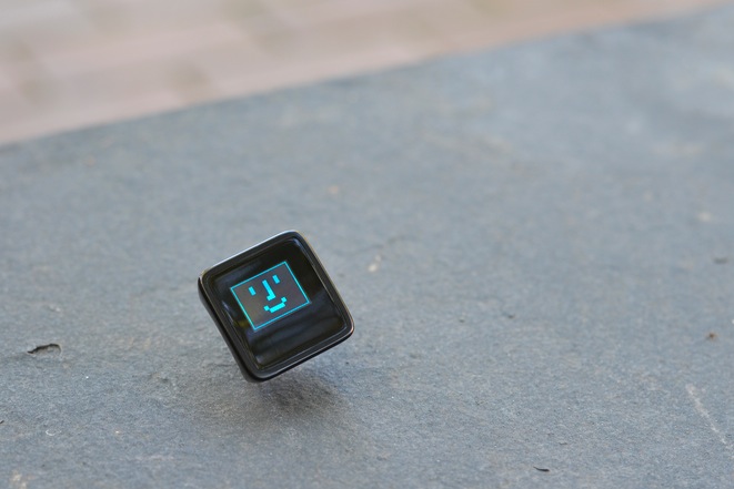
As some of you have already noticed on our social channels, we are thrilled to announce a new partner in the Arduino at Heart Program: MicroView, the first chip-sized Arduino compatible that lets you see what your Arduino is thinking using an OLED display.

Microview, by Geek Ammo, is versatile as it meets the needs of beginners and experts alike.

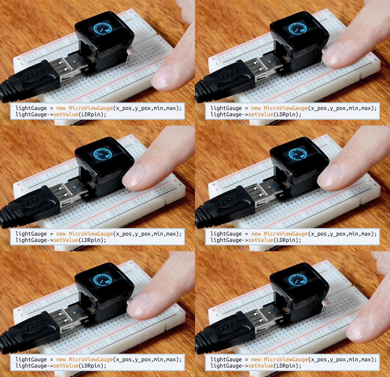
For beginners the MicroView is the first Arduino to ship with built in tutorials. Beyond the tutorials, the MicroView’s OLED display helps to visualize what the microcontroller is doing. You can print print debug messages straight to the OLED display without needing to connect to the Arduino IDE. The immediacy of being able to see live sensor values makes the whole experience so much easier.

A rich library saves experts time by allowing them to quickly display Strings, Counters, Gauges, Sliders, and Bitmaps with only a couple of lines of Arduino code.

Marcus Schappi, Geek Ammo CEO, told us:

“We’re proud that MicroView has been accepted to be part of the Arduino at Heart Program. By basing the MicroView on the architecture of the Arduino Uno, we’re standing on the shoulders of giants. We can’t wait to see what people make with the MicroView.”

Their Kickstarter campaign is really going well, but the campaign only has a few days left, so get in quick and back the MicroView now so you don’t miss out!


Review – Freetronics 128×128 Pixel Colour OLED Module

Introduction

Time for another review, and in this instalment we have the new 128×128 Pixel OLED Module from Freetronics. It’s been a while since we’ve had a full-colour graphic display to experiment with, and this one doesn’t disappoint. Unlike other displays such as LCD, this one uses OLED – “Organic Light-Emitting Diode” technology.

OLEDs allow for a faster refresh rate, and to the naked eye has a great amount of colour contrast. Furthermore the viewing angles are excellent, you can clearly read the display from almost any angle, for example:

However they can suffer from burn-in from extended display of the same thing so that does need to be taken into account. Nevertheless they provide an inexpensive and easy-to-use method of displaying colour text, graphics and even video from a variety of development boards. Finally – there is also a microSD socket for data logging, image storage or other uses. However back to the review unit. It arrives in typical retail packaging:

and includes the OLED display itself, a nifty reusable parts tray/storage box, and two buttons. The display has a resolution of 128 x 128 pixels and has a square display area with a diagonal size of 38.1 mm. The unit itself is quite compact:

The display is easily mounted using the holes on the left and right-hand side of the display. The designers have also allowed space for an LED, current-limiting resistor and button on each side, for user input or gaming – perfect for the  included buttons. However this section of the PCB is also scored-off so you can remove them if required. Using the OLED isn’t difficult, and tutorials have been provided for both Arduino and Raspberry Pi users.

Using with Arduino

After installing the Arduino library, it’s a simple matter of running some jumper wires from the Arduino or compatible board to the display – explained in detail with the “Quickstart” guide. Normally I would would explain how to use the display myself, however in this instance a full guide has been published which explains how to display text of various colours, graphics, displaying images stored on a microSD card and more. Finally there’s some interesting demonstration sketches included with the library. For example, displaying large amounts of text:

… the variety of fonts available:

… and for those interested in monitoring changing data types, a very neat ECG-style of sketch:

… and the mandatory rotating cube from a Freetronics forum member:

Using with Raspberry Pi

For users of this popular single-board computer, there’s a great tutorial and some example videos available on the Freetronics website for your consideration, such as the following video clip playback:

Support

Along with the Arduino and Raspberry Pi tutorials, there’s also the Freetronics support forum where members have been experimenting with accelerated drivers, demonstrations and more.

Competition!

For a chance to win your own OLED display, send a postcard with your email address clearly printed on the back to:

OLED Competition, PO Box 5435 Clayton 3168 Australia. 

Cards must be received by 24/10/2013. One card will then be selected at random and the winner will be sent one Freetronics OLED Display. Prize will be delivered by Australia Post standard air mail. We’re not responsible for customs or import duties, VAT, GST, import duty, postage delays, non-delivery or whatever walls your country puts up against receiving inbound mail.

Conclusion

Compared to previous colour LCD units used in the past, OLED technology is a great improvement – and demonstrated very well with this unit. Furthermore you get the whole package – anyone call sell you a display, however Freetronics also have the support, tutorials, drivers and backup missing from other retailers. So if you need a colour display, check it out.

And for more detail, full-sized images from this article can be found on flickr. And if you’re interested in learning more about Arduino, or want to introduce someone else to the interesting world of Arduino – check out my book (now in a third printing!) “Arduino Workshop” from No Starch Press.

In the meanwhile have fun and keep checking into tronixstuff.com. Why not follow things on twitterGoogle+, subscribe  for email updates or RSS using the links on the right-hand column? And join our friendly Google Group – dedicated to the projects and related items on this website. Sign up – it’s free, helpful to each other –  and we can all learn something.

[Note – OLED display was a promotional consideration from Freetronics]

The post Review – Freetronics 128×128 Pixel Colour OLED Module appeared first on tronixstuff.

Flight Suit V3

The next version of the LED Flight Suit marches forward with WM, lots of headway on key components:
  • Three 16-channel, 12-bit pwm PCA9685 chips will operate MOSFET's to switch 48 LED strips.
  • Small sot23 smd MOSFETs (or these); the old ones (P16NF06's) were too overkill, too big. Overkill is still good but there's some math this time.
  • RC batteries for more power: peak 14.8V and 12A no problem, but will be <500mA most of the time.
  • Thinner, lighter LED strips with 120 LED's/m.
  • Arm-based remote control with a 1.3" OLED screen, dials/buttons/sliders/TBD.
    • The remote control will hopefully be a second Arduino-based system, a serial peripheral to the main suit system.
  • Multi-band audio analysis with MSGEQ7 or a separate Arduino FFT.
Most importantly WM is coding Arduino!  He already built a complete mode-switching, parameter-adjusting system with a figure diagram on-screen!  

We'll make the suits themselves-- the displays with LED strips-- when we have a working circuit and software: we don't know where everything's going yet.  So for a demo display I'm making a circuit board showing all 48 PCA9685 outputs on LED bars-- old school.  Here's the one I'm scrapping-- got too much rework:


and here's an MSGEQ7's output, from iphone audio, of seven values on a Sure Electronics 24x16 panel:


That display will also help when debugging and building the system.
Jeff's Arduino Blog 11 May 20:17

Grove OLED 96x96 Slideshow

This project makes use of the Grove OLED 96x96 display to present a mini-slideshow.  Pictures on your computer are transferred to the OLED via a Processing script, and will cycle through them as many times as you choose.

Video:


Parts required:


Software required:


Sketch:


Arduino Sketch:
 1
2
3
4
5
6
7
8
9
10
11
12
13
14
15
16
17
18
19
20
21
22
23
24
25
26
27
28
29
30
31
32
33
34
35
36
37
38
39
40
41
42
43
44
45
46
47
48
49
50
51
52
53
54
55
56
57
58
59
60
61
62
63
// OLED Slideshow: Arduino Sketch written by ScottC 21/07/2012

#include <Wire.h>
#include <SeeedGrayOLED.h> //From http://garden.seeedstudio.com/images/c/c4/SeeedGrayOLED.zip
#include <avr/pgmspace.h>

int counter=0;

void setup()
{
//Allow communication to OLED
Wire.begin();

//Allow Serial communication between Freetronics Eleven and Computer
Serial.begin(28800);

//Initialise the OLED
SeeedGrayOled.init();
//Clear the OLED display
SeeedGrayOled.clearDisplay();
//Set to vertical mode - horizontal mode doesn't work with this example
SeeedGrayOled.setVerticalMode();

}

void loop(){
//Listen for Serial comunication
while (Serial.available()>0) {
// Read data and send directly to the OLED
sendMyData(Serial.read());
counter++;

//When counter reaches 4608 pixels, the picture is complete.
if(counter>4607){
//Insert delay to allow viewing of picture.
delay(4000);
Serial.println("End of Transmission");

//Reset the counter for the next picture
counter=0;
}
}
}

// This function was adapted from the SEEED Gray OLED driver so that
// character bytes could be sent directly to the OLED.
void sendMyData(unsigned char Data){
Wire.beginTransmission(SeeedGrayOLED_Address); // begin I2C transmission
Wire.send(SeeedGrayOLED_Data_Mode); // data mode
Wire.send(Data);
Wire.endTransmission();
}


// This function was adapted from the SEEED Gray OLED driver so that
// commands could be sent directly to the OLED.
// NOT USED IN THIS EXAMPLE ***********************
void sendMyCommand(unsigned char Cmd){
Wire.beginTransmission(SeeedGrayOLED_Address); // begin I2C communication
Wire.send(SeeedGrayOLED_Command_Mode); // Set OLED Command mode
Wire.send(Cmd);
Wire.endTransmission(); // End I2C communication
}


Processing Sketch:
  1
2
3
4
5
6
7
8
9
10
11
12
13
14
15
16
17
18
19
20
21
22
23
24
25
26
27
28
29
30
31
32
33
34
35
36
37
38
39
40
41
42
43
44
45
46
47
48
49
50
51
52
53
54
55
56
57
58
59
60
61
62
63
64
65
66
67
68
69
70
71
72
73
74
75
76
77
78
79
80
81
82
83
84
85
86
87
88
89
90
91
92
93
94
95
96
97
98
99
100
101
102
103
104
105
106
107
108
109
110
111
112
113
114
115
116
117
118
119
120
121
122
123
124
125
126
127
128
129
130
/* OLED Slideshow: Processing Sketch Written by ScottC 21/7/2012 

References:
Getting Pixels: http://www.learningprocessing.com/examples/chapter-15/example-15-7/
Greyscale conversion = http://www.openprocessing.org/sketch/60336
*/


import processing.serial.*; /* Needed for Serial Communication */

/* Global variables */
Serial comPort;
String [] comPortList;
String comPortString;
PImage img;
char[] tempGrey=new char[4609];
int startOffset=0;
ArrayList picNames;
int curLoop=1;
int totalPics=0;
int curPicNum=0;
boolean toggleSend=true;
boolean sendBouncer=true;

//Change maxLoops to a number > 1 if you want the pictures to loop.
int maxLoops=1;


void setup() {
//The size of the display is critical (must match the OLED)
size(96, 96);
//setup Serial
comPortList = Serial.list();
if(comPortList.length>0){
//baud rates greater than 28800 may produce unexpected results
comPort = new Serial(this, comPortList[0], 28800);
comPort.bufferUntil('\n');
} else{
println("NO COM PORTS AVAILABLE");
}

//Create an Array of pictures
picNames=new ArrayList();
picNames.add("Picture1.bmp");
picNames.add("Picture2.bmp");
picNames.add("Picture3.bmp");
picNames.add("Picture4.bmp");
// for more pictures just keep adding them to the list.
//The actual pictures must be located in the data folder of this project.
//Select Sketch/Add File to add the files to this folder.
//Make sure that the name of pictures match the names above.

//Get the total number of pictures added
totalPics=picNames.size();
}

void draw(){
if(toggleSend && sendBouncer){

// Debugging code: print("STARTED:");
// Debugging code: println(picNames.get(curPicNum));

sendImage((String)picNames.get(curPicNum)); //Send the picture to the OLED
toggleSend=false; //temporarily stop sending any more pictures until authorised
curPicNum++; //increment in preparation for the next picture

if(curPicNum==totalPics){
curPicNum=0; //go back to the first picture
curLoop++; //increment the loop counter
}
if(curLoop>maxLoops){
sendBouncer=false; //Stop any further looping
println("ANIMATION COMPLETE");
}
}
}


void sendImage(String imgName){
img = loadImage(imgName);
image(img,0,0,width,height);
loadPixels();
int counter=0;
for (int x = 0; x < width; x=x+2) {
for (int y = 0; y < height; y++) {
counter++;
int PixLoc = x + y*height; // this reads down then across2.
//Left pixel nibble
int Pix1=(round((red(pixels[PixLoc])*0.222+green(pixels[PixLoc])*0.707+blue(pixels[PixLoc])*0.071)))/16;
//Right pixel nibble
int Pix2=(round((red(pixels[PixLoc+1])*0.222+green(pixels[PixLoc+1])*0.707+blue(pixels[PixLoc+1])*0.071)))/16;
//Shift the byte <<4 for the left pixel nibble
int PixShift1=Pix1<<4;
//Combine both nibbles to form a byte
int PixFin = PixShift1+Pix2;
byte PixByteFin=byte(PixFin);
//Assign this byte to the tempGrey array
tempGrey[counter] = char(PixByteFin);
}
}
sendSerial(tempGrey); //Send the image data through the Serial COM Port/
}


//This function will send the byte/Char array to the Freetronics
//Eleven or Arduino.
void sendSerial(char[] Data){
for(int i=0; i<4608; i++){
//Needs an offset to get picture to align to screen properly
//only needs to do this once.
if(startOffset==0){
i=i+6;
startOffset++;
}
//Send the picture data to the Freetronics Eleven / Arduino
comPort.write(Data[i]);
}
}


//This function will wait for a response from the Freetronics
//Eleven or Arduino before sending any further pictures.
void serialEvent (Serial myPort) {
// get the ASCII string:
String inString = myPort.readStringUntil('\n');
if (inString != null) {
println(inString);
toggleSend=true; // Allow the next picture to be sent
}
}


Please note: that you must use the Arduino IDE version 023 until Seeed Studio update their driver for this OLED. Their current driver is not compatible with later versions of Arduino IDE.


OLED Lego train station emerges from Adafruit and Arduino gear, minifigs to get home on time

Who knew Lego characters had to be somewhere in a hurry? Adafruit did, as it just whipped up a minifig-sized train schedule. The invention mates one of Adafruit's own 1-inch OLED boards with an Arduino Uno controlling the schedule behind the scenes. It looks to be a straightforward project for the DIY types, although the display is currently all show: the schedule doesn't (yet) pair up with the train tracks to automatically let your minifigs know if their trip to the pirate spaceship castle has been delayed by ghosts. You can check the source link for the full instructions. Duplo builders, alas, are kept out of the loop.

OLED Lego train station emerges from Adafruit and Arduino gear, minifigs to get home on time originally appeared on Engadget on Tue, 26 Jun 2012 00:07:00 EST. Please see our terms for use of feeds.

Permalink | Email this | Comments