Posts with «motor» label

Giant Fog-Breathing Robotic Crow Shoots Lasers

Artist David Cranmer's "Stakcgrox" is a 3.5 meter tall robotic crow with a rotating head and glowing eyes that shoot lasers.

Read more on MAKE

The post Giant Fog-Breathing Robotic Crow Shoots Lasers appeared first on Make: DIY Projects, How-Tos, Electronics, Crafts and Ideas for Makers.

On Your Phone While Driving an Electric Skateboard

Skateboards are fun, but you have to do all that pesky kicking in order to get anywhere. That’s why [Nick] decided to build his own electric skateboard. Not only is the skateboard powered with an electric motor, but the whole thing can be controlled from a smart phone.

[Nick] started out with a long board deck that he had made years ago. After cleaning it up and re-finishing it, the board was ready for some wheels. [Nick] used a kit he found online that came with the trucks, wheels, and a belt. The trucks have a motor mount welded in place already. [Nick] used a Turnigy SK3 192KV electric motor to drive the wheels. He also used a Turnigy electronic speed controller to make sure he could vary the speed of the board while riding.

Next [Nick] needed some interface between a smart phone and the motor controller. He chose to use an Arduino Nano hooked up to a Bluetooth module. The Nano was able to directly drive the motor controller, and the Bluetooth module made it easy to sync up to a mobile phone. The Android app was written using MIT’s App Inventor software. It allows for basic control over the motor speed so you can cruise in style. Check out the video below for a slide show and some demonstration clips.

It’s a popular project, and eerily similar to the one we saw a couple months back.


Filed under: Arduino Hacks

A Single Pixel Digital Camera with Arduino

[Jordan] managed to cobble together his own version of a low resolution digital camera using just a few components. The image generated is pretty low resolution and is only in grey scale, but it’s pretty impressive what can be done with some basic hardware.

The heart of the camera is the image sensor. Most consumer digital cameras have tons of tiny receptors all jammed into the sensor. This allows for a larger resolution image, capturing more detail in a smaller space. Unfortunately this also usually means a higher price tag. [Jordan’s] sensor includes just a single pixel. The sensor is really just an infrared photodiode inside of a tube. The diode is connected to an analog input pin on an Arduino. The sensor can be pointed at an object, and the Arduino can sense the brightness of that one point.

In order to compile an actual image, [Jordan] needs to obtain readings of multiple points. Most cameras do this using the large array of pixels. Since [Jordan’s] camera only has a single pixel, he has to move it around and take each reading one at a time. To accomplish this, the Arduino is hooked up to two servo motors. This allows the sensor to be aimed horizontally and vertically. The Arduino slowly scans the sensor in a grid, taking readings along the way. A Processing application then takes each reading and compiles the final image.

Since this camera compiles an image so slowly, it sometimes has a problem with varying brightness. [Jordan] noticed this issue when clouds would pass over while he was taking an image. To fix this problem, he added an ambient light sensor. The Arduino can detect the amount of overall ambient light and then adjust each reading to compensate. He says it’s not perfect but the results are still an improvement. Maybe next time he can try it in color.


Filed under: Arduino Hacks

Pimp your ikea lamp into a customized death star

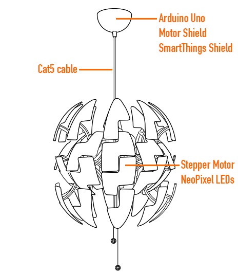
Ikea hacks are well widespread in the maker movement and David Bliss, founder at Nurun, did a great job transforming the Death Star inspired PS 2014 Pendant Lamp into something more dynamic.

The lamp was pimped up with an Arduino Uno and Arduino Motor Shield, NeoPixel LEDs and other components you can see in the illustration.

The detailed description of the project is on his blog , the code on github and the final result in the following video:

Arduino Blog 26 Nov 22:41
arduino  featured  ikea  led  motor  shield  

Tutorial – L298N Dual Motor Controller Modules and Arduino

Learn how to use inexpensive L298N motor control modules to drive DC and stepper motors with Arduino. This is chapter fifty-nine of our huge Arduino tutorial series.

You don’t have to spend a lot of money to control motors with an Arduino or compatible board. After some hunting around we found a neat motor control module based on the L298N H-bridge IC that can allows you to control the speed and direction of two DC motors, or control one bipolar stepper motor with ease.

The L298N H-bridge module can be used with motors that have a voltage of between 5 and 35V DC. With the module used in this tutorial, there is also an onboard 5V regulator, so if your supply voltage is up to 12V you can also source 5V from the board.

So let’s get started!

First we’ll run through the connections, then explain how to control DC motors then a stepper motor. At this point, review the connections on the L298N H-bridge module.

Consider the following image – match the numbers against the list below the image:

  1. DC motor 1 “+” or stepper motor A+
  2. DC motor 1 “-” or stepper motor A-
  3. 12V jumper – remove this if using a supply voltage greater than 12V DC. This enables power to the onboard 5V regulator
  4. Connect your motor supply voltage here, maximum of 35V DC. Remove 12V jumper if >12V DC
  5. GND
  6. 5V output if 12V jumper in place, ideal for powering your Arduino (etc)
  7. DC motor 1 enable jumper. Leave this in place when using a stepper motor. Connect to PWM output for DC motor speed control.
  8. IN1
  9. IN2
  10. IN3
  11. IN4
  12. DC motor 2 enable jumper. Leave this in place when using a stepper motor. Connect to PWM output for DC motor speed control.
  13. DC motor 2 “+” or stepper motor B+
  14. DC motor 2 “-” or stepper motor B-

Controlling DC Motors

To control one or two DC motors is quite easy with the L298N H-bridge module. First connect each motor to the A and B connections on the L298N module. If you’re using two motors for a robot (etc) ensure that the polarity of the motors is the same on both inputs. Otherwise you may need to swap them over when you set both motors to forward and one goes backwards!

Next, connect your power supply – the positive to pin 4 on the module and negative/GND to pin 5. If you supply is up to 12V you can leave in the 12V jumper (point 3 in the image above) and 5V will be available from pin 6 on the module. This can be fed to your Arduino’s 5V pin to power it from the motors’ power supply. Don’t forget to connect Arduino GND to pin 5 on the module as well to complete the circuit.

Now you will need six digital output pins on your Arduino, two of which need to be PWM (pulse-width modulation) pins. PWM pins are denoted by the tilde (“~”) next to the pin number, for example:

Finally, connect the Arduino digital output pins to the driver module. In our example we have two DC motors, so digital pins D9, D8, D7 and D6 will be connected to pins IN1, IN2, IN3 and IN4 respectively. Then connect D10 to module pin 7 (remove the jumper first) and D5 to module pin 12 (again, remove the jumper).

The motor direction is controlled by sending a HIGH or LOW signal to the drive for each motor (or channel). For example for motor one, a HIGH to IN1 and a LOW to IN2 will cause it to turn in one direction, and  a LOW and HIGH will cause it to turn in the other direction.

However the motors will not turn until a HIGH is set to the enable pin (7 for motor one, 12 for motor two). And they can be turned off with a LOW to the same pin(s). However if you need to control the speed of the motors, the PWM signal from the digital pin connected to the enable pin can take care of it.

This is what we’ve done with the DC motor demonstration sketch. Two DC motors and an Arduino Uno are connected as described above, along with an external power supply. Then enter and upload the following sketch:

// connect motor controller pins to Arduino digital pins
// motor one
int enA = 10;
int in1 = 9;
int in2 = 8;
// motor two
int enB = 5;
int in3 = 7;
int in4 = 6;
void setup()
{
  // set all the motor control pins to outputs
  pinMode(enA, OUTPUT);
  pinMode(enB, OUTPUT);
  pinMode(in1, OUTPUT);
  pinMode(in2, OUTPUT);
  pinMode(in3, OUTPUT);
  pinMode(in4, OUTPUT);
}
void demoOne()
{
  // this function will run the motors in both directions at a fixed speed
  // turn on motor A
  digitalWrite(in1, HIGH);
  digitalWrite(in2, LOW);
  // set speed to 200 out of possible range 0~255
  analogWrite(enA, 200);
  // turn on motor B
  digitalWrite(in3, HIGH);
  digitalWrite(in4, LOW);
  // set speed to 200 out of possible range 0~255
  analogWrite(enB, 200);
  delay(2000);
  // now change motor directions
  digitalWrite(in1, LOW);
  digitalWrite(in2, HIGH);  
  digitalWrite(in3, LOW);
  digitalWrite(in4, HIGH); 
  delay(2000);
  // now turn off motors
  digitalWrite(in1, LOW);
  digitalWrite(in2, LOW);  
  digitalWrite(in3, LOW);
  digitalWrite(in4, LOW);
}
void demoTwo()
{
  // this function will run the motors across the range of possible speeds
  // note that maximum speed is determined by the motor itself and the operating voltage
  // the PWM values sent by analogWrite() are fractions of the maximum speed possible 
  // by your hardware
  // turn on motors
  digitalWrite(in1, LOW);
  digitalWrite(in2, HIGH);  
  digitalWrite(in3, LOW);
  digitalWrite(in4, HIGH); 
  // accelerate from zero to maximum speed
  for (int i = 0; i < 256; i++)
  {
    analogWrite(enA, i);
    analogWrite(enB, i);
    delay(20);
  } 
  // decelerate from maximum speed to zero
  for (int i = 255; i >= 0; --i)
  {
    analogWrite(enA, i);
    analogWrite(enB, i);
    delay(20);
  } 
  // now turn off motors
  digitalWrite(in1, LOW);
  digitalWrite(in2, LOW);  
  digitalWrite(in3, LOW);
  digitalWrite(in4, LOW);  
}
void loop()
{
  demoOne();
  delay(1000);
  demoTwo();
  delay(1000);
}

So what’s happening in that sketch? In the function demoOne() we turn the motors on and run them at a PWM value of 200. This is not a speed value, instead power is applied for 200/255 of an amount of time at once.

Then after a moment the motors operate in the reverse direction (see how we changed the HIGHs and LOWs in thedigitalWrite() functions?).

To get an idea of the range of speed possible of your hardware, we run through the entire PWM range in the function demoTwo() which turns the motors on and them runs through PWM values zero to 255 and back to zero with the two for loops.

Finally this is demonstrated in the following video – using our well-worn tank chassis with two DC motors:

Controlling a Stepper Motor

Stepper motors may appear to be complex, but nothing could be further than the truth. In this example we control a typical NEMA-17 stepper motor that has four wires:

It has 200 steps per revolution, and can operate at at 60 RPM. If you don’t already have the step and speed value for your motor, find out now and you will need it for the sketch.

The key to successful stepper motor control is identifying the wires – that is which one is which. You will need to determine the A+, A-, B+ and B- wires. With our example motor these are red, green, yellow and blue. Now let’s get the wiring done.

Connect the A+, A-, B+ and B- wires from the stepper motor to the module connections 1, 2, 13 and 14 respectively. Place the jumpers included with the L298N module over the pairs at module points 7 and 12. Then connect the power supply as required to points 4 (positive) and 5 (negative/GND).

Once again if your stepper motor’s power supply is less than 12V, fit the jumper to the module at point 3 which gives you a neat 5V power supply for your Arduino.

Next, connect L298N module pins IN1, IN2, IN3 and IN4 to Arduino digital pins D8, D9, D10 and D11 respectively. Finally, connect Arduino GND to point 5 on the module, and Arduino 5V to point 6 if sourcing 5V from the module.

Controlling the stepper motor from your sketches is very simple, thanks to the Stepper Arduino library included with the Arduino IDE as standard.

To demonstrate your motor, simply load the stepper_oneRevolution sketch that is included with the Stepper library, for example:

Finally, check the value for

	const int stepsPerRevolution = 200;

in the sketch and change the 200 to the number of steps per revolution for your stepper motor, and also the speed which is preset to 60 RPM in the following line:

	myStepper.setSpeed(60);

Now you can save and upload the sketch, which will send your stepper motor around one revolution, then back again. This is achieved with the function

	myStepper.step(stepsPerRevolution); // for clockwise
	myStepper.step(-stepsPerRevolution); // for anti-clockwise

Finally, a quick demonstration of our test hardware is shown in the following video:

So there you have it, an easy an inexpensive way to control motors with your Arduino or compatible board. And if you enjoyed this article, or want to introduce someone else to the interesting world of Arduino – check out my book (now in a fourth printing!) “Arduino Workshop”.

Have fun and keep checking into tronixstuff.com. Why not follow things on twitterGoogle+, subscribe  for email updates or RSS using the links on the right-hand column, or join our forum – dedicated to the projects and related items on this website.

Tronixstuff 25 Nov 11:54

Tutorial – L298N Dual Motor Controller Modules and Arduino

Learn how to use inexpensive L298N motor control modules to drive DC and stepper motors with Arduino. This is chapter fifty-nine of our huge Arduino tutorial series.

You don’t have to spend a lot of money to control motors with an Arduino or compatible board. After some hunting around we found a neat motor control module based on the L298N H-bridge IC that can allows you to control the speed and direction of two DC motors, or control one bipolar stepper motor with ease.

The L298N H-bridge module can be used with motors that have a voltage of between 5 and 35V DC. With the module used in this tutorial, there is also an onboard 5V regulator, so if your supply voltage is up to 12V you can also source 5V from the board.

So let’s get started!

First we’ll run through the connections, then explain how to control DC motors then a stepper motor. At this point, review the connections on the L298N H-bridge module.

Consider the following image – match the numbers against the list below the image:

  1. DC motor 1 “+” or stepper motor A+
  2. DC motor 1 “-” or stepper motor A-
  3. 12V jumper – remove this if using a supply voltage greater than 12V DC. This enables power to the onboard 5V regulator
  4. Connect your motor supply voltage here, maximum of 35V DC. Remove 12V jumper if >12V DC
  5. GND
  6. 5V output if 12V jumper in place, ideal for powering your Arduino (etc)
  7. DC motor 1 enable jumper. Leave this in place when using a stepper motor. Connect to PWM output for DC motor speed control.
  8. IN1
  9. IN2
  10. IN3
  11. IN4
  12. DC motor 2 enable jumper. Leave this in place when using a stepper motor. Connect to PWM output for DC motor speed control.
  13. DC motor 2 “+” or stepper motor B+
  14. DC motor 2 “-” or stepper motor B-

Controlling DC Motors

To control one or two DC motors is quite easy with the L298N H-bridge module. First connect each motor to the A and B connections on the L298N module. If you’re using two motors for a robot (etc) ensure that the polarity of the motors is the same on both inputs. Otherwise you may need to swap them over when you set both motors to forward and one goes backwards!

Next, connect your power supply – the positive to pin 4 on the module and negative/GND to pin 5. If you supply is up to 12V you can leave in the 12V jumper (point 3 in the image above) and 5V will be available from pin 6 on the module. This can be fed to your Arduino’s 5V pin to power it from the motors’ power supply. Don’t forget to connect Arduino GND to pin 5 on the module as well to complete the circuit.

Now you will need six digital output pins on your Arduino, two of which need to be PWM (pulse-width modulation) pins. PWM pins are denoted by the tilde (“~”) next to the pin number, for example:

Finally, connect the Arduino digital output pins to the driver module. In our example we have two DC motors, so digital pins D9, D8, D7 and D6 will be connected to pins IN1, IN2, IN3 and IN4 respectively. Then connect D10 to module pin 7 (remove the jumper first) and D5 to module pin 12 (again, remove the jumper).

The motor direction is controlled by sending a HIGH or LOW signal to the drive for each motor (or channel). For example for motor one, a HIGH to IN1 and a LOW to IN2 will cause it to turn in one direction, and  a LOW and HIGH will cause it to turn in the other direction.

However the motors will not turn until a HIGH is set to the enable pin (7 for motor one, 12 for motor two). And they can be turned off with a LOW to the same pin(s). However if you need to control the speed of the motors, the PWM signal from the digital pin connected to the enable pin can take care of it.

This is what we’ve done with the DC motor demonstration sketch. Two DC motors and an Arduino Uno are connected as described above, along with an external power supply. Then enter and upload the following sketch:

// connect motor controller pins to Arduino digital pins
// motor one
int enA = 10;
int in1 = 9;
int in2 = 8;
// motor two
int enB = 5;
int in3 = 7;
int in4 = 6;
void setup()
{
  // set all the motor control pins to outputs
  pinMode(enA, OUTPUT);
  pinMode(enB, OUTPUT);
  pinMode(in1, OUTPUT);
  pinMode(in2, OUTPUT);
  pinMode(in3, OUTPUT);
  pinMode(in4, OUTPUT);
}
void demoOne()
{
  // this function will run the motors in both directions at a fixed speed
  // turn on motor A
  digitalWrite(in1, HIGH);
  digitalWrite(in2, LOW);
  // set speed to 200 out of possible range 0~255
  analogWrite(enA, 200);
  // turn on motor B
  digitalWrite(in3, HIGH);
  digitalWrite(in4, LOW);
  // set speed to 200 out of possible range 0~255
  analogWrite(enB, 200);
  delay(2000);
  // now change motor directions
  digitalWrite(in1, LOW);
  digitalWrite(in2, HIGH);  
  digitalWrite(in3, LOW);
  digitalWrite(in4, HIGH); 
  delay(2000);
  // now turn off motors
  digitalWrite(in1, LOW);
  digitalWrite(in2, LOW);  
  digitalWrite(in3, LOW);
  digitalWrite(in4, LOW);
}
void demoTwo()
{
  // this function will run the motors across the range of possible speeds
  // note that maximum speed is determined by the motor itself and the operating voltage
  // the PWM values sent by analogWrite() are fractions of the maximum speed possible 
  // by your hardware
  // turn on motors
  digitalWrite(in1, LOW);
  digitalWrite(in2, HIGH);  
  digitalWrite(in3, LOW);
  digitalWrite(in4, HIGH); 
  // accelerate from zero to maximum speed
  for (int i = 0; i &lt; 256; i++)
  {
    analogWrite(enA, i);
    analogWrite(enB, i);
    delay(20);
  } 
  // decelerate from maximum speed to zero
  for (int i = 255; i &gt;= 0; --i)
  {
    analogWrite(enA, i);
    analogWrite(enB, i);
    delay(20);
  } 
  // now turn off motors
  digitalWrite(in1, LOW);
  digitalWrite(in2, LOW);  
  digitalWrite(in3, LOW);
  digitalWrite(in4, LOW);  
}
void loop()
{
  demoOne();
  delay(1000);
  demoTwo();
  delay(1000);
}

So what’s happening in that sketch? In the function demoOne() we turn the motors on and run them at a PWM value of 200. This is not a speed value, instead power is applied for 200/255 of an amount of time at once.

Then after a moment the motors operate in the reverse direction (see how we changed the HIGHs and LOWs in thedigitalWrite() functions?).

To get an idea of the range of speed possible of your hardware, we run through the entire PWM range in the function demoTwo() which turns the motors on and them runs through PWM values zero to 255 and back to zero with the two for loops.

Finally this is demonstrated in the following video – using our well-worn tank chassis with two DC motors:

Controlling a Stepper Motor

Stepper motors may appear to be complex, but nothing could be further than the truth. In this example we control a typical NEMA-17 stepper motor that has four wires:

It has 200 steps per revolution, and can operate at at 60 RPM. If you don’t already have the step and speed value for your motor, find out now and you will need it for the sketch.

The key to successful stepper motor control is identifying the wires – that is which one is which. You will need to determine the A+, A-, B+ and B- wires. With our example motor these are red, green, yellow and blue. Now let’s get the wiring done.

Connect the A+, A-, B+ and B- wires from the stepper motor to the module connections 1, 2, 13 and 14 respectively. Place the jumpers included with the L298N module over the pairs at module points 7 and 12. Then connect the power supply as required to points 4 (positive) and 5 (negative/GND).

Once again if your stepper motor’s power supply is less than 12V, fit the jumper to the module at point 3 which gives you a neat 5V power supply for your Arduino.

Next, connect L298N module pins IN1, IN2, IN3 and IN4 to Arduino digital pins D8, D9, D10 and D11 respectively. Finally, connect Arduino GND to point 5 on the module, and Arduino 5V to point 6 if sourcing 5V from the module.

Controlling the stepper motor from your sketches is very simple, thanks to the Stepper Arduino library included with the Arduino IDE as standard.

To demonstrate your motor, simply load the stepper_oneRevolution sketch that is included with the Stepper library, for example:

Finally, check the value for

const int stepsPerRevolution = 200;

in the sketch and change the 200 to the number of steps per revolution for your stepper motor, and also the speed which is preset to 60 RPM in the following line:

myStepper.setSpeed(60);

Now you can save and upload the sketch, which will send your stepper motor around one revolution, then back again. This is achieved with the function

myStepper.step(stepsPerRevolution); // for clockwise
	myStepper.step(-stepsPerRevolution); // for anti-clockwise

Finally, a quick demonstration of our test hardware is shown in the following video:

So there you have it, an easy an inexpensive way to control motors with your Arduino or compatible board. And if you enjoyed this article, or want to introduce someone else to the interesting world of Arduino – check out my book (now in a fourth printing!) “Arduino Workshop”.

Have fun and keep checking into tronixstuff.com. Why not follow things on twitterGoogle+, subscribe  for email updates or RSS using the links on the right-hand column, or join our forum – dedicated to the projects and related items on this website.

The post Tutorial – L298N Dual Motor Controller Modules and Arduino appeared first on tronixstuff.

Tronixstuff 25 Nov 11:54

Control Large DC Motors with Arduino

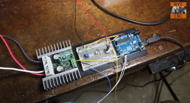
Arduino boards are able to control small motors very easily and it’s just as easy when you have to deal with controlling large motors. In the following video tutorial by NYC CNC you’ll see two examples. In the first you’ll learn how to get up and running, to start, stop, control direction and speed of a large motor with Arduino Uno. In the second example, how to use two proximity sensors as limit switches and two potentiometers to allow on-the-fly speed adjustment.

Arduino Blog 31 Oct 16:44

The world knows what you did last summer


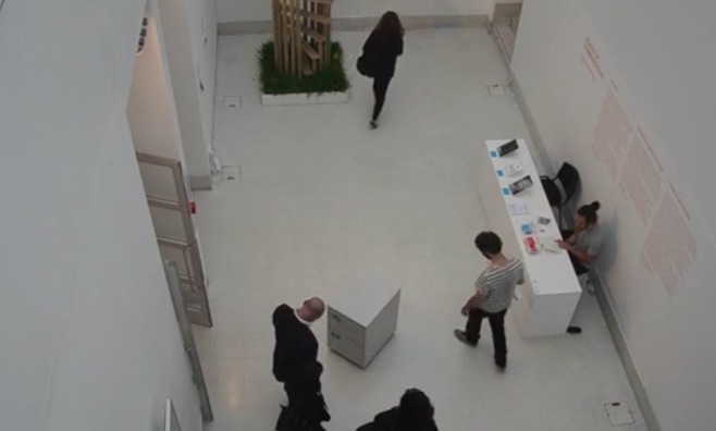
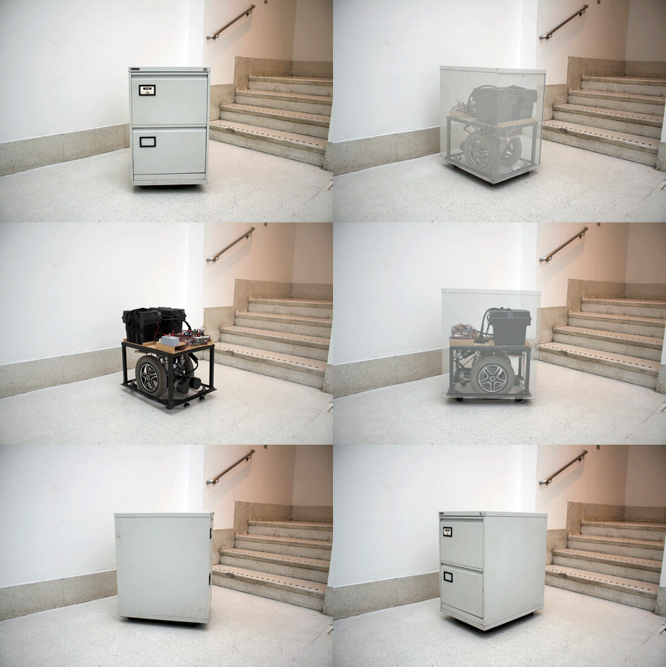
Jaap de Maat shared with us his final year project called I know what you did last summer, the finale to a two-year-long MA in Information Experience Design of the Royal College of Art. The ingredients are  simple (an old electric wheel chair, an Arduino Mega, 12v motor board, Bluetooth slave, wires, blood sweat and tears) and the concept is very actual:

It is physically impossible for the human brain to remember every event from our past in full detail. The default setting is to forget and our memories are constructed based on our current values. In the digital age it has become easier to look back with great accuracy. But this development contains hidden dangers, as those stored recollections can easily be misinterpreted and manipulated. That sobering thought should rule our online behaviour, because the traces we leave behind now will follow us around for ever.

The video of the installation shows how the physical presence of an archive drawer  stalking has a real impact on visitors:

Here’s the making of the prototype:

Arduino Blog 08 Jul 20:53

RoboRium - The Robot Emporium

RoboRium.com is an online robotics store by JMoon Technologies Pvt. Ltd. in India that offers a variety of products ranging from tools, electronic development boards, starter kits, microcontroller programmers, motors, mechanical kits and other hardware items related to robotics and home automation design, development & production which are acquired from international suppliers and delivered to customers at competitive prices.

read more

Let's Make Robots 29 Mar 12:53
arduino  kits  motor  robot  sensors  shops  

Sixteenth day: Arduino demo

Today’s class in the freshman design seminar went well. I started by returning the drafts of the design reports and giving some generic feedback. I realized on reading the reports that I had not given a good explanation of what I meant by describing the components of the system—two of the groups had given me long parts lists on the first page of their reports, something that would only really be appropriate in an appendix. I explained that what I wanted was what the main blocks in the block diagram were, and that they should use the block diagram to organize their report, writing a page for each block. I also suggested that they use the block diagram to partition the project among the group members, with each group member working on a different component, then getting back together to reconcile any discrepancies. Note that this is much more like real engineering group work than the usual K–12 group project, which is usually done most efficiently by turning the whole project over to the most competent member of the group.

After the feedback on design reports, I offered the students a chance to get a demo of building an Arduino program with sensing and motor control. This was a completely extemporaneous demo—I had gathered a number of possibly useful components, but had not tested anything ahead of time nor even figured out what order to do the demo in.  I asked the students if they wanted me to start with sensing or control—they asked for the motor control first.

I started by pulling a motor out of box of motors I had gotten when the elementary school my wife works at cleaned out their closets.  I told the students that I had no idea what the spec of the motor were, but since it came from an elementary school, it probably ran on 3v batteries.  I tested the motor by hooking it up first to the 3.3v, then to the 5v power on my Arduino Uno.  It spun just fine on 3.3v, but squealed a bit on 5v, so we decided to run it on 3.3v.

I then pulled out the Sainsmart 4-relay board that I had bought some time ago but never used.  I explained how a relay worked, what single-pole double-throw meant, and normally open (NO) and normally closed (NC) contacts. I used the board unpowered with the NC contacts to spin the motor, then moved the wire over to the NO contacts to turn the motor off.  I then hooked up power to the board and tried connecting input IN1 to power to activate the relay.  Nothing happened. I then tried connecting IN1 to ground, and the relay clicked and the motor spun.  The inputs to the Sainsmart board are active low, which I explained to the students (though I did not use the terminology “active low”—perhaps I should have).  I did make a point of establishing that the relay provides very good isolation between the control logic and the circuitry being controlled—you can hook up AC power from the walls to the relay contacts without interfering with the logic circuitry.

Having established that the relay worked, the next step was to get the class (as a group) to write an Arduino program to control the motor using the relay. With me taking notes on the whiteboard, they quickly came up with the pinMode command for the setup, the digitalWrite and delay for the loop, and with only a tiny bit of prompting with a second digitalWrite and delay to turn the motor back off.  They even realized the need to have different delays for the on and off, so we could tell whether we had the polarity right on the control.  Here is the program we came up with:

#define RELAY_PIN (3)

void setup()
{   pinMode(RELAY_PIN, OUTPUT);
}

void loop()
{
  digitalWrite(RELAY_PIN,LOW); // turn motor ON via relay (or off via transistor)
  delay(1000);  // on for 1 second
  digitalWrite(RELAY_PIN,HIGH); // turn motor OFF via relay (or on via transistor)
  delay(3000); // off for 3 seconds
}

I typed the code in and downloaded it to the Arduino Uno, and it worked as expected.  (It would be nice if the Arduino IDE would allow me to increase the font size, like almost every other program I use, so that students could have read the projection of what I was typing better.)

I then offered the students a choice of going on to sensing or looking at pulse-width modulation for proportional control.  They wanted PWM. I explained why PWM is not really doable with relays (the relays are too slow, and chattering them would wear them out after a while.  I did not have the specs on the relay handy, but I just looked up the specs for the SRD-05VDC-SL-C relays on the board: They have a mechanical life of 10,000,000 cycles, but an electrical life of only 100,000 cycles.  The relay takes about 7msec to make a contact and about 3msec to break a contact, so they can’t be operated much faster than about 60 times a second, which could wear them out in as little as half an hour.

So instead of a relay, I suggested an nFET (Field-Effect Transistor). I gave them a circuit with one side of the motor connected to 3.3V, the other to the drain of an nFET, with the source connected to ground.  I explained that the voltage between the gate and the source (VGS) controlled whether the transistor was on or off, and that putting 5v on the gate would turn it on fairly well. I then got out an AOI518 nFET and stuck it in my breadboard, explaining the orientation to allow using the other holes to connect to the source, gate, and drain.

I mentioned that different FETs have the order of the pins different, so one has to look up the pinout on data sheet. I pulled up the AOI518 data sheet, which has on the first page “RDS(ON) (at VGS = 4.5V) < 11.9mΩ”. I explained that if we were putting a whole amp through the FET (we’re not doing anywhere near that much current), the voltage drop would be 11.9mV, so the power dissipated in the transistor would be only 11.9mW, not enough to get it warm. I mentioned that more current would result in more power being dissipated (I2R), and that the FETs could get quite warm. I passed around my other breadboard which has six melted holes from FETs getting quite hot when I was trying to debug the class-D amplifier design. The students were surprised that the FETs still worked after getting that hot (I must admit that I was also).

I hooked up the AOI518 nFET using double-headed male header pins and female jumper cables, and the motor alternated on for 3 seconds, off for one second. We now had the transistor controlling the motor, so it was time to switch to PWM. I went to the Arduino reference page and looked around for PWM, finding it on analogWrite(). I clicked that link and we looked at the page, seeing that analog Write was like digitalWrite, except that we could put in a value from 0 to 255 that controlled what fraction of the time the pin was high.

I edited the code, changing the first digitalWrite() to analogWrite(nFET_GATE_PIN, 255), and commenting out the rest of the loop. We downloaded that, and it turned the motor on, as expected. I then tried writing 128, which still turned the motor on, but perhaps not as strongly (hard to tell with no load). Writing 50 resulted in the motor not starting. Writing 100 let the motor run if I started it by hand, but wouldn’t start the motor from a dead stop. I used this opportunity to point out that controlling the motor was not linear—1/5th didn’t run at 1/5th speed, but wouldn’t run the motor at all.

Next we switched over to doing sensors (with only 10 minutes left in the class). I got out the pressure sensor and instrumentation amp from the circuits course and hooked it up. The screwdriver I had packed in the box had too large a blade for the 0.1″ screw terminals, but luckily the tiny screwdriver on my Swiss Army knife (tucked away in the corkscrew) was small enough. After hooking up the pressure sensor to A0, I downloaded the Arduino Data Logger to the Uno, and started it from a terminal window. I set the triggering to every 100msec (which probably should be the default for the data logger), the input to A0, and convert to volts. I then demoed the pressure sensor by blowing into or sucking on the plastic tube hooked up to the sensor. With the low-gain output from the amplifier, the output swung about 0.5 v either way from the 2.5v center. Moving the A0 wire over to the high-gain output of the amplifier gave a more visible signal. I also turned off the “convert to volts” to show the students the values actually read by the Arduino (511 and 512, the middle of the range from 0 to 1023).

Because the class was over at that point, I offered to stay for another 10 minutes to show them how to use the pressure sensor to control the motor. One or two students had other classes to run to, but most stayed. I then wrote a program that would normally have the motor off, but would turn it full on if I got the pressure reading up to 512+255 and would turn it on partway (using PWM) between 512 and 512+255. I made several typos when entering the program (including messing up the braces and putting in an extraneous semicolon), but on the third compilation it downloaded successfully and controlled the motor as expected.

One student asked why the motor was off when I wasn’t blowing into the tube, so I explained about 512 being the pressure reading when nothing was happening (neither blowing into the tube nor sucking on it). I changed the zero point for the motor to a pressure reading of 300, so that the motor was normally most of the way on, but could be turned off by sucking on the tube. Here is the program we ended up with

#define nFET_GATE_PIN (3)

void setup()
{   pinMode(nFET_GATE_PIN, OUTPUT);
    pinMode(A0, INPUT);
}

void loop()
{ int pressure;
  pressure=analogRead(A0);
  if (pressure < 300)
  {    digitalWrite(nFET_GATE_PIN,LOW);  // turn motor off
  }
  else
  {   if (pressure>300+255)
      { digitalWrite(nFET_GATE_PIN,HIGH);  // turn motor on full
      }
      else
      {    analogWrite(nFET_GATE_PIN,pressure-300); // turn motor partway on
      }
  }
}

Note: this code is not an example of brilliant programming style. I can see several things that I would have done differently if I had had time to think about the code, but for this blog it is more useful to show the actual artifact that was developed in the demo, even if it makes me cringe a little.

Overall, I thought that the demo went well, despite being completely extemporaneous. Running over by 10 minutes might have been avoidable, but only by omitting something useful (like the feedback on the design reports). The demo itself lasted about 70 minutes, making the whole class run 80 minutes instead of 70. I think I compressed the demo about as much as was feasible for the level the students were at.

Based on how the students developed the first motor-control program quickly in class, I think that some of them are beginning to get some of the main ideas of programming: explicit instructions and sequential ordering. Because we were out of time by the point I got to using conditionals, I did not get a chance to probe their understanding there.


Filed under: freshman design seminar, Pressure gauge Tagged: Arduino, FET, motor, nMOS FET, pressure sensor, PWM, relay