Posts with «motor» label

Baby’s First Hands-Free Stroller

So you’ve had your first child. Congratulations; your life will never be the same again. [Dusan] was noticing how the introduction of his children into his life altered it by giving him less time for his hobbies in his home laboratory, and decided to incorporate his children into his hacks. The first one to roll out of his lab is a remote-controlled baby stroller.

After some engineering-style measurements (lots of rounding and estimating), [Dusan] found two motors to drive each of the back wheels on a custom stroller frame. He created a set of wooden gears to transfer power from the specialized motors to the wheels. After some batteries and an Arduino were installed, the stroller was ready to get on the road. At this point, though, [Dusan] had a problem. He had failed to consider the fact that children grow, and the added weight of the child was now too much for his stroller. After some adjustments were made (using a lighter stroller frame), the stroller was eventually able to push his kid around without any problems.

This is an interesting hack that we’re not sure has much utility other than the enjoyment that came from creating it. Although [Dusan]’s kid certainly seems to enjoy cruising around in it within a close distance to its operator. Be sure to check out the video of it in operation below, and don’t forget that babies are a great way to persuade your significant other that you need more tools in your work bench, like a CNC machine for example.


Filed under: wireless hacks

Arduino motor control problems!


Update 06/11/2016

Hey guys,

I sort of got the motor working. Adding a small resistance(about 2-3ohms) in series with the motor seemed to stop the Atmega reseting whenever Pin 3 was pulled HIGH (still don't know for sure what was causing this!). I'll still continue t troubleshoot this problem and completely figure out what exaclty was causing the Atmega to reset, since the resistor is not a permanent solution (wasteful energy loss). I'm really grateful for the huge amount of help from here guys!! Thanks alot! :)

Cheers!

read more

Let's Make Robots 26 Oct 12:06
arduino  avr  motor  noise  power supply  

Arduino motor control problems!

Hey guys,

I'm having trouble regarding motor control in a project I'm working on.

It uses an ATMega328 DIP package on a PCB. The motors I'm using are small coreless motors and I'm trying to control them using Si2302ds N-MOS FETs. For the power supply I'm using a 3.7V(4.2V on full charge) Lipo. I've tested this setup on a promini before and the motors turned on and off just fine.

read more

Let's Make Robots 26 Oct 12:06
arduino  avr  motor  noise  power supply  

Hackaday Prize Entry: The Green Machine

For Hackers, rapid prototyping is made easier using basic building blocks such as the Raspberry Pi, Arduino and the huge variety of add on shields for home brew projects. But we don’t see too many real world Industrial applications or machines built using these off-the-shelf electronics. [SlyScience] built The Green Machine – an industrial grade, automated spray painting device to help coat polycarbonate tubes consistently.

The Green Machine is essentially a linear drive that can move a spray gun across a spinning clear tube and coat it evenly with the desired color. These tubes are used as color filters – they slide over standard T5, T8 or T12 fluorescent lamps – and are used in advertising, special effects, films and similar applications. For almost 10 years prior to this machine, the task was done manually. The HPLV (high pressure, low volume) spray gun used for this process needed skilled hands to get consistent results. It was easy to ruin a tube and cleaning them was not possible. [SlyScience] figured things out on the go – teaching himself and figuring out all of the software and hardware pieces of the puzzle. The welded steel frame is about the only “custom” part in this build. Everything else is COTS. Check out the video of The Green Machine in action below, and if you have any tips to help improve the build, chime in with your comments.

The HackadayPrize2016 is Sponsored by:

Filed under: The Hackaday Prize

Arduino Stroboscope Animation


This tutorial will show you how to build your own Stroboscopic Animator using Magzor's Mechanotronic Design Portal as a starting point. Magzor Corporation is a business in California that is trying really hard to simplify robotic design. They want to enable users with little to no engineering experience to design and manufacture a custom robot by themselves in a matter of hours.

What is a stroboscope? A stroboscope is an instrument that uses a strobe light to make a moving object look stationary… We will use this feature to create an interesting 4 picture animation on a rotating disk.


Have a look at the video below to see the project in action, and the MDP process walk-through:


Video


Parts Required:


Magzor Schematic Diagram

Click to zoom ...
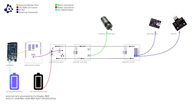
 

Further build instructions can be obtained by selecting the components in the Mechanotronics Design Portal within the Magzor website. Generating the build, and then selecting "Setup Instructions" tab at the top of the page. See video above to see this process in action.


Arduino Sketch


Make sure to copy and paste the following code into your Arduino IDE. It doesn't seem to work directly from the browser. You also need to install the Arduino Magzor I2C library ( http://magzor.com/downloads/ )


Putting it together


Arduino MEGA
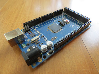


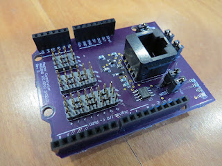
Magzor I2C board


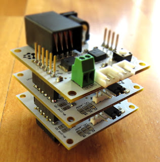
MIC Boards


MIC Boards Assembled


Sensors, Modules and Shields - all put together
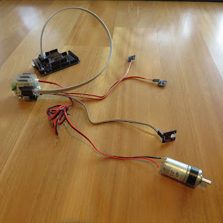


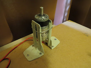
Motor with Bracket and Wire


Picture lined up with magnet on disk


Stroboscopic Animation
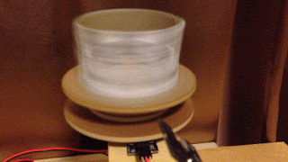


The Arduino MEGA microcontroller listens for the hall effect sensor to be triggered by the south facing side of the magnet on the underside of the rotating disk. As the magnet moves over the hall effect sensor, the sensor is triggered and the Arduino instructs the LED to blink for a fraction of a second. By manipulating the delay after the trigger time, we can get the LED to blink when one of the four images on the rotating disk is towards the front position. And if we get the timing right, we can make a simple animation.
 
If you watch the video above, you will see that the image bounces around a little bit. The duration of each frame is determined by the speed of the rotating disk (or motor), and the number of LED flashes per frame. Any changes in rotation speed will affect the position of the picture when the LED blinks. My rotating disk is not completely semetrical or centred correctly, and therefore a bit jumpy… but you get the idea. Bold images with high contrast seem to work best… Precision is key for this type of project. And if you can get the disk to rotate at a constant speed, you could probably do away with the hall effect sensors and magnets… however, in my case, these were essential in getting the project to work as intended.
 
This project is a lot of fun. You can really get creative by making your own pictures or 3 dimensional models (for a stop motion effect). Try different colours. It really is quite cool.


Concluding Comments


I would like to thank Magzor for supplying the components used in this tutorial, and letting me try out their MDP process. I really like the concept, the one stop shop which looks after you from beginning to end. Providing everything I needed to get the project off the ground. The point of this exercise was to go through the entire process of selecting the parts, build the project, and get it up and running. And I have done that in no time at all.
 
There is only one library to download and install, and the good thing is that you don't have to go hunting for it. The latest "correct" working version of the library is easy to find, right there on the Magzor website… Speaking of the Magzor website, please make sure to take a quick look around. It is quite impressive.


If you like this page, please do me a favour and show your appreciation :

 
Visit my ArduinoBasics Google + page.
Follow me on Twitter by looking for ScottC @ArduinoBasics.
I can also be found on Pinterest and Instagram.
Have a look at my videos on my YouTube channel.


This project would not have been possible without the collaborative effort from Magzor Corporation.
Please visit their site and check out the MDP.


However, if you do not have a google profile...
Feel free to share this page with your friends in any way you see fit.

Arduino Stroboscope Animation


UPDATE: Magzor has just started a Kickstarter campaign. Please check it out to get a good package deal on many of their components. Many of which were used in this tutorial.
 
This tutorial will show you how to build your own Stroboscopic Animator using Magzor's Mechanotronic Design Portal as a starting point. Magzor Corporation is a business in California that is trying really hard to simplify robotic design. They want to enable users with little to no engineering experience to design and manufacture a custom robot by themselves in a matter of hours.
What is a stroboscope? A stroboscope is an instrument that uses a strobe light to make a moving object look stationary… We will use this feature to create an interesting 4 picture animation on a rotating disk.


Have a look at the video below to see the project in action, and the MDP process walk-through:


Video


Parts Required:


Magzor Schematic Diagram

Click to zoom ...

 
Further build instructions can be obtained by selecting the components in the Mechanotronics Design Portal within the Magzor website. Generating the build, and then selecting "Setup Instructions" tab at the top of the page. See video above to see this process in action.


Arduino Sketch


Make sure to copy and paste the following code into your Arduino IDE. It doesn't seem to work directly from the browser. You also need to install the Arduino Magzor I2C library ( http://magzor.com/downloads/ )


Putting it together


Arduino MEGA


Magzor I2C board


MIC Boards


MIC Boards Assembled


Sensors, Modules and Shields - all put together


Motor with Bracket and Wire


Picture lined up with magnet on disk


Stroboscopic Animation


The Arduino MEGA microcontroller listens for the hall effect sensor to be triggered by the south facing side of the magnet on the underside of the rotating disk. As the magnet moves over the hall effect sensor, the sensor is triggered and the Arduino instructs the LED to blink for a fraction of a second. By manipulating the delay after the trigger time, we can get the LED to blink when one of the four images on the rotating disk is towards the front position. And if we get the timing right, we can make a simple animation.
 
If you watch the video above, you will see that the image bounces around a little bit. The duration of each frame is determined by the speed of the rotating disk (or motor), and the number of LED flashes per frame. Any changes in rotation speed will affect the position of the picture when the LED blinks. My rotating disk is not completely semetrical or centred correctly, and therefore a bit jumpy… but you get the idea. Bold images with high contrast seem to work best… Precision is key for this type of project. And if you can get the disk to rotate at a constant speed, you could probably do away with the hall effect sensors and magnets… however, in my case, these were essential in getting the project to work as intended.
 
This project is a lot of fun. You can really get creative by making your own pictures or 3 dimensional models (for a stop motion effect). Try different colours. It really is quite cool.


Concluding Comments


I would like to thank Magzor for supplying the components used in this tutorial, and letting me try out their MDP process. I really like the concept, the one stop shop which looks after you from beginning to end. Providing everything I needed to get the project off the ground. The point of this exercise was to go through the entire process of selecting the parts, build the project, and get it up and running. And I have done that in no time at all.
 
There is only one library to download and install, and the good thing is that you don't have to go hunting for it. The latest "correct" working version of the library is easy to find, right there on the Magzor website… Speaking of the Magzor website, please make sure to take a quick look around. It is quite impressive.
 
  UPDATE: Magzor has just started a Kickstarter campaign. Please check it out to get a good package deal on many of their components. Many of which were used in this tutorial.


If you like this page, please do me a favour and show your appreciation :

 
Visit my ArduinoBasics Google + page.
Follow me on Twitter by looking for ScottC @ArduinoBasics.
I can also be found on Pinterest and Instagram.
Have a look at my videos on my YouTube channel.


This project would not have been possible without the collaborative effort from Magzor Corporation.
Please visit their site and check out the MDP.


However, if you do not have a google profile...
Feel free to share this page with your friends in any way you see fit.

Home-Made Solenoid Motor

Want to really understand how something works? Make one yourself. That’s the approach that Reddit user [Oskarbjo] took with this neat electric motor build. He made the whole thing from scratch, using an Arduino, 3D printing, and ample quantities of wire to create a solenoid motor. This transforms the linear force of a solenoid, where a magnet is moved by a magnetic field, into rotary force. It’s rather like an internal combustion engine, but driven by electricity instead of explosions. Hopefully.

[Oskarbjo]’s engine seems to work, including a rather neat mechanism to detect the rotation of the shaft and relay that back to the controller. He hasn’t posted much detail in the build process, unfortunately, but did say that “If you’d want to build something similar I can probably help you out a bit, but half the fun is coming up with your own solutions.” Amen to that. We’ve seen a few neat solenoid motor builds, but this one wins points for starting from scratch. There is an Instagram video of the motor running after the break.


Filed under: Arduino Hacks

There Is No Spoon; Automatic Self Stirring Mug

Sometimes it’s helpful to realize the truth that there is no spoon. At least, not with [Ronaldo]’s automatic self-stirring mug. At first it was just a small propeller in the bottom of the mug that turned on by pushing a button in the handle, but this wasn’t as feature-rich as [Ronaldo] hoped it could be, so he decided to see just how deep the automatic beverage-mixing rabbit hole goes.

The first thing to do was to get a microcontroller installed to handle the operation of the motor. The ATtiny13a was perfect for the job since it’s only using one output pin to control the motor, and can be configured to only draw 0.5 microamps in power-saving mode. This ensures a long life for the two AAA batteries that power the microcontroller and the motor.

As far as operation goes, the motor operates in different modes depending on how many times the button in the handle is pushed. It can be on continuously or it can operate at pre-determined intervals for a certain amount of time, making sure to keep the beverage thoroughly mixed for as long as the power lasts. Be sure to check out the video below for a detailed explanation of all of the operating modes. We could certainly see some other possible uses for more interesting beverages as well.


Filed under: cooking hacks
Hack a Day 24 Jan 21:00