Posts with «linux» label

The Internet of Linux Things

The Linux Foundation is a non-profit organization that sponsors the work of Linus Torvalds. Supporting companies include HP, IBM, Intel, and a host of other large corporations. The foundation hosts several Linux-related projects. This month they announced Zephyr, an RTOS aimed at the Internet of Things.

The project stresses modularity, security, and the smallest possible footprint. Initial support includes:

  • Arduino 101
  • Arduino Due
  • Intel Galileo Gen 2
  • NXP FRDM-K64F Freedom

The project (hosted on its own Website) has downloads for the kernel and documentation. Unlike a “normal” Linux kernel, Zephyr builds the kernel with your code to create a monolithic image that runs in a single shared address space. The build system allows you to select what features you want and exclude those you don’t. You can also customize resource utilization of what you do include, and you define resources at compile time.

By default, there is minimal run-time error checking to keep the executable lean. However, there is an optional error-checking infrastructure you can include for debugging.

The API contains the things you expect from an RTOS like fibers (lightweight non-preemptive threads), tasks (preemptively scheduled), semaphores, mutexes, and plenty of messaging primitives. Also, there are common I/O calls for PWM, UARTs, general I/O, and more. The API is consistent across all platforms.

You can find out more about Zephyr in the video below. We’ve seen RTOS systems before, of course. There’s even some for robots. However, having a Linux-heritage RTOS that can target small boards like an Arduino Due and a Freedom board could be a real game changer for sophisticated projects that need an RTOS.


Filed under: Arduino Hacks, ARM, linux hacks, news
Hack a Day 25 Feb 16:30

Combining Musical Hatred with Target Practice

Not everyone can agree on what good music is, but in some cases you’ll find that just about everyone can agree on what is awful. That’s what the people over at Neo-Pangea discovered when they were listening to Internet radio. When one of those terrible songs hits their collective eardrums, the group’s rage increases and they just need to skip the track.

This is how Engineers act if the song is super-awful

Rather than use a web app or simple push button to do the trick, they turned the “skip” button into a NERF target. They call their creation the Boom Box Blaster and made a fantastic demo film video about it which is found after the break.

Inspired by a painting in the office, the target takes the form of a small hot air balloon. The target obviously needed some kind of sensor that can detect when it is hit by a NERF dart. The group tried several different sensor types, but eventually settled on a medium vibration sensor. This sensor is connected to an Arduino, which then communicates with a Raspberry Pi over a Serial connection. The Pi uses a Python script to monitor the Arduino’s vibration sensor. The system also includes some orange LEDs to simulate flames and a servo attached to the string which suspends the balloon from the ceiling. Whenever a hit is registered, the flames light up and the balloon raises into the air to indicate that the shot was on target.

The Pi was required in order to interface with the group’s streaming music service of choice; Sonos. The Sonos API made it easy for the team to interface their target with the “skip track” function. They just wrote a Node.js script that runs on the Pi and sends the proper command as necessary. Now whenever the radio asks the group if they want to build a snowman, they can all answer with a resounding, “no!”. They just need to make sure they have enough ammo to spare. Be sure to check out the comical demonstration video on the project page.


Filed under: Android Hacks, musical hacks

Bread Online is a Bread Maker for the Internet of Things

An engineering student at the University of Western Macedonia has just added another appliance to the ever-growing list of Internet enabled things. [Panagiotis] decided to modify an off-the-shelf bread maker to enable remote control via the Internet.

[Panagiotis] had to remove pretty much all of the original control circuitry for this device. The original controller was replaced with an Arduino Uno R3 and an Ethernet shield. The temperature sensor also needed to be replaced, since [Panagiotis] could not find any official documentation describing the specifications of the original. Luckily, the heating element and mixer motor were able to be re-used.

A few holes were drilled into the case to make room for the Ethernet connector as well as a USB connector. Two relays were used to allow the Arduino to switch the heating element and mixer motor on and off. The front panel of the bread maker came with a simple LCD screen and a few control buttons. Rather than let those go to waste, they were also wired into the Arduino.

The Arduino bread maker can be controlled via a web site that runs on a separate server. The website is coded with PHP and runs on Apache. It has a simple interface that allows the user to specify several settings including how much bread is being cooked as well as the desired darkness of the bread. The user can then schedule the bread maker to start. Bread Online also comes with an “offline” mode so that it can be used locally without the need for a computer or web browser. Be sure to check out the video demonstration below.

[Thanks Minas]


Filed under: Arduino Hacks, cooking hacks

Googly Eyes Follow You Around the Room

If you’re looking to build the next creepy Halloween decoration or simply thinking about trying out OpenCV for the first time, this next project will have you covered. [Glen] made a pair of giant googly eyes that follow you around the room using some servos and some very powerful software.

The project was documented in three parts. In Part 1, [Glen] models and builds the eyes themselves, including installing the servo motors that will eventually move them around. The second part involves an Arduino and power supply that will control the servos, and the third part goes over using OpenCV to track faces.

This part of the project is arguably the most interesting if you’re new to OpenCV; [Glen] uses this software package to recognize different faces. From there, the computer picks out the most prominent face and sends commands to the Arduino to move the eyes to the appropriate position. The project goes into great detail, from Arduino code to installing Ubuntu to running OpenCV for the first time!

We’ve featured some of [Glen]’s projects before, like his FPGA-driven LED wall, and it’s good to see he’s still making great things!


Filed under: video hacks

Time to explore Linux on Intel® Galileo Gen 2 – Tutorial

The new tutorial we want to present you today is more like a guide giving you some basic information about the benefit of accessing Linux shell in Intel® Galileo Gen 2. It also shows you in which way the Intel® Galileo Gen 2 is not only an advanced, more powerful version of Arduino Uno that happens to be layered on top of a Linux system. There is definitely much more that can be done with it and the Linux shell: this tutorial is an entry point to explore it and learn how to:

– preparing a system image;
– accessing the shell in 4 different ways;
– examining the workflow of copying a python script into Intel® Galileo Gen 2 through scp (or pscp);
– running an Arduino sketch;
-retrieving files from Intel® Galileo Gen 2.


The Intel® Galileo Gen 2 includes much of the Arduino Uno’s functionality. Similar to an Uno, it can create a wide variety interactive objects that use input sensors and various outputs. After exploring the many possibilities of using the “Arduino part” of the  Intel® Galileo Gen 2 this way, one might start to wonder: what is the next step?

Perhaps you want to write more complex programs using your favorite scripting language like python or javascript. Maybe you’re interested in computer vision or want to have full control over the board and find out more about the inner workings. By accessing to the Linux core, all these will be possible to achieve.

This tutorial will cover the basics of working with Linux by making a simple program that logs button presses. While the example is not very useful, it will help familiarize you with Linux as applied to the Intel® Galileo Gen 2.

Follow the link and explore all the steps

Build a Bass Master 3000 Carnival Game

We’ve all been there. You are having fun walking around the carnival when you suddenly find yourself walking past the carnival games. The people working the booths are taunting you, trying to get you to play their games. You know the truth, though. Those games are rigged. You don’t know how they do it. You just know that they do… somehow.

Now you can put your worries to rest and build your own carnival game! [John] built his own “Bass Master 3000” style carnival game and posted an Instructable so you can make one too.

The game is pretty straightforward. You have a giant fish-shaped target with a wide open mouth. You take hold of a small fishing reel with a rubber ball on the end. Your goal is to cast the ball out and hit the fish in its big mouth. If you hit the mouth, you get to hear a loud buzzer and see some flashing lights. The system also uses a webcam to take a candid photo of the winner. A computer screen shows all of the winners of the day.

The brain of the system is an Arduino Yún. The Yún is similar to an Uno but it also has some extra features. Some good examples are an Ethernet port, a wireless adapter, and an SD card slot. The mouth sensors are just two piezo elements. Each sensor is hooked up to the Arduino through a small trim pot. This allows you to dial in the sensitivity of each sensor. The lights and the buzzer are controlled via a relay, triggered by a 5V digital pin on the Arduino.

The Yún actually has a small on-board Linux computer that you can communicate with from inside the Arduino environment. This allows [John] to use the Yún to actually take photos directly from a web cam, store them on the local SD card, and display them on a local web server. The web server runs a simple script that displays a slide show of all of the photos stored on the card.

The final piece of the game is the physical target itself. The target is painted using acrylic paint onto a small tarp. The tarp is then attached to a square frame made from PVC pipe. The mouth of the fish is cut out of the tarp. A large piece of felt is then placed behind the hole with the piezo sensors attached. A short length of copper pipe helps to weigh down the bottom of the felt and keep it in place. The important thing is to make sure the felt isn’t touching the tarp. If it touches, it might be overly sensitive and trigger even when a player misses.

Now you know how to build your own Bass Master 3000 carnival game. Whether you rig the game or not is up to you. Also, be sure to check out a video of the system working below.


Filed under: Arduino Hacks
Hack a Day 28 Jun 12:00

Review – Intel Galileo Arduino-compatible Development Board

Introduction

Over the last year or two the rise of the single-board computer has captured the imagination and energy of many people, to the point where popular opinion has been that the Arduino world had been left behind. However this is far from the truth – there’s Arduino-compatible SBCs such as the pcDuino and now we have one from Intel  – the Intel Galileo.

Apparently the Galileo has been available in limited distribution for a few months, and now that the marketing machine has started up – we finally had the chance to order an Intel Galileo last week and now have one as the subject for this review. It’s our first look, based on information we could find at the time and some experimenting.

What’s in the box?

In the retail package we found the Intel Galileo itself:

… a diagram of what to do in the lid:

… and a universal AC to 5V 2A DC power supply with various fittings for different regions:

The only paper documentation was a safety and regulatory information booklet which gets recycled. We didn’t find a USB cable nor some stand-offs to lift the board off the bench a little.

Specifications

The Galileo is based a new chipset from Intel, the Quark SoC X1000 Application Processor, a 32-bit Intel Pentium-class system on a chip. For the uninitiated, the Galileo is a single-board computer running a small version of Linux that can somewhat emulate an Arduino Uno R3 in software. The hardware specifications are as such (from the Arduino website):

  • 400MHz 32-bit Intel® Pentium instruction set architecture (ISA)-compatible processor o 16 KBytes on-die L1 cache
    • 512 KBytes of on-die embedded SRAM
    • Simple to program: Single thread, single core, constant speed
    • ACPI compatible CPU sleep states supported
    • An integrated Real Time Clock (RTC), with an optional 3V “coin cell” battery for operation between turn on cycles.
  • 10/100 Ethernet connector
  • Full PCI Express* mini-card slot, with PCIe 2.0 compliant features
    • Works with half mini-PCIe cards with optional converter plate
    • Provides USB 2.0 Host Port at mini-PCIe connector
  • USB 2.0 Host connector
    • Support up to 128 USB end point devices
  • USB Device connector, used for programming
    • Beyond just a programming port – a fully compliant USB 2.0 Device controller
  • 10-pin Standard JTAG header for debugging
  • Reboot button to reboot the processor
  • Reset button to reset the sketch and any attached shields
  • Storage options:
    • Default – 8 MByte Legacy SPI Flash main purpose is to store the firmware (or bootloader) and the latest sketch. Between 256KByte and 512KByte is dedicated for sketch storage. The download will happen automatically from the development PC, so no action is required unless there is an upgrade that is being added to the firmware.
    • Default 512 KByte embedded SRAM, enabled by the firmware by default. No action required to use this feature.
    • Default 256 MByte DRAM, enabled by the firmware by default.
    • Optional micro SD card offers up to 32GByte of storage
    • USB storage works with any USB 2.0 compatible drive
    • 11 KByte EEPROM can be programmed via the EEPROM library.

However unlike other SBCs on the market – you don’t get any video or audio output.

Let’s have a quick look around the board. Here you can see the DC socket and microSD card socket:

 From the view below you can see the Arduino shield stacking headers and flash memory:

… more jumpers for settings, a USB host socket, USB connection (client) socket, RS232 via 3.5mm socket (!) and 10/100 Ethernet:

… and some nifty jumpers to select 3.3 or 5V operation for shields and IOREF:

… this jumper pair is to add a 3V battery to keep the real-time clock ticking over when the main supply is removed:

Perhaps a CR2032 button cell holder would be preferable, there’s plenty of room on the PCB. Finally – the two reset buttons:

If you want to reset your emulated Arduino, press the one on the left (labelled I). If you want to reboot the entire computer, press the one on the right (labelled X). This seems a little counter-intuitive, as you would imagine the button closer to the stacking headers would reset the Arduino. Note that if you reboot the computer, the last sketch you’ve uploaded will be removed and need to be uploaded again. Furthermore, more often than not rebooting the Galileo wasn’t entirely successful – and required a full removal of USB, power then replacing the power and USB to get another connection.

Turning the Galileo over reveals some fascinating PCB track patterns, and the mini-PCIe connector:

Getting Started

Having a slight bent towards Arduino, the first thing we like to do is get the blink sketch running. The documentation is scattered all over the place, so start from maker.intel.com and follow the links listed in the “Explore Intel makers” column. The closest thing to a quick setup guide can be downloaded hereThere’s a video by what sounds to be a ten year old explaining the board – who signs off by telling us it’s ok to break something (hopefully not the Galileo at $77 a pop). Marketing FTW. Eventually we found the official Intel support page for the Galileo, so bookmark that for future reference.

However if you just want to get started as quickly as possible, keep reading. First, download the Arduino IDE for Galileo from here. Next, extract the IDE folder to your root directory – and don’t have any spaces in the folder name. For example, use:

c:\GalileoIDE

and not:

C:\Arduino IDEs\galileo IDE\

Now plug in your Galileo – and always plug the 5V power into the Galileo before the USB (use the “USB client” socket). For Windows the USB driver (for “Gadget Serial v2.4”) is in the IDE folder, just point Windows to the top Galileo Arduino IDE folder.

Note that it takes around twenty seconds for the PC to recognise the Galileo via USB (as the Galileo needs time to boot up – it’s running Linux). For Windows users – after loading the IDE, check which COM port has been allocated. For some reason the Galileo can’t deal with COM10 or higher. To change this, head over to the Device Manager. Open Ports (COM & LPT) then right-click the Galileo and click properties:

Next, click the Port Settings tab, then Advanced:

Then select a free COM port number that’s under 10, close all the dialogue boxes and restart the computer. After the reboot, load the IDE, select the right board and serial port in the Tools menu – then select Firmware Update in the Help Menu. If for some reason you put a memory card in the microSD card slot – remove it before this process.

A confirmation box will appear, so move forward and wait for the process to finish. Don’t touch the IDE, board or anything near the Galileo until this finishes. Read some kit reviews. The update process took eight minutes for us, however will depend on the speed of your Internet connection.

Finally, try the ubiquitous blink sketch. Once uploaded,  the tiny LED next to the coin cell jumpers will blink as requested. Now we’ll explore more about using the Galileo as an Arduino-compatible board.

How Arduino-compatible is the Galileo?

The first thing we like to do with new boards that differ from the classic Uno is to run a speed test, and for this we use the following sketch by Steve Curd from the Arduino forum:

//
// Pi_2
//
// Steve Curd
// December 2012
//
// This program approximates pi utilizing the Newton's approximation.  It quickly
// converges on the first 5-6 digits of precision, but converges verrrry slowly
// after that.  For example, it takes over a million iterations to get to 7-8
// significant digits.
//
// I wrote this to evaluate the performance difference between the 8-bit Arduino Mega,
// and the 32-bit Arduino Due.
// 

#define ITERATIONS 100000L    // number of iterations
#define FLASH 1000            // blink LED every 1000 iterations

void setup() {
  pinMode(13, OUTPUT);        // set the LED up to blink every 1000 iterations
  Serial.begin(57600);
}

void loop() {

  unsigned long start, time;
  unsigned long niter=ITERATIONS;
  int LEDcounter = 0;
  boolean alternate = false;
  unsigned long i, count=0;
  float x = 1.0;
  float temp, pi=1.0;

  Serial.print("Beginning ");
  Serial.print(niter);
  Serial.println(" iterations...");
  Serial.println();

  start = millis();  
  for ( i = 2; i < niter; i++) {
    x *= -1.0;
    pi += x / (2.0f*(float)i-1.0f);
    if (LEDcounter++ > FLASH) {
      LEDcounter = 0;
      if (alternate) {
        digitalWrite(13, HIGH);
        alternate = false;
      } else {
        digitalWrite(13, LOW);
        alternate = true;
      }
      temp = 40000000.0 * pi;
    }
  }
  time = millis() - start;

  pi = pi * 4.0;

  Serial.print("# of trials = ");
  Serial.println(niter);
  Serial.print("Estimate of pi = ");
  Serial.println(pi, 10);

  Serial.print("Time: "); Serial.print(time); Serial.println(" ms");

  delay(10000);
}

It calculates Newton Approximation for pi using an infinite series. For comparison an Arduino Due takes 690 ms, an Arduino Mega 2560 takes 5765 ms, and a pcDuino v2 can do it in 9 to 43 ms (depending on what else is running on Linux). So out of the box, the Galileo takes 279 ms:

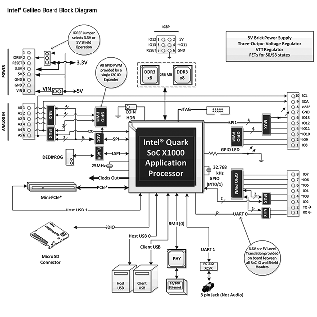
Out of the box there is 262144 bytes available for sketches. As the Arduino is emulated, the hardware for I/O is a little different than you may have expected, and provided by a variety of I2C port expanders, MUXs and so on. For example I2C can only run at 100 kHz in master mode, no slave mode, and similar restrictions on SPI as well. Again, review this page to learn more about the internal hardware differences between an Arduino Uno and Intel Galileo.

Visit this page and scroll down to the block diagram for a visual representation, and while you’re there – review the entire page to learn more about the specific Arduino Uno R3 implementation on the Galileo. A lot of work has been done to allow successful emulation of the Arduino using the Quark CPU and internal OS. For example the EEPROM library just works, and has 11264 bytes of storage.

You can get an idea of what is supported “out of the box” by reviewing the libraries included with the Galileo’s IDE installation, for example:

So most of the basic requirements are covered at the time of writing. And unlike some other SBCs emulating Arduino, the onboard Ethernet “just works” as it should with the Ethernet library – and the USBHost library can take advantage of the matching socket on the board. Again – research is the key, so spend some time determining if the Galileo can solve your problems.

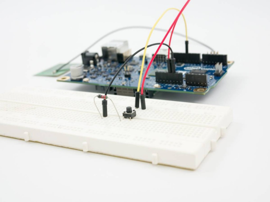
One interesting example of the limitations of the “emulated” Arduino is the speed, and this has been highlighted by Al Williams of Dr Dobb’s journal – who ran a simple sketch to see how fast a digital output pin could be set. As GPIO is provided by external SPI- and I2C-based interface ICs, there will be a speed hit. But how much? Naturally we can’t use port manipulation so we’re back to simple digitalWrite functions with the following sketch:

int pin = 2;
boolean a = false;
void setup() 
{                
  pinMode(pin, OUTPUT);     
}

void loop() 
{
  digitalWrite(pin, a=!a);
}

An Arduino Uno running the sketch was clocked at 96.34 kHz:

… and the Intel Galileo was clocked at … 225.2 Hz:

This test isn’t a criticism of the Galileo, just an example of what you need to keep in mind when using it. If you’re curious about the real-time clock it’s accessed via Linux. Finally, there’s a list of known issues on the Intel forum – so check this out to get a grip on what is and is not working in terms of Arduino compatibility. One more thing – you will need a memory card installed if you want the Galileo to remember sketches after power-off.

Update – thanks to our friends (!) at reddit, you can push some I/O faster – see this post in the Intel forum.

Linux – internal

The Galileo arrived pre-loaded with a very light version of Linux, however due to the lack of video output you need to access the “computer” via some old-school methods. And thus one method is via Telnet over Ethernet. If you don’t have a Telnet client, try PuTTY. To get started, ensure you have your Galileo connected to power, client USB to PCm and to your LAN. Then upload the following sketch to your Galileo:

// https://communities.intel.com/message/213624
void setup()
{
  system("telnetd -l /bin/sh");
}

void loop()
{
  system("ifconfig eth0 > /dev/ttyGS0");
  sleep(10);
}

The observant will notice by using the system function you can send instructions to the Linux command line from your Arduino sketch. And any resulting output text can be sent to the serial monitor by directing it to ttyGS0.

Anyhow, the above sketch will run the ifconfig command and return relevant networking data about your Galileo – including its IP address:

Once you have the IP address, you can Telnet in and command your Galileo just like it’s 1992:

Don’t get too excited, there isn’t that much installed (e.g. no gcc or make). For more information on the Poky linux, visit the project page. Apart from running vi my *nix memory is a bit vague, however the onboard system is quite minimal. If you want to do anything serious, such as use a WiFi or other PCIe card – you’ll need to boot your Galileo with an external OS stored on a microSD card. Another way of looking at the Galileo is that it’s a board not for development with, but for running code built on a different system and then loaded onto the Galileo.

Linux – external

As I haven’t been a *nix user for a very long time, it didn’t seem worthwhile to spend a whole day preparing for an installing the external OS on the Galileo for review. However from what I can tell you’ll need to do this to run anything substantial including WiFi adaptors, python, node.js and so on. Which in my personal opinion sort of ruins the Galileo for me. Other SBCs can do all of this a lot easier, cheaper and with better documentation.

Arduino Support

As the Galileo is from Intel and not Arduino, you need to ask for support in the Intel forum. This will be an interesting test for Intel, will they invest in a substantial support effort or just stand back and say it’s all open source? Time will tell. In the meanwhile there is a gallery hosted by Intel with links to different projects.

Conclusion

Once again – remember that the Galileo is a limited single-board computer that emulates (to a certain, varying degree) an Arduino Uno R3. It is a contender if you need to integrate some Arduino-based control with software running on a light Linux machine, and all in a compact board. Or if you want to experiment with USB host and Ethernet on the Arduino platform at the same time, this could be a cheaper and more powerful option. Support is there if you can use Google, however this is not the idea beginners’ Arduino board. So don’t be a sheep and rush out and buy one after reading the marketing blurb – do your own research first.

Personally I would say that if you have a need for the specific hardware interfaces of the Galileo, and have a full understanding of the board limitations – then it’s the board for you. Otherwise if you want to experiment with a full single-board computer with Arduino compatibility, get a pcDuino. Full-sized images are available on flickr.

And if you enjoyed this article, or want to introduce someone else to the interesting world of Arduino – check out my book (now in a third printing!) “Arduino Workshop”.

Have fun and keep checking into tronixstuff.com. Why not follow things on twitterGoogle+, subscribe  for email updates or RSS using the links on the right-hand column, or join our forum – dedicated to the projects and related items on this website. Sign up – it’s free, helpful to each other –  and we can all learn something.

[Note – Intel Galileo purchased for review by tronixstuff.com and not a promotional consideration]

The post Review – Intel Galileo Arduino-compatible Development Board appeared first on tronixstuff.

Tronixstuff 12 Feb 03:59

First look – Arduino Yún

Introduction

After being announced in May this year, the new Arduino Yún has arrived in the crowded marketplace – and I snapped up one of the first to arrive in Australia for an initial review. The purpose of which is to run through the out of box experience, and to see how easy it was to get the Yún working with the promised new features.

[Update – over time we’ll publish tutorials specifically for the Yún, which are listed here.]

The Yún introduces some interesting new combinations of hardware and connectivity, all within the familiar form-factor. Which gives us plenty to examine and write about, so let’s get started. First, a quick look around the Yún:

Notice the stickers on the header sockets, useful for beginners or the absent-minded…

The usual TX/RX and D13 LEDs, plus notifiers for power, WiFi, LAN and USB use…

Ethernet, USB programming, USB host…

Again with the stickers…

The rear is quite busy. You can also see “Made in Taiwan” – a first for Arduino. I believe the reason for this was due to the new Atheros chipset requirements. Did you notice the multiple reset buttons? There are three – one for the Arduino, one for wifi and one to reboot Linino. As you can see there’s a lot of circuity on the bottom of the Yún, so it would be prudent to use some short standoffs to elevate the board and protect the bottom. Before moving on, you might like the following video where the Arduino team introduce the Yún:

Specifications

The Yún is based around the Arduino Leonardo-specification board – thus you have the ATmega32U4 microcontroller and the usual Leonardo functions. Note you cannot feed wild DC voltages into the Vin pin – it must be a regulated 5V. And the DC socket has gone, so for a solid connection you might want to make or buy your own power shield.

However there is so much more… underneath a small metal shield below the digital I/O pins is an Atheros AR9331 CPU running a Linux distribution based on OpenWRT named Linino. This Atheros part of the board is connected to a microSD socket, 10/100 Ethernet port, a USB 2.0 socket for host-mode functions and also has IEEE 802.11b/g/n WiFi, and Power-over-Ethernet support (with an optional adaptor).

And all of that is connected to the Arduino side of things via a simple serial “bridge” connection (with it’s own library) – which gives the Arduino side of the board very simple methods of controlling the other onboard hardware.

Getting started with the Yún WiFi

First thing is to download and install the new IDE, version 1.5.4. This is for Due and Yún, so keep your older installations as well. On the general Arduino side of things nothing has changed, so we’ll move on to the more interesting side of the board. The first of these is to setup and experiment with the onboard WiFi. After connecting your board to USB for power, you can connect to it with your PC’s WiFi:

… at which point you connect to the Yún network. Then visit 192.168.240.1 from a web browser, and you’re presented with a page that asks for the default password, which is … “arduino”:

At which point you’re presented with the relevant details for your Yún:

… such as the IP address, MAC address, etc. Make note of your MAC address, you might need it later. From here you can configure the Yún WiFi details, for example the name and password, and also the details of your existing WiFi network which can be used to access the Yún. Once you save those, the Yún reboots and tells you to connect the PC back to the existing WiFi network:

If for some reason it doesn’t work or you entered the wrong settings – hold down the “WLAN RST” button (next to the USB host socket) for five seconds. This sets the WiFi details in the Yun back to the default … and you can start all over again.

Note that the Yún’s preset IP of 192.168.240.1 may not be suitable for your own network. For example, if your home router is 10.1.1.1 you need to do some detective work to find out the IP address for the Yún. Head into your router’s administration pages and look for your DHCP Client Log. It will show a list of devices that are connected to the network, including their MAC and IP address – for example:

Then it’s a simple matter of finding the MAC address in the list and the matching IP. Once you have the IP address, enter that into a web browser and after being prompted for the Yún’s password, you’re back to the welcome page with the IP, MAC addresses etc.

WiFi Sketch Uploading

Once your Yún is on the same WiFi network as the PC running the IDE – you can upload a sketch over WiFi! This is possible due to the bridge between the Atheros section on the board and the Arduino hardware. Just select the board type as normal in the IDE, and the port (the IP address version):

… then hit Upload as normal, enter the password:

and you’re done. Awesome.

Console-based control of Arduino over WiFi

There’s a neat example that demonstrates how you can control the Arduino over the WiFi using a console terminal on the PC. Upload this sketch (from http://arduino.cc/en/Guide/ArduinoYun#toc13):

#include <Console.h>

const int ledPin = 13; // the pin that the LED is attached to
int incomingByte;      // a variable to read incoming serial data into

void setup() {
  // initialize serial communication:
  Bridge.begin();
  Console.begin(); 

  while (!Console){
    ; // wait for Console port to connect.
  }
  Console.println("You're connected to the Console!!!!");
  // initialize the LED pin as an output:
  pinMode(ledPin, OUTPUT);
}

void loop() {
  // see if there's incoming serial data:
  if (Console.available() > 0) {
    // read the oldest byte in the serial buffer:
    incomingByte = Console.read();
    // if it's a capital H (ASCII 72), turn on the LED:
    if (incomingByte == 'H') {
      digitalWrite(ledPin, HIGH);
    } 
    // if it's an L (ASCII 76) turn off the LED:
    if (incomingByte == 'L') {
      digitalWrite(ledPin, LOW);
    }
  }
}

Then load your terminal software. We use PuTTY on Windows. Run the terminal software, then login as root, then telnet to “localhost 6571”:

You can then send characters to the Yún just as you would with a USB-connected Arduino via the serial monitor. With the example above you’re turning the D13 LED on and off, but you can get the idea.

The “Internet of Things”

Arduino has teamed up with a service called “Temboo” – which gives you over 100 APIs that your Yún can hook up with to do a myriad of things, such as send tweets, get weather data from Yahoo, interact with Dropbox, etc. This is done easily and explained quite well at the Temboo website. After signing up for Temboo (one account seems to be free at the moment) we tried the Yahoo weather API.

You enter the parameters using an online form in Temboo (in our example, the address of the area whose weather forecast we required), and the Temboo site gives you the required Arduno sketch and header file to upload. And you’re done. With this particular example, I wanted the weather in Sydney CBD – and once running the data is returned to the serial monitor, for example:

It was great to see that work the very first time, and a credit to Temboo and Arduino for making it happen. But how?

There is a Temboo client in the Linino OS, which is the gateway to the API via WiFi, and also communicates with the Arduino via the serial bridge. The Arduino Temboo library can then interact with the Linino client without complex code. The weather data is then returned back from the Internet via the Temboo client and fed to the Arduino serial port, where you can parse it with your own code. This looks like a lot of fun, and also could be quite useful – for example capturing data and sending it to a Google Docs spreadsheet. For more information, check out the Temboo website.

However you can delve deeper and create your own APIs, matching code – and perhaps other services will develop their own APIs in the near future. But for now, it’s a good start.

Where to from here? And support?

This article has only scratched the surface (but not bad considering the board arrived a few hours ago). There’s plenty more examples on the getting started page, in the IDE (under “Bridge”) – plus a dedicated Arduino Yún forum. And check out this gmail notifier. In the near future we’ll create some of our own tutorials, so stay tuned.

Is the Yún a completely open-source product? 

Well it says “open source electronics prototyping platform” on the rear, but is this true? The Arduino Leonardo-side of the board is. However the Atheros AR9331 chip is not. Nevertheless, are you really going to reproduce your own AR9331? So it doesn’t really matter. Being a pragmatist I propose that the Yún solves the problem of Arduino and Internet connectivity quite well for the non-advanced user – so not being totally OSHW isn’t an issue.

Support

This board is very new to us here, so for questions or support please ask on the dedicated Arduino Yún forum.

Conclusion

Since the popularity of various single-board computers has increased exponentially over the last few months, some may say that the Yún is perhaps too little, too late. After only having the Yún for a few hours before writing this article, personally I disagree with this statement – the Yún is a device that still gives us the wide range of hardware control, and what looks to be a very simple method of connectivity that surely is cheaper and less prone to issues than the original Arduino WiFi shield.

What the Yún gives us is a simple, well-executed method of getting our Arduino connected to the outside world – and in a manner that won’t confuse or put off the beginner or intermediate user. So for now, it’s a win.

What do you think? Leave a comment below.

And for more detail, full-sized images from this article can be found on flickr. And if you’re interested in learning more about Arduino, or want to introduce someone else to the interesting world of Arduino – check out my book (now in a third printing!) “Arduino Workshop” from No Starch Press.

In the meanwhile have fun and keep checking into tronixstuff.com. Why not follow things on twitterGoogle+, subscribe  for email updates or RSS using the links on the right-hand column? And join our friendly Google Group – dedicated to the projects and related items on this website. Sign up – it’s free, helpful to each other –  and we can all learn something.

The post First look – Arduino Yún appeared first on tronixstuff.

Tronixstuff 18 Sep 14:39

Kit Review – Maniacal Labs Epoch Clock

Introduction

The subject of our latest kit review is the “Epoch Clock” from Maniacal Labs, a new organisation started by three young lads with some interesting ideas. Regular readers will know we love a clock – so when the opportunity came to review this one, we couldn’t say no.

At this point you may be thinking “what is Epoch time anyway?”. Good question! It is the number of seconds elapsed since the first of January, 1970 (UTC) – and used by Unix-based computers as the start of their time universe. (For more on the theory of Epoch time, check out Wikipedia). For example – 1379226077 Epoch time is Sun, 15 Sep 2013 06:21:17 GMT. That’s a lot of seconds. If you’re curious, you can do more calculations with the EpochTime website.

Moving forward, this clock kit will show Epoch time in full 32-bit binary glory, using a DS1307 real-time clock IC (with backup battery) and is controlled with an ATmega328P-PU – so you can modify the code easily with the Arduino IDE or WinAVR (etc).

Assembly

The creators have spent a lot of time on not only the packaging and out-of-box-experience, but also the documentation and setup guide – so as long as you’re fine with simple through-hole soldering the kit will not present any challenges. The kit arrives in a sturdy box:

… with well packaged components. Everything is included for the finished product, as well as IC sockets, the RTC backup battery and a USB cable so you can power the clock from a USB hub:

The PCB is a good thickness, and has a clear silk-screen and solder mask:

Construction is simple, just follow the step-by-step instructions. Starting with the USB socket for power:

… then the resistors:

… the LEDs:

… all 32 of them. Note that the LEDs don’t sit flush with the PCB, so a little effort is required to keep them aligned:

 Then the rest of the components just fit as expected. I’ve also added the included header pins for an FTDI programming cable and ICSP to keep my options open:

Then simply fit the battery, insert the ICs and you’re done:

Using the clock

The microcontroller is pre-programmed, so you can use the clock straight away. You will however need to set the time first. To make this incredibly easy, there is a special web page that displays the current time and Epoch time, which steps you through the process of setting the time using the buttons.

Or with some code available on the kit github page and a programming cable, you can automatically sync it to the clock. Once setup, the battery will keep the current time in the RTC nicely. The clock is powered by 5V, which is easily supplied with the included USB cable, or you can always hack in your own feed.

So what does Epoch time in 32-bit binary look like? Here’s a short video of the clock in action:

Reading the time requires converting the binary number displayed with the LEDs back to a decimal number – which is of course the Epoch count of seconds since 1/1/1970. Math teachers will love this thing.

But wait, there’s more!

If you get tired of the blinking, there’s a test function which is enabled by holding down both buttons for a second, which turns the Epoch Clock into a nifty Larson Scanner:

To create your own sketches or examine the design files in more detail, it’s all on the clock github page. From a hardware perspective you have an ATmega328P-PU development board with a DS1307 battery-backed real-time clock – with 32 LEDs. So you could also create your own kind of clock or other multi-LED blinking project without too much effort. Review the EpochClockSchematic (.pdf) to examine this in more detail.

Conclusion

I really enjoyed this kit – it was easy to assemble, I learned something new and frankly the blinking LEDs can be quite soothing. The clock would make a great for a conversation-starter in the office, or would make an ideal gift for any Sheldon Cooper-types you might be associated with. Or have competitions to see who can convert the display to normal time. After shots.

Nevertheless it’s a fun and imaginative piece of kit, fully Open Hardware-compliant – and if you’ve made it this far – get some and have fun. Full-sized images are on flickr. Interested in Arduino? Check out my new book “Arduino Workshop” from No Starch Press.

In the meanwhile have fun and keep checking into tronixstuff.com. Why not follow things on twitterGoogle+, subscribe  for email updates or RSS using the links on the right-hand column? And join our friendly Google Group – dedicated to the projects and related items on this website. Sign up – it’s free, helpful to each other –  and we can all learn something.

[Note – The kit reviewed was a promotional consideration from Maniacal Labs]

The post Kit Review – Maniacal Labs Epoch Clock appeared first on tronixstuff.

Tronixstuff 15 Sep 10:29

WiFi-equipped Arduino Yun now available for $69 (video)

If you were wondering what happened to the Arduino Yun after it missed its original June release target, you can relax: it's now on sale worldwide. As promised, the $69 (€52) design combines a garden variety Leonardo board with a WiFi system-on-chip running Limino, giving owners a customizable wireless access point with Ethernet, USB and a microSD slot. Tinkerers can also program the Arduino component over the air using a newly updated developer environment. Those already sold on the concept can buy an Arduino Yun at the source link, while newcomers can check out an introductory video after the break.

Filed under: Misc, Networking

Comments

Via: Arduino Blog

Source: Arduino Store

Engadget 11 Sep 14:51