Posts with «led» label

Handwashing Timer Makes Sure the Suds Stay On Long Enough

“Twinkle, Twinkle, Little Star”? How we wonder why you’d resort to singing a ditty to time your handwashing when you can use your social isolation time to build a touch-free electronic handwash timer that the kids — and you — might actually use.

Over the last few months, pretty much everyone on the planet has been thrust into strange, new, and oftentimes scary practices to limit the spread of the SARS-CoV-2virus and the disease it causes, COVID-19. Judging by the number of people we’ve seen leaving public restrooms without a visit to the washbasin before the outbreak began — and sadly all too often since — we collectively have a lot of work to do in tightening up our handwashing regimens. Time on target and plenty of friction are the keys to that, and [Denis Hennessy]’s “WashTimer” aims to at least help you out with the former. His build is as simple as can be: an Arduino driving an LED matrix when a proximity sensor fires. Wave your dirty paws in front of the unit as you start to scrub up, and the display goes through a nicely animated 20-second countdown, at which time it’s safe to rinse off.

[Denis] purposely made this design as simple and as customizable as possible. Perhaps you’ve got a Neopixel ring lying about rather than the LED matrix, or maybe an ultrasonic sensor would work better for you. Be creative and take this design where it needs to go to suit your needs. We can’t stress enough that handwashing is your number one defense; if you don’t need to moisturize your hands at least three times a day, you’re probably not washing often or long enough. And 20 seconds is way longer than you think it is without a prompt.

Matrix and Joystick

For the original tutorial, please visit: https://arduinobasics.blogspot.com


Project Description

In this project, we will use a little joystick to move a pixel around an 8x8 LED matrix. The joystick has a built-in button, such that when you press down onto the joystick, the colour of the pixel will change from red to blue to green. This is a very simple project, however, controlling the matrix adds a certain level of complexity. You will need to understand binary notation and bit-shifting techniques to grasp the concept of this tutorial.

All of the parts used in this project can be obtained from digitspace.com


Libraries

The SPI library is required for this project. However, this library is built into the current version of the Arduino IDE. No additional download is required. Just make sure to include it at the top of the sketch.


Arduino Code

The Arduino IDE can be downloaded from the official Arduino website: here.
Copy and paste the following code into your Arduino IDE and upload it to the Arduino UNO.


Connections


Project Video

As you can see from the video above, the pixel changes colour when the button is pressed. The position of the pixel relates to the position of the joystick. The lag between the joystick movement and pixel movement is minimal, and very satisfying.


Conclusion

This was a very fun and satisfying project that showcases the interaction between a joystick and a 8x8 LED matrix with the help of an Arduino UNO. This project was sponsored by the kind people at digitspace. Without their sponsorship, this tutorial would not have been possible. Please visit their website for some nice deals on Arduino related products.

If you found this tutorial helpful, please consider supporting me by buying me a virtual coffee/beer.

$3.00 AUD only

Social Media

You can find me on various social networks:

Follow me on Twitter: ScottC @ArduinoBasics.
I can also be found on Instagram, Pinterest, and YouTube.
And if all else fails, I have a server on Discord.


ScottC 09 Mar 07:41
8x8  arduino  ce  clk  fun  joystick  led  matrix  module  mosi  pixel  programming  spi  sw  tutorial  uno  x  y  

Dinural Reef Control Realistically Insolates Your Aquarium

[Phillip]’s project is not just great for learning new words, it also shows just how complex natural systems can be. 

As we know from news around the word, reefs are delicate systems prone to damage from just about any imaginable threat. Escaped aquarium fish, sunscreen, and the wayward feet of well meaning tourists to name a few. So it’s no wonder that aquarium hobbyists sometimes go to incredible lengths to simulate the natural environments these creatures live in.

While [Phillip] is still tinkering with his designs for this project, we found the data he included really interesting. His goal is to be able to plug in any coordinate on the earth and have the lights replicate the location. That includes not just the sun, but also the light from the moon as many corals seem to only spawn during certain tides. Of course no LED is perfect so he’s even experimenting with putting light sensors under the water to provide a feedback loop to make it perfect.

We really like the ambition of this project and we hope he continues.

Hack a Day 04 Jan 06:00
arduino  coral  led  led hacks  light  reef  simulate  tide  

Create your own Arduino Library

Project Description

In this short tutorial I will show you how to create your own Arduino Library. Making your own library seems daunting at first, but I will show you that it is not much harder than writing your own script/sketch. I would advise that you comment you code clearly, because when you come back to it in 5 years time, it will help to navigate you through your code at this time in history. Here we go, let's go through the process of creating a very simple Arduino library.

Parts Required

  • Arduino UNO or compatible board

Project Steps

Before we begin, there are a few questions you must ask yourself:

  1. What will the library be called ?
  2. What will the library do ?
  3. What are you trying to simplify?

For our library, these are the answers to the questions above:

  1. BlinkMe
  2. It will blink an LED attached to one of the digital pins
  3. The aim is to reduce the blink commands to a single line

Create a Folder

Create a folder on your computer which will be used to house all of the files in this project. Name the folder the same name as the library. In this case we will name it "BlinkMe". Make sure you use consistent naming throughout the tutorial. Capital and lowercase letters do matter.

Create the files

Using any text based editor (eg. notepad++, PSPad, Notepad2 etc), you will need to create 3 blank files:

  • The C++ file (BlinkMe.cpp) : Library code containing all of the functions
  • The Header file (BlinkMe.h): Contains the library function declarations
  • keywords.txt : Used for syntax highlighting within the Arduino IDE

I will tell you what you need to write inside each of these files, but make sure you have the blank BlinkMe.cpp, BlinkMe.h and keywords.txt files inside of the BlinkMe folder. Some people start by creating the header file first, but I personally like to start with the CPP file.
We will now look to populate the BlinkMe C++ file:

The C++ file (.cpp)

This file will contain all of the functions in your new library.
The first thing you will need to do is include the Arduino.h file. This will drag in all of the relevant Arduino code necessary for your library to function with an Arduino. And while we haven't yet created the header file (BlinkMe.h), we need to import that also. So the first two lines should be:

#include <Arduino.h>
 #include <BlinkMe.h>

The next section of code is the "constructor". This will be responsible for constructing the BlinkMe object. The BlinkMe object will allow you to call any of the public functions within the BlinkMe library. The constructor will allow us to define the default variables or constants.

BlinkMe::BlinkMe(){
    _dPin = 13;
 }

Sometimes we will want to blink an LED on a different pin. So we will create a function to set the pin that we would like use.

void setOUTPUT(int dPin){
    _dPin = dPin;
    pinMode(_dPin, OUTPUT);
 }

The only thing left is to create the useful part of the code. We will create a simple function that will blink the LED for a set duration. The function will have a parameter, which will be used to set the blink duration.

void blink(unsigned long delay_1){
    _delay_1 = delay_1;
    digitalWrite(_dPin, HIGH);
    delay(_delay_1);
    digitalWrite(_dPin, LOW);
    delay(_delay_1);
 }

Here is the complete "BlinkMe.cpp" file:

The Header file (.h)

The header file will be used to create the library function declarations. Open the "BlinkMe.h" file.
The first step is to check to make sure that the library is NOT already defined:

#ifndef BlinkMe_h

If it is not defined, then we must define the library:

#define BlinkMe_h

We then need to provide access to the standard Arduino types and constants

#include "Arduino.h"

And finally create the BlinkMe class:

//Create the class BlinkMe
class BlinkMe{
    public:
        BlinkMe();
        void setOUTPUT(int dPin);
        void blink(unsigned long delay_1);
    private:
        int _dPin;
        unsigned long _delay_1;
 };
#endif

Here is the complete header file:

keywords.txt (optional)

The keywords.txt file will contain the keywords for the library which will allow appropriate syntax highlighting. This file is optional, however it will highlight your classes or functions based on the keyword mapping.

  • LITERAL1: specifies constants (eg. HIGH, LOW,
  • KEYWORD1: specifies classes (eg. Serial)
  • KEYWORD2: specifies methods and functions (eg. analogRead, digitalWrite, delay)
  • KEYWORD3: specifies structures (eg. if, while, loop)
You need to make sure you use a single tab between the keyword and the "KEYWORD" mapping. In our example, BlinkMe is a class, so that would be a KEYWORD1. On the other hand, "blink" is a function, so that would be a KEYWORD2. So the keywords.txt file will contain the following text:

BlinkMe     KEYWORD1
setOUTPUT   KEYWORD2
blink       KEYWORD2

Example Sketch (optional)

It is often useful to include an sketch that provides an example of the library in use. It provides some context. If you plan to include the sketch in your library, then you must follow these simple rules:

  1. Create an "examples" folder.
  2. Create an example sketch, an place it within a folder of the same name as the sketch
  3. Place the sketch folder inside of the examples folder
You will end up with something like: examples/example_sketch/example_sketch.ino
In our case it will be: examples/blinkTest/blinkTest.ino

Here is the example sketch for this library (Save as blinkTest.ino):


The library

Here is a picture of the library contents:

And now the only thing left is to zip up the library folder and import it into the Arduino IDE. Use whatever program you want to zip up the BlinkMe folder, and note the location of the zip file. You need to import the zip file into the Arduino IDE:

  • Arduino IDE > Sketch > Include Library > Add .ZIP Library...
  • Select the library zip file you just created, and select "Open".
  • You can now use your library in the Arduino IDE.
  • Test it by running your example sketch: File > Examples > BlinkMe > blinkTest

Download

You can download the entire library here:
BlinkMe Library

Conclusion

In this tutorial, I showed you how to create a simple Arduino library. If you would like so see another example, have a look at my ToggleTimer library, which is very useful when trying to blink an LED without using a delay.You don't have to limit yourself to LEDs, you can use it for other projects where delay gets in the way. ToggleTimer is a non-blocking timer that toggles between two states.


If you found this tutorial helpful, please consider supporting me by buying me a virtual coffee/beer.

$3.00 AUD only

Social Media

You can find me on various social networks:

Follow me on Twitter: ScottC @ArduinoBasics.
I can also be found on Instagram, Pinterest, and YouTube.
And if all else fails, I have a server on Discord.


ScottC 29 Dec 10:09
arduino  blink  diy  led  library  tutorial  

Optical Communication Using LEDs Alone

We’re all used to the humble LED as a ubiquitous source of light, but how many of us are aware that these components can also be used as photodiodes? It’s something [Giovanni Blu Mitolo] takes us through as he demonstrates a simple data link using just a pair of LEDs and a couple of Arduinos. It’s a showing off his PJON networking layer, and while you’d need a bit more than a couple of LEDs on breadboards for a real-world application, we still think it’s a neat demonstration.

PJON itself is very much worth a look, being an implementation of a robust and error-tolerant network for Arduinos and other small microcontroller platforms. It has a variety of communication strategies for various different media, and as this LED demonstration shows, its strength is that it’s capable of working through media that other networks would balk at. Whether it’s controlling home automation through metal heating ducts or providing an alternative to LoRa at 433 MHz, it’s definitely worth a second look. We’ve mentioned it before, but remain surprised that we haven’t seen it more often since. Take a look, the video is below the break.

Hack a Day 22 Dec 09:00

Interactive Core Memory Shield Helps Explains The Past

[Andy Geppert] sends in his incredibly clever interactive core memory shield. 

In a great display of one hacker’s work being the base for another’s, [Andy] started out with [Jussi Kilpelainen]’s core memory shield for Arduino.  As he was playing with the shield he had a desire to “see” the core memory flipping and got the idea to add an LED matrix aligned behind the individual cores.

The first iteration worked, but it only showed the state that the Arduino believed the core memory to be in. What he really wanted was a live read on the actual state. He realized that an Adafruit Featherwing 8×8 matrix display also fits behind the core memory. Now the LEDs update based on the read state of the core memory. This allows him to flip the individual bits with a magnetic stylus and see the result. Very cool.

You can see a video of it working after the break.

A Farewell To YouTube Sub Counters Set To Break With API Change

Of all the things you never would have guessed you’d need just ten years ago, a YouTube subscriber counter would probably rank highly. You would have guessed that the little hits of dopamine accompanying each tick upward of a number would be so addictive?

As it turns out, lots of people wanted to keep a running total of their online fans, and a bewilderingly varied ecosystem of subscriber counters has cropped up. All of them rely on the API that YouTube exposes for such purposes, which as [Brian Lough] points out is about to change and break every subscription counter ever made. In the YouTube sub counter space, [Brian] is both an enabler – he built an Arduino wrapper to fetch YT sub counts easily – and a serial builder of displays for other YouTubers. The video below shows a collection of his work, many based on RGB LED matrix display, like the one used in his Tetris-themed sub counter. They’re all well-built, nice to look at, and sadly, destined for obsolescence sometime in August when the API changes.

The details of the API changes were made public in April, and for the subs count it amounts to rounding the count and displaying large counts as, for instance, 510k as opposed to 510,023. We’re confident that [Brian] and other display builders will be able to salvage some of their counters with code changes, but others will probably require hardware changes. Thanks, YouTube.

Hack a Day 02 Aug 03:00

Tutorial – Arduino and Four Digit Seven Segment Display Module

This is a quick start guide for the Four Digit Seven Segment Display Module and Enclosure from PMD Way. This module offers a neat and bright display which is ideal for numeric or hexadecimal data. It can display the digits 0 to 9 including the decimal point, and the letters A to F. You can also control each segment individually if desired. 

Each module contains four 74HC595 shift registers – once of each controls a digit. If you carefully remove the back panel from the enclosure, you can see the pin connections:

If you’re only using one display, use the group of pins at the centre-bottom of the board. From left to right the connections are:

  1. Data out (ignore for single display use)
  2. VCC – connect to a 3.3V or 5V supply
  3. GND – connect to your GND line
  4. SDI – data in – connect to the data out pin on your Arduino/other board
  5. LCK – latch – connect to the output pin on your Arduino or other board that will control the latch
  6. CLK – clock – connect to the output pin on your Arduino or other board that will control the clock signal

For the purposes of our Arduino tutorial, connect VCC to the 5V pin, GND to GND, SDI to D11, LCK to D13 and CLK to D12. 

If you are connecting more than one module, use the pins on the left- and right-hand side of the module. Start with the connections from your Arduino (etc) to the right-hand side, as this is where the DIN (data in) pin is located.

Then connect the pins on the left-hand side of the module to the right-hand side of the new module – and so forth. SDO (data out) will connect to the SDI (data in) – with the other pins being identical for connection. 

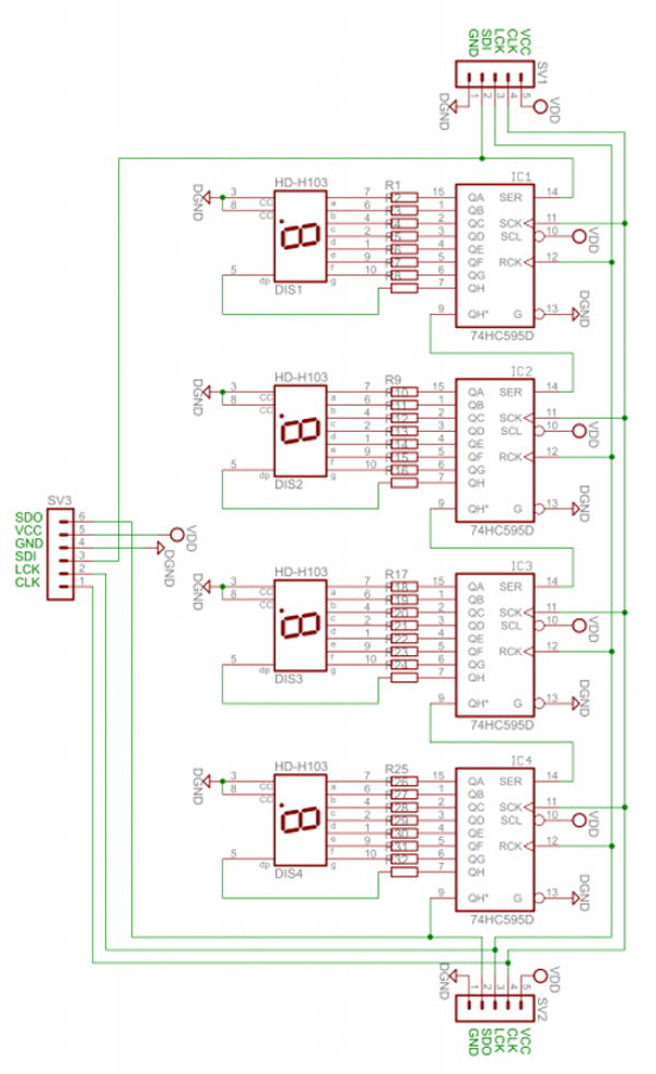
The module schematic is shown below:

Arduino Example Sketch

Once you have made the connections to your Arduino as outlined above, upload the following sketch:

// Demonstration Arduino sketch for four digit, seven segment display with enclosure
// https://pmdway.com/collections/7-segment-numeric-leds/products/four-digit-seven-segment-display-module-and-enclosure
int latchPin = 13; // connect to LCK pin intclockPin = 12; // connect to CLK pin intdataPin = 11; // connect to SDI pin int LED_SEG_TAB[]={ 0xfc,0x60,0xda,0xf2,0x66,0xb6,0xbe,0xe0,0xfe,0xf6,0x01,0xee,0x3e,0x1a,0x7a,0x9e,0x8e,0x01,0x00}; //0 1 2 3 4 5 6 7 8 9 dp . a b c d e f off void setup() { //set pins to output so you can control the shift register pinMode(latchPin, OUTPUT); pinMode(clockPin, OUTPUT); pinMode(dataPin, OUTPUT); } void displayNumber(int value, boolean leadingZero) // break down "value" into digits and store in a,b,c,d { int a,b,c,d; a = value / 1000; value = value % 1000; b = value / 100; value = value % 100; c = value / 10; value = value % 10; d = value; if (leadingZero==false) // removing leading zeros { if (a==0 && b>0) { a = 18; } if (a==0 && b==0 && c>0) { a = 18; b = 18; } if (a==0 && b==0 && c==0) { a = 18; b = 18; c = 18; } if (a==0 && b==0 && c==0 && d==0) { a = 18; b = 18; c = 18; d = 18; } } digitalWrite(latchPin, LOW); shiftOut(dataPin, clockPin, LSBFIRST, LED_SEG_TAB[d]); shiftOut(dataPin, clockPin, LSBFIRST, LED_SEG_TAB[c]); shiftOut(dataPin, clockPin, LSBFIRST, LED_SEG_TAB[b]); shiftOut(dataPin, clockPin, LSBFIRST, LED_SEG_TAB[a]); digitalWrite(latchPin, HIGH); } void allOff() // turns off all segments { digitalWrite(latchPin, LOW); shiftOut(dataPin, clockPin, LSBFIRST, 0); shiftOut(dataPin, clockPin, LSBFIRST, 0); shiftOut(dataPin, clockPin, LSBFIRST, 0); shiftOut(dataPin, clockPin, LSBFIRST, 0); digitalWrite(latchPin, HIGH); } void loop() { for (int z=900; z<=1100; z++) { displayNumber(z, false); delay(10); } delay(1000); for (int z=120; z>=0; --z) { displayNumber(z, true); delay(10); } delay(1000); digitalWrite(latchPin, LOW); shiftOut(dataPin, clockPin, LSBFIRST, LED_SEG_TAB[14]); shiftOut(dataPin, clockPin, LSBFIRST, LED_SEG_TAB[13]); shiftOut(dataPin, clockPin, LSBFIRST, LED_SEG_TAB[12]); shiftOut(dataPin, clockPin, LSBFIRST, LED_SEG_TAB[11]); digitalWrite(latchPin, HIGH); delay(1000); digitalWrite(latchPin, LOW); shiftOut(dataPin, clockPin, LSBFIRST, LED_SEG_TAB[16]); shiftOut(dataPin, clockPin, LSBFIRST, LED_SEG_TAB[15]); shiftOut(dataPin, clockPin, LSBFIRST, LED_SEG_TAB[14]); shiftOut(dataPin, clockPin, LSBFIRST, LED_SEG_TAB[13]); digitalWrite(latchPin, HIGH); delay(1000); digitalWrite(latchPin, LOW); shiftOut(dataPin, clockPin, LSBFIRST, LED_SEG_TAB[0]); shiftOut(dataPin, clockPin, LSBFIRST, LED_SEG_TAB[1]); shiftOut(dataPin, clockPin, LSBFIRST, LED_SEG_TAB[2]); shiftOut(dataPin, clockPin, LSBFIRST, LED_SEG_TAB[3]+1); digitalWrite(latchPin, HIGH); delay(1000); digitalWrite(latchPin, LOW); shiftOut(dataPin, clockPin, LSBFIRST, LED_SEG_TAB[7]); shiftOut(dataPin, clockPin, LSBFIRST, LED_SEG_TAB[6]+1); shiftOut(dataPin, clockPin, LSBFIRST, LED_SEG_TAB[5]); shiftOut(dataPin, clockPin, LSBFIRST, LED_SEG_TAB[4]); digitalWrite(latchPin, HIGH); delay(1000); }

After a moment you should see the display spring into action in the same way as in the demonstration video:

How does it work? 

First we define which digital output pins are used for latch, clock and data on lines four to six. On line eight we have created an array which contains values that are sent to the shift registers in the module to display the possible digits and letters. For example, the first – 0xfc – will activate the segments to display a zero, 0x7a for the letter C, and so on. 

From line 20 we’ve created a custom function that is used to send a whole number between zero and 9999 to the display. To do so, simply use:

void displayNumber(value, true/false);

where value is the number to display (or variable containing the number) – and the second parameter of true or false. This controls whether you have a leading zero displayed – true for yes, false for no. 

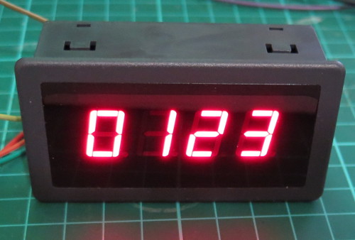
For example, to display “0123” you would use:

displayNumber(123, true);

… which results with:

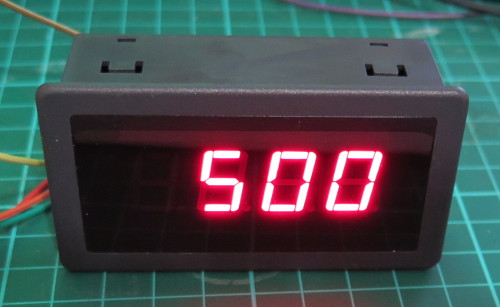
or to display “500” you would use:

displayNumber(500, false);

… which results with:

To turn off all the digits, you need to send zeros to every bit in the shift register, and this is accomplished with the function in the sketch called 

allOff();

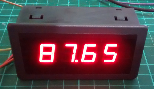
What about the decimal point? 

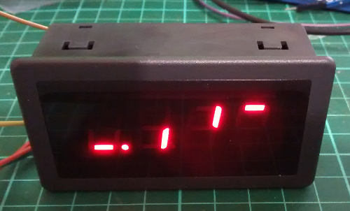
To turn on the decimal point for a particular digit, add 1 to the value being sent to a particular digit. Using the code from the demonstration sketch to display 87.65 you would use:

 digitalWrite(latchPin, LOW);

 shiftOut(dataPin, clockPin, LSBFIRST, LED_SEG_TAB[5]);

 shiftOut(dataPin, clockPin, LSBFIRST, LED_SEG_TAB[6]);

 shiftOut(dataPin, clockPin, LSBFIRST, LED_SEG_TAB[7]+1); // added one for decimal point

 shiftOut(dataPin, clockPin, LSBFIRST, LED_SEG_TAB[8]);

 digitalWrite(latchPin, HIGH);

… which results with:

In-depth explanation of how the module is controlled

As shown in the schematic above, each digit is controlled by a 74HC595 shift register. Each shift register has eight digital outputs, each of which control an individual segment of each digit. So by sending four bytes of data (one byte = eight bits) you can control each segment of the display. 

Each digit’s segments are mapped as follows:

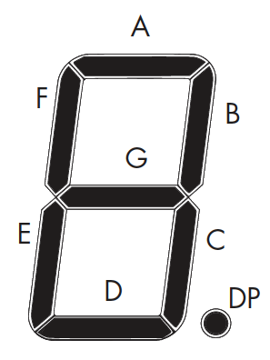
And the outputs from each shift register match the order of segments from left to right. So outputs 0~7 match A~G then decimal point. 

For example, to create the number seven with a decimal point, you need to turn on segments A, B, C and DP – which match to the shift register’s outputs 0,1,2,8. 

Thus the byte to send to the shift register would be 0b11100001 (or 225 in decimal or 0xE1 in hexadecimal). 

Every time you want to change the display you need to re-draw all four (or more if more than one module is connected) digits – so four bytes of data are sent for each display change. The digits are addressed from right to left, so the first byte send is for the last digit – and the last byte is for the first digit. 

There are three stages of updating the display. 

  1. Set the LCK (latch) line low
  2. Shift out four bytes of data from your microcontroller
  3. Set the LCK (latch) line high

For example, using Arduino code we use:

  digitalWrite(latchPin, LOW);

  shiftOut(dataPin, clockPin, LSBFIRST, 0b10000000); // digit 4

  shiftOut(dataPin, clockPin, LSBFIRST, 0b01000000); // digit 3

  shiftOut(dataPin, clockPin, LSBFIRST, 0b00100000); // digit 2

  shiftOut(dataPin, clockPin, LSBFIRST, 0b00010001); // digit 1

  digitalWrite(latchPin, HIGH);

This would result with the following:

Note how the bytes in binary match the map of the digits and their position. For example, the first byte sent was for the fourth digit, and the segment A was turned on. And that’s all there is to it – a neat and simple display. 

This post brought to you by pmdway.com – everything for makers and electronics enthusiasts, with free delivery worldwide.

To keep up to date with new posts at tronixstuff.com, please subscribe to the mailing list in the box on the right, or follow us on twitter @tronixstuff.


Tronixstuff 13 Jul 08:48
arduino  display  led  numeric  pmdway  

A Ping Pong Ball LED Video Wall

Constrained builds are often the most fun. Throw an artificial limit into the mix, like time limiting your effort or restricting yourself to what’s on hand, and there’s no telling what will happen.

[bitluni] actually chose both of those constraints for this ping pong ball LED video display, and the results are pretty cool, even if the journey was a little rough. It seems like using sheet steel for the support of his 15 x 20 Neopixel display was a mistake, at least in hindsight. A CNC router would probably have made the job of drilling 300 holes quite a bit easier, but when all you have is a hand drill and a time limit, you soldier on. Six strings of Neopixels fill the holes, a largish power supply provides the 18 or so amps needed, and an Arduino knock-off controls the display. The ping pong ball diffusers are a nice touch, even if punching holes in them cost [bitluni] a soldering iron tip or two. The display is shown in action in the video below, mostly with scrolling text. If we may make a modest suggestion, a game of Pong on a ping pong ball display might be fun.

[bitluni] says that the display is on its way to Maker Faire Berlin this weekend, so stop by and say hi. Maybe he’ll have some of his other cool builds too, like his Sony Watchman Game Boy mashup, or the electric scooter of questionable legality.

Hack a Day 17 May 16:30

Digital Rain Cloud


Description

This is a very simple project that turns a Rainbow Cube Kit from Seeedstudio, into a digital rain cloud. It features a relaxing rain animation which is ruined by a not-so-relaxing yet somewhat realistic lightning effect. The animation has a very random pattern, and is quite satisfying to watch. The strategically placed cotton wool on the top of the cube makes all the difference to the project, and is sure to impress all of your friends. Luckily, I have done all of the hard work for you. You will find the full source code for the animation sequence below. You just have to provide the Rainbow Cube Kit and the cotton wool. Have fun !!