Learn how to use inexpensive serial backpacks with character LCD modules with your Arduino. This is chapter fifty-eight of our huge Arduino tutorial series.
Introduction
Using LCD modules with your Arduino is popular, however the amount of wiring requires time and patience to wire it up correctly – and also uses a lot of digital output pins. That’s why we love these serial backpack modules – they’re fitted to the back of your LCD module and allows connection to your Arduino (or other development board) with only four wires – power, GND, data and clock.
You can use this with LCD modules that have a HD44780-compatible interface with various screen sizes. For example a 16 x 2 module:

The backpack can also be used with 20 x 4 LCDs. The key is that your LCD must have the interface pads in a single row of sixteen, so it matches the pins on the backpack – for example:

Hardware Setup
Now let’s get started. First you need to solder the backpack to your LCD module. While your soldering iron is warming up, check that the backpack pins are straight and fit in the LCD module, for example:

Then solder in the first pin, while keeping the backpack flush with the LCD:

If it’s a bit crooked, you can reheat the solder and straighten it up again. Once you’re satisfied with the alignment, solder in the rest of the pins:

Now to keep things neat, trim off the excess header pins:

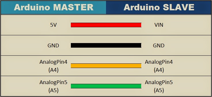
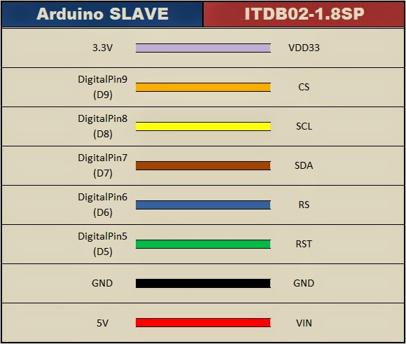
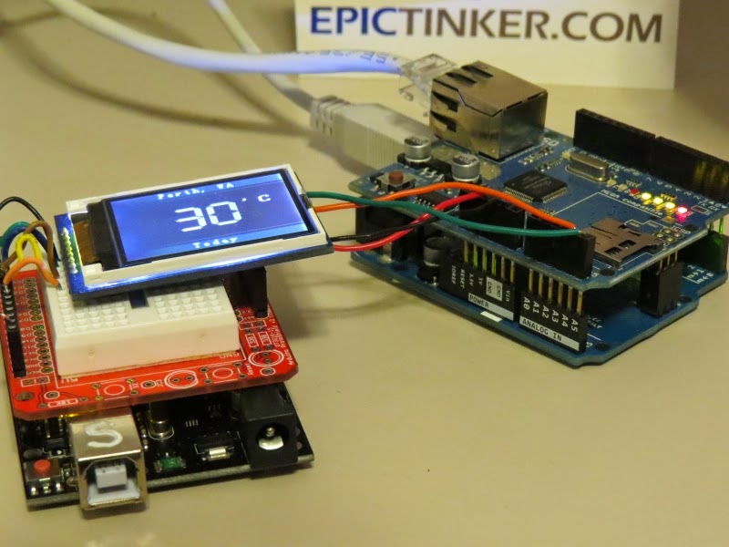
Once you’ve finished trimming the header pins, get four male to female jumper wires and connect the LCD module to your Arduino as shown in the following image and table. Then connect your Arduino to the computer via USB:


Software Setup
The next step is to download and install the Arduino I2C LCD library for use with the backpack. First of all, rename the “LiquidCrystal” library folder in your Arduino libraries folder. We do this just to keep it as a backup.
If you’re not sure where your library folder can be found – it’s usually in your sketchbook folder, whose location can usually be found in the Arduino IDE preferences menu:

Next, visit https://bitbucket.org/fmalpartida/new-liquidcrysta… and download the latest file, currently we’re using v1.2.1. Expanding the downloaded .zip file will reveal a new “LiquidCrystal” folder – copy this into your Arduino libraries folder.
Now restart the Arduino IDE if it was already running – or open it now. To test the module we have a demonstration sketch prepared, simply copy and upload the following sketch:
/* Demonstration sketch for PCF8574T I2C LCD Backpack
Uses library from https://bitbucket.org/fmalpartida/new-liquidcrystal/downloads GNU General Public License, version 3 (GPL-3.0) */
#include <Wire.h>
#include <LCD.h>
#include <LiquidCrystal_I2C.h>
LiquidCrystal_I2C lcd(0x27,2,1,0,4,5,6,7); // 0x27 is the I2C bus address for an unmodified backpack
void setup()
{
// activate LCD module
lcd.begin (16,2); // for 16 x 2 LCD module
lcd.setBacklightPin(3,POSITIVE);
lcd.setBacklight(HIGH);
}
void loop()
{
lcd.home (); // set cursor to 0,0
lcd.print(" tronixlabs.com");
lcd.setCursor (0,1); // go to start of 2nd line
lcd.print(millis());
delay(1000);
lcd.setBacklight(LOW); // Backlight off
delay(250);
lcd.setBacklight(HIGH); // Backlight on
delay(1000);
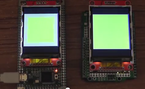
}After a few moments the LCD will be initialised and start to display our URL and the value for millis, then blink the backlight off and on – for example:

If the text isn’t clear, or you just see white blocks – try adjusting the contrast using the potentiometer on the back of the module.
How to control the backpack in your sketch
As opposed to using the LCD module without the backpack, there’s a few extra lines of code to include in your sketches. To review these, open the example sketch mentioned earlier.
You will need the libraries as shown in lines 3, 4 and 5 – and initialise the module as shown in line 7. Note that the default I2C bus address is 0x27 – and the first parameter in the LiquidCrystal_I2C function.
Finally the three lines used in void setup() are also required to initialise the LCD. If you’re using a 20×4 LCD module, change the parameters in the lcd.begin() function.
From this point you can use all the standard LiquidCrystal functions such as lcd.setCursor() to move the cursor and lcd.write() to display text or variables as normal. The backlight can also be turned on and off with lcd.setBacklight(HIGH) or lcd.setBacklight(LOW).
You can permanently turn off the backlight by removing the physical jumper on the back of the module.
Changing the I2C bus address
If you want to use more than one module, or have another device on the I2C bus with address 0x27 then you’ll need to change the address used on the module. There are eight options to choose from, and these are selected by soldering over one or more of the following spots:

There are eight possible combinations, and these are described in Table 4 of the PCF8574 data sheet which can be downloaded from the NXP website. If you’re unsure about the bus address used by the module, simply connect it to your Arduino as described earlier and run the I2C scanner sketch from the Arduino playground.
We hope you enjoyed this tutorial and you can make use of it. Finally, if you enjoyed this tutorial, or want to introduce someone else to the interesting world of Arduino – check out my book (now in a fourth printing!) “Arduino Workshop”.

Have fun and keep checking into
tronixstuff.com. Why not follow things on
twitter,
Google+, subscribe for email updates or RSS using the links on the right-hand column, or join our
forum – dedicated to the projects and related items on this website.
The post Tutorial – PCF8574 backpacks for LCD modules and Arduino appeared first on tronixstuff.


 The old mechanical controller functioned like a player piano. A rotating drum with ridges actuate different cycles in the washing machine. Some of the cycles weren’t working properly so [hydronucleus] ripped them out. With the help of a schematic posted on the washing machine itself, the cycles were able to be programmed into the Arduino.