Posts with «instructables» label

Make your DIY smart glasses running on Arduino

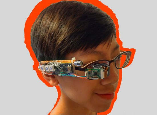
Jordan Fung is a 13-year-old maker and programmer based in Hong Kong. He recently developed Arduino-based smart glasses called Pedosa Glass, which are able to activate, in this first release, a flashlight and a timer:

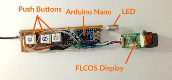
The Pedosa Glass is powered by a single Arduino Nano running an “operating system” developed by me.
There is a tiny FLCOS display in the front. The AV signal from the Arduino will be displayed on it. It is equipped with 3 push buttons, in which 2 of them are control buttons and one of them be the home button, also equipped with a super-bright white LED for use as a flashlight.

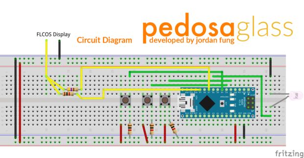
In the picture below you can explore the electronic scheme:


Jordan is working hard to add new applications and features to the project but in the meanwhile he shared his work on a great tutorial on Instructables.

Interview: NIcole Grimwood on Electronics (and Cake)

Nicole Grimwood is working towards a dual degree in engineering from Columbia University and liberal arts from Scripps College.

Read more on MAKE

The post Interview: NIcole Grimwood on Electronics (and Cake) appeared first on Make: DIY Projects, How-Tos, Electronics, Crafts and Ideas for Makers.

Vibrating Distance Torch Illuminates the Dark without Light

If you’ve ever had to move around in a dark room before, you know how frustrating it can be. This is especially true if you are in an unfamiliar place. [Brian] has attempted to help solve this problem by building a vibrating distance sensor that is intuitive to use.

The main circuit is rather simple. An Arduino is hooked up to both an ultrasonic distance sensor and a vibrating motor. The distance sensor uses sound to determine the distance of an object by calculating how long it takes for an emitted sound to return to the sensor. The sensor uses sounds that are above the range of human hearing, so no one in the vicinity will hear it. The Arduino then vibrates a motor quickly if the object is very close, or slowly if it is far away. The whole circuit is powered by a 9V battery.

The real trick to this project is that the entire thing is housed inside of an old flashlight. [Brian] used OpenSCAD to design a custom plastic mount. This mount replaces the flashlight lens and allows the ultrasonic sensor to be secured to the front of the flashlight. The flashlight housing makes the device very intuitive to use. You simply point the flashlight in front of you and press the button. Instead of shining a bright light, the flashlight vibrates to let you know if the way ahead is clear. This way the user can more easily navigate around in the dark without the risk of being seen or waking up people in the area.

This reminds us of project Tacit, which used two of these ultrasonic sensors mounted on a fingerless glove.


Filed under: Arduino Hacks

Motorcycle Gyromount Always Delivers Perfect Video

If you’ve ever watched MotoGP (motorcycle) racing, you might have wondered how the camera appears to stay level even while the bike turns left and right, nearly becoming horizontal. Saftari was curious about this himself and, rather than simply answering the question, he built a gyroscopic camera rig that allows the camera […]

Read more on MAKE

The post Motorcycle Gyromount Always Delivers Perfect Video appeared first on Make:.

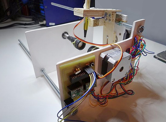
Create the DIY version of Egg-bot running on Arduino

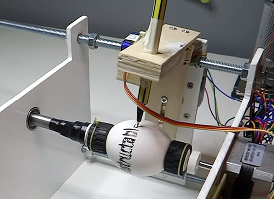
We featured Nikodem’s bike tachometer last September on this blog. He’s now sharing with us another DIY project called DIY Arduino controlled Egg-Bot. It’s a DIY version of the original Egg-bot created by Evil Mad Scientist Laboratories.

You can follow the step-by-step tutorial on Instructables and here’s a preview of the bill of materials you’ll need to make the project at home:

– Stepper motor with 200 steps per revolution (x2)  / I use 12V and 0,33A but you can use other.
– Stepper motor driver A4988 (x2)
Arduino Uno
– Power supply for stepper
– Micro servo
– Plastic plate, wood
– 40cm screws x3 and 12 nuts for it’s
– Two Lego wheels
– Markers in different colors
– Drill, knife, saw, screwdriver, double sided tape, wood glue, wire, soldering iron, rubber bands
– Everything you need to make PCB


Voice Controlled RGB LED Lamp

[Saurabh] wanted a quick project to demonstrate how easy it can be to build devices that are voice controlled. His latest Instructable does just that using an Arduino and Visual Basic .Net.

[Saurabh] decided to build a voice controlled lamp. He knew he wanted it to change colors as well as be energy-efficient. It also had to be easy to control. The obvious choice was to use an RGB LED. The LED on its own wouldn’t be very interesting. He needed something to diffuse the light, like a lampshade. [Saurabh] decided to start with an empty glass jar. He filled the jar with gel wax, which provides a nice surface to diffuse the light.

The RGB LED was mounted underneath the jar’s screw-on cover. [Saurabh] soldered a 220 ohm current limiting resistor to each of the three anodes of the LED. A hole was drilled in the cap so he’d have a place to run the wires. The LED was then hooked up to an Arduino Leonardo.

The Arduino sketch has several built-in functions to set all of the colors, and also fade. [Saurabh] then wrote a control interface using Visual Basic .Net. The interface allows you to directly manipulate the lamp, but it also has built-in voice recognition functionality. This allows [Saurabh] to use his voice to change the color of the lamp, turn it off, or initiate a fading routing. You can watch a video demonstration of the voice controls below.


Filed under: Arduino Hacks, led hacks

Build a Bass Master 3000 Carnival Game

We’ve all been there. You are having fun walking around the carnival when you suddenly find yourself walking past the carnival games. The people working the booths are taunting you, trying to get you to play their games. You know the truth, though. Those games are rigged. You don’t know how they do it. You just know that they do… somehow.

Now you can put your worries to rest and build your own carnival game! [John] built his own “Bass Master 3000” style carnival game and posted an Instructable so you can make one too.

The game is pretty straightforward. You have a giant fish-shaped target with a wide open mouth. You take hold of a small fishing reel with a rubber ball on the end. Your goal is to cast the ball out and hit the fish in its big mouth. If you hit the mouth, you get to hear a loud buzzer and see some flashing lights. The system also uses a webcam to take a candid photo of the winner. A computer screen shows all of the winners of the day.

The brain of the system is an Arduino Yún. The Yún is similar to an Uno but it also has some extra features. Some good examples are an Ethernet port, a wireless adapter, and an SD card slot. The mouth sensors are just two piezo elements. Each sensor is hooked up to the Arduino through a small trim pot. This allows you to dial in the sensitivity of each sensor. The lights and the buzzer are controlled via a relay, triggered by a 5V digital pin on the Arduino.

The Yún actually has a small on-board Linux computer that you can communicate with from inside the Arduino environment. This allows [John] to use the Yún to actually take photos directly from a web cam, store them on the local SD card, and display them on a local web server. The web server runs a simple script that displays a slide show of all of the photos stored on the card.

The final piece of the game is the physical target itself. The target is painted using acrylic paint onto a small tarp. The tarp is then attached to a square frame made from PVC pipe. The mouth of the fish is cut out of the tarp. A large piece of felt is then placed behind the hole with the piezo sensors attached. A short length of copper pipe helps to weigh down the bottom of the felt and keep it in place. The important thing is to make sure the felt isn’t touching the tarp. If it touches, it might be overly sensitive and trigger even when a player misses.

Now you know how to build your own Bass Master 3000 carnival game. Whether you rig the game or not is up to you. Also, be sure to check out a video of the system working below.


Filed under: Arduino Hacks
Hack a Day 28 Jun 12:00

Wireless Controlled Robotic Hand made with Arduino Lilypad

Gabri295 published on Instructable a tutorial for a project created during his last year of high school.  It’s  an artificial hand controlled by a glove with 5 flex sensors and Arduino Lilypad . The artificial hand reproduces the movements of the hand wearing the glove.

The components you need to control glove are:
• an elastic glove;
• Lilypad Arduino board (there are different versions, which usually only have 4 analog inputs, so pay attention and buy the one in the image);
• Shield to connect the Xbee module;
• 5 Flex sensors;
• 5 resistors: 47 K?;
• battery pack with 3×1.5 V batteries (Lilypad can be powered from 2.7 to 5.5 V, so 4.5 V it’s ok);
• LilyPad FTDI adapter (quite optional).

The materials needed for the robotic hand are:

• a steel structure for the palm of the hand and wood for the fingers;
• Arduino UNO board;
• 5 servomotors;
• to connect the servomotors I used the Robot_Shield from FuturaElettronica, which has also a switching regulator to power the entire circuit, but you can use any shield made for that;
• Shield to connect the XBee module (I made an horrible one, but it’s economic and I needed to make it small because of the size of the Robot_Shield, you can buy even XBee shields which have also pins to connect the servomotors);
• fishing wires;
• 9 V Battery.

Below you can take a look at the schematic and then follow the steps to make one yourself!


Arduino Blog 24 Jun 21:46

DIY cyborg appendage is less exciting than it sounds (video)

When we envision our transhumanist future, it's a little more profound than simply adding a sixth finger... but we suppose you've gotta start somewhere. Instructables user and employee Frenzy gave himself a rather primitive extra digit as part of a project for an Electronics and Robotics class at San Francisco State University. Sadly he doesn't provide step-by-step instructions for building your own cyborg appendage, but it doesn't seem too difficult. Frenzy borrowed heavily from other projects, using EMG sensors to trigger a servo controlled by an Arduino, which he strapped to the back of a glove. Like we said, doesn't seem particularly hard, once you figure out how to get the microcontroller to play nice with the sensors. Obviously this is just one small step step for DIY cyborgs. Next, we need to graph on a few extra arms to make one-man liveblogging a much simpler endeavor. To see Primitive Transhumanism #2: Sixth Finger in action, head on past the break.

Continue reading DIY cyborg appendage is less exciting than it sounds (video)

DIY cyborg appendage is less exciting than it sounds (video) originally appeared on Engadget on Fri, 08 Jun 2012 02:32:00 EST. Please see our terms for use of feeds.

Permalink | Email this | Comments