Posts with «i2c» label

The Lightgame Project: A Multiplayer Arduino Game

Summer is upon us. The Lightgame Project is a multiplayer reaction time based game built around the Arduino. It’s a perfect rainy day project for those restless kids (and adults!). Designed by two undergraduate students [Efstathios] and [Thodoris] for a semester long project, all the hard work has already been done for you.

There are tons of reasons we love games that you can build yourself. For one, it’s an amazing way to get children interested in hobby electronics, making, and hacking. Especially when they can play the game with (and show off to) their friends. Another reason is that it is a perfect way to share your project with friends and family, showcasing what you have been learning. The game is based on your reaction time and whether or not you press your button when another players color is shown. The project is built around two Arduinos connected via I2C. The master handles the mechanics of the game, while the slave handles the TFT LCD and playing music through a buzzer.

I2C is a great communication protocol to be familiar with and this is a great project to give it a try. [Efstathios] and [Thodoris] did a great job writing up their post, plus they included all the code and schematics needed to build your own. It would be great to see more university professors foster open source hardware and software with their students. A special thanks goes out to [Dr. Dasygenis] for submitting his student’s work to us!


Filed under: Arduino Hacks
Hack a Day 29 May 03:00

Controlling a Raspberry Pi / Arduino Bot from the Internet Part 2 of 3

This is part two of a three part Series to explain how I control my BotTwo semi-Autonomous Robot from a webpage on the Internet. 

read more

Controlling a Raspberry Pi / Arduino Bot from the Internet Part 2 of 3

This is part two of a three part Series to explain how I control my BotTwo semi-Autonomous Robot from a webpage on the Internet. 

read more

Controlling a Raspberry Pi / Arduino Bot from the Internet Part 1 of 3

This is a three part Series to explain how I control my BotTwo&n

read more

Tutorial – pcDuino GPIO with Arduino IDE

Introduction

In this tutorial we’ll explain how to use the GPIO pins of the Arduino implementation in the pcDuino v2 and v3. As the v3 is now available you can use it as well, and it’s interchangeable with the v2. Although the pcDuino v2 is Arduino-compatible, there are a few differences that you need to be aware of – in order to make your projects a success and also to avoid any costly mistakes.

This tutorial builds on the knowledge from the initial review, so if pcDuino v2 is new to you please review this article before moving on. In this instalment we’ll run through the following:

  • ADC (analogue to digital)
  • Digital input and outputs
  • PWM (pulse-width modulation)
  • I2C bus
  • SPI bus

Using ADC pins

Just like an Arduino Uno or compatible, the pcDuino v2 has six ADC pins, in the expected locations:

Using the pcDuino v2’s ADC pins is quite straight forward, however you just need to remember a few things about the hardware – that the maximum input voltage on A0 and A1 is 2V – and 3.3V for A2~A5.

Although there is an AREF pin on the board, this function isn’t supported at the time of writing. From the software perspective A0 and A1’s values have a 6-bit resolution and can fall between 0 and 63 (0~2V), otherwise the others have a 12-bit resolution and thus return values between 0 and 4095 (0~3.3V). Using the ADC pins is simple, and demonstrated in the following sketch:

// pcDuino v2 ADC demonstration

#include <core.h> // for pcDuino

int a0, a1, a2, a3, a4, a5;

void setup() 
{
}

void loop() 
{
  // read all the ADCs
  a0 = analogRead(0);
  a1 = analogRead(1);
  a2 = analogRead(2);
  a3 = analogRead(3);
  a4 = analogRead(4);
  a5 = analogRead(5);
  // display ADC values to console
  printf(A0, A1,   A2,   A3,   A4,   A5\n);
  printf(%d  %d  %d  %d  %d  %d\n, a0, a1, a2, a3, a4, a5);
  printf(n);
  delay(1000);
}

… which results with the following in the console:

Digital outputs

The pcDuino v2’s implementation of digital outputs aren’t anything out of the ordinary – except that you are limited to a maximum voltage of 3.3V instead of the usual 5V. Furthermore you can only source 4mA from each pin. However if you have some 5V-only shields that you must use with your pcDuino v2 – there is a Voltage Translation board that can be used to solve the problem:

However using 3.3V for new designs shouldn’t be an issue – new sensors, ICs and so on should be 3.3V-compatible. And with the pcDuino v2 you get an extra four digital I/O pins, located next to the SPI grouping as shown below:

These are simply addressed as D14~D17. Now back for a quick demonstration with the typical LEDs. As the current sourced from each GPIO pin cannot exceed 4mA, you need to use a resistor to keep things under control. Using the LED wizard, by entering a 3.3V supply, 2.1V forward voltage for our LEDs and a 4mA current – the resistor value to use is 330Ω.

If you’re having a lazy attack and use 560Ω, the current will be around 2.5mA with acceptable results. We’ve done just that with the following demonstration sketch:

// pcDuino v2 digital output demonstration

#include <core.h> // for pcDuino

void setup() 
{
  pinMode(4, OUTPUT);
  pinMode(5, OUTPUT);
  pinMode(6, OUTPUT);
  pinMode(7, OUTPUT);  
  digitalWrite(4, LOW);  
  digitalWrite(5, LOW);
  digitalWrite(6, LOW);
  digitalWrite(7, LOW);  
}

void loop() 
{
  for (int i = 4; i < 8; i++)
  {
    digitalWrite(i, HIGH);
    delay(250);
    digitalWrite(i, LOW);
  }
}

… and the results in this video.

Digital inputs

When using the digital pins as inputs, just treat them as normal except they have a maximum input voltage of 3.3V for HIGH. Again – just keep thinking “3.3V”.

Using the I2C data bus

The I2C bus (or “two wire interface”) is a common serial data bus used for interfacing all manner of devices with a microcontroller. You can find a background on the I2C bus and Arduino tutorial here. Just like an Arduino Uno R3, the I2C bus pins are both A4 and A5 (for SCL and SDA) and can also be found up near D13, for example.

The limitations for the pcDuino v2’s version of I2C bus are few – the maximum speed is 200 kHz, it only uses 7-bit addresses and you can’t use the pcDuino in slave mode. However there are 2.2kΩ pullup resistors which can save using them with external circuitry.

We demonstrate the I2C bus by writing data to and reading it from a Microchip 24LC256 EEPROM (which is handy in itself as there isn’t any EEPROM function on the pcDuino v2). This is demonstrated with an Arduino Uno in part two of our I2C tutorials.

Connection is very easy – pins 1 to 4 of the EEPROM are connected to GND, pin 5 to SDA, pin 6 to SCL, pin 7 to GND and pin 8 to 3.3V. Finally a 0.1uF capacitor is placed across 3.3V and GND.

The sketch to read and write values to the EEPROM is simple, and apart from the #include <core.h> for the pcDuino all the other functions operate as normal.

// pcDuino I2C demonstration

#include <core.h> // for pcDuino
#include <Wire.h>   for I2C
#define chip1 0x50  device bus address for EEPROM

// always have your values in variables
unsigned int pointer = 69;  // we need this to be unsigned, as you may have an address  32767
byte d=0;  // example variable to handle data going in and out of EERPROMS

void setup()
{
  Wire.begin();  // wake up, I2C!
}

void writeData(int device, unsigned int add, byte data) 
// writes a byte of data 'data' to the chip at I2C address 'device', in memory location 'add'
{
  Wire.beginTransmission(device);
  Wire.write((int)(add  8)); // left-part of pointer address
  Wire.write((int)(add & 0xFF)); // and the right
  Wire.write(data);
  Wire.endTransmission();
  delay(10);
}

byte readData(int device, unsigned int add) 
// reads a byte of data from memory location 'add' in chip at I2C address 'device' 
{
  byte result;  // returned value
  Wire.beginTransmission(device);  // these three lines set the pointer position in the EEPROM
  Wire.write((int)(add  8));  // left-part of pointer address
  Wire.write((int)(add & 0xFF)); // and the right
  Wire.endTransmission();
  Wire.requestFrom(device,1); // now get the byte of data...
  result = Wire.read();
  return result;  // and return it as a result of the function readData
}

void loop()
{
  printf(Writing data...\n);
  for (int a=0; a10; a++)
  {
    writeData(chip1,a,a);
  }
  printf(Reading data...\n);
  for (int a=0; a10; a++)
  {
    d=readData(chip1,a);    
    printf(Pointer %d holds %d.\n,a,d);
  }
}

… which results with the following output in the console:

As you now know, using I2C isn’t hard at all. A lot of beginners shy away from it – or run screaming for the nearest library for their part. You don’t need libraries – spend a little time now learning about I2C and you’re set for life.

Using the SPI data bus

Again we have some SPI tutorials for Arduino, so check them out first if the concept is new to you. Writing to an SPI device with the pcDuino v2 isn’t tricky at all, you have the 3.3V hardware limitation and the SPI pins are in the same location (D10~D13) or in a separate group on the board:

Furthermore the maximum SPI speed is 12 MHz and the pcDuino v2’s  implementation of SPI can only work as a master. However in the sketch there are a few differences to note. To demonstrate this we’ll control a Microchip MCP4162 digital rheostat via SPI to control the brightness of an LED. Here is the circuit:

And now for the sketch. Take note of the fourth line in void setup() –  this is used to set the SPI bus speed to 12 MHz. You can also reduce the speed with other multipliers such as 32, 64 and 128 to slow it down even further. The other point to note is the use of SPI.transfer(). With the pcDuino v2 there are two parameters – the first is the data to send to the SPI device, and the second is either

SPI_CONTINUE

if there is another byte of data following immediately, or

SPI_LAST

if that is the last byte for that immediate transfer. You can see this use of the paramters within the function setValue() in the demonstration sketch below.

// pcDuino SPI demonstration

#include <core.h>  // for pcDuino
#include <SPI.h>
int ss = 10;
int del = 1000;

void setup()
{
  SPI.begin();
  SPI.setDataMode(SPI_MODE3);
  SPI.setBitOrder(MSBFIRST);
  SPI.setClockDivider(SPI_CLOCK_DIV16);
  pinMode(ss, OUTPUT);
  digitalWrite(ss, HIGH);
}

void setValue(int value)
{
  digitalWrite(ss, LOW);
  SPI.transfer(0, SPI_CONTINUE);
  SPI.transfer(value, SPI_LAST);
  digitalWrite(ss, HIGH);
}

void loop()
{
  setValue(255);
  delay(del);
  setValue(223);
  delay(del);
  setValue(191);
  delay(del);
  setValue(159);
  delay(del);
  setValue(127);
  delay(del);
  setValue(95);
  delay(del);
  setValue(63);
  delay(del);
  setValue(31);
  delay(del);
  setValue(0);
  delay(del);
}

When using the SPI bus, relevant data will appear in the console, for example:

And finally the demonstration video to show you it really works – you can see the output voltage from the rheostat and the matching LED brightness.

Receiving data from the SPI bus is equally as simple, however at the time of writing we don’t have an SPI device to demonstrate this, so please refer the SPI part of the pcDuino guide. Finally, you can’t use PWM on D10 or D11 when using the SPI bus in your sketch.

Pulse-width modulation

You can simulate analogue output using PWM with a pcDuino v2 – however there are two types of PWM pins available. The first is found on digital pins D3, D9, D10 and D11 – they are simulated PWM – and have a low range of zero to twenty at 5 Hz. There are two hardware PWM pins – D5 and D6, which  run at 520Hz and have the full range of 0~255 available in analogWrite(). Once again – they output 3.3V. Furthermore, you can’t use pinMode() functions or the SPI bus if using D10 and/or D11 for PWM.

Conclusion

Now you should have an understanding of the features and limitations of using GPIO pins with your pcDuino v2 Arduino sketches. And finally a plug for my own store – tronixlabs.com – offering a growing range and Australia’s best value for supported hobbyist electronics from adafruit, DFRobot, Freetronics, Seeed Studio and much more.

Have fun and keep checking into tronixstuff.com. Why not follow things on twitterGoogle+, subscribe  for email updates or RSS using the links on the right-hand column, or join our forum – dedicated to the projects and related items on this website.

The post Tutorial – pcDuino GPIO with Arduino IDE appeared first on tronixstuff.

Tronixstuff 29 Jan 04:12
adc  arduino  gpio  i2c  input  output  pcduino  pwm  review  spi  tronixlabs  tronixstuff  tutorial  

Tutorial – Arduino and PCF8563 real time clock IC

Use the NXP PCF8563 real-time clock IC with Arduino in chapter fifty-four of our Arduino Tutorials. The first chapter is here, the complete series is detailed here.

Updated 20/08/2013

Introduction

Recently a few people have been asking about the PCF8563 real-time clock IC from NXP – so this is a tutorial on how to use it for time, date, alarm clock and square-wave generation purposes.

The PCF8563 is another inexpensive RTC that can be used with an Arduino or other platforms due to the wide operating voltage (1 to 5.5V DC), I2C interface, and very low power consumption (when powered by a backup battery it only draws 0.25 μA). If you aren’t up to speed on the I2C interface, please review the I2C tutorials before moving forward. And please download the data sheet (.pdf).

The PCF8563 is available in various chip packages, for the curious we’re using the TSSOP8 version mounted on a breakout board:

Don’t panic – you can also get it in a breadboard-friendly DIP (through-hole) package as well, and also on a pre-built module from the usual suspects.

Demonstration Circuit

If you have a pre-made module, you can skip to the next section. However if you’re making up the circuit yourself, you will need:

  • One 32.768 kHz crystal
  • Two 1N4148 diodes*
  • One 3V coin cell (with holder)*
  • Two 10kΩ resistors
  • One 0.1 uF capacitor

And here’s the schematic:

* You can skip the diodes and battery if you don’t want a backup power supply when the main power is turned off or removed. Pin 3 is for the interrupt output (we’ll consider that later) and pin 7 is for the square-wave oscillator output.

Communicating with the PCF8563

Now to get down into the land of I2C once more. When looking through the data sheet NXP mentions two bus addresses, which have the same 7-bits finished with either a 1 for read or 0 for write. However you can just bitshift it over one bit as we don’t need the R/W bit – which gives you a bus address of 0x51.

Next you need to know which registers store the time and date – check the register map (table 4) on page 7 of the data sheet:

 There will be a few other registers of interest, but we’ll return to those later. For now, note that the time and date start from 0x02. And one more thing – data is stored in the BCD (binary-coded- decimal) format. But don’t panic, we have a couple of functions to convert numbers between BCD and decimal.

Writing the time and date is a simple matter of collating the seconds, minutes, hours, day of week, day of month, month and year into bytes, converting to BCD then sending them to the PCF8563 with seven Wire.write() functions. Reading the data is also easy, just set the pointer to 0x02 and request seven bytes of data – then run them through a BCD to decimal conversion. With a catch.

And that catch is the need to sort out unwanted bits. Revisit table 4 in the data sheet – if you see an x that’s an unused bit. If any of them are a 1 they will mess up the BCD-decimal conversion when reading the register, so they need to be eliminated just like a whack-a-mole. To do this, we perform an & (bitwise AND) operation on the returned byte and mask out the unwanted bits with a zero. How does that work?

Example – the byte for dayOfMonth is returned – we only need bits 5 to 0. So 6 and 7 are superfluous. If you use (dayOfMonth & B00111111) the & function will set bits 6 and 7 to zero, and leave the other bits as they were.

Now to put all that together in a demonstration sketch. It puts everything mentioned to work and simply sets the time to the PCF8563, and then returns it to the serial monitor. The data is kept in global variables declared at the start of the sketch, and the conversions between BCD and decimal are done “on the fly” in the functions used to send or retrieve data from the PCF8563. Read through the following sketch and see how it works for yourself:

// Example 54.1 - PCF8563 RTC write/read demonstration

#include "Wire.h"
#define PCF8563address 0x51

byte second, minute, hour, dayOfWeek, dayOfMonth, month, year;
String days[] = {"Sunday", "Monday", "Tuesday", "Wednesday", "Thursday", "Friday", "Saturday" };

byte bcdToDec(byte value)
{
  return ((value / 16) * 10 + value % 16);
}

byte decToBcd(byte value){
  return (value / 10 * 16 + value % 10);
}

void setPCF8563()
// this sets the time and date to the PCF8563
{
  Wire.beginTransmission(PCF8563address);
  Wire.write(0x02);
  Wire.write(decToBcd(second));  
  Wire.write(decToBcd(minute));
  Wire.write(decToBcd(hour));     
  Wire.write(decToBcd(dayOfMonth));
  Wire.write(decToBcd(dayOfWeek));  
  Wire.write(decToBcd(month));
  Wire.write(decToBcd(year));
  Wire.endTransmission();
}

void readPCF8563()
// this gets the time and date from the PCF8563
{
  Wire.beginTransmission(PCF8563address);
  Wire.write(0x02);
  Wire.endTransmission();
  Wire.requestFrom(PCF8563address, 7);
  second     = bcdToDec(Wire.read() & B01111111); // remove VL error bit
  minute     = bcdToDec(Wire.read() & B01111111); // remove unwanted bits from MSB
  hour       = bcdToDec(Wire.read() & B00111111); 
  dayOfMonth = bcdToDec(Wire.read() & B00111111);
  dayOfWeek  = bcdToDec(Wire.read() & B00000111);  
  month      = bcdToDec(Wire.read() & B00011111);  // remove century bit, 1999 is over
  year       = bcdToDec(Wire.read());
}

void setup()
{
  Wire.begin();
  Serial.begin(9600);
  // change the following to set your initial time
  second = 0;
  minute = 28;
  hour = 9;
  dayOfWeek = 2;
  dayOfMonth = 13;
  month = 8;
  year = 13;
  // comment out the next line and upload again to set and keep the time from resetting every reset
  setPCF8563();
}

void loop()
{
  readPCF8563();
  Serial.print(days[dayOfWeek]); 
  Serial.print(" ");  
  Serial.print(dayOfMonth, DEC);
  Serial.print("/");
  Serial.print(month, DEC);
  Serial.print("/20");
  Serial.print(year, DEC);
  Serial.print(" - ");
  Serial.print(hour, DEC);
  Serial.print(":");
  if (minute < 10)
  {
    Serial.print("0");
  }
  Serial.print(minute, DEC);
  Serial.print(":");  
  if (second < 10)
  {
    Serial.print("0");
  }  
  Serial.println(second, DEC);  
  delay(1000);
}

And a quick video of this in operation:

If all you need to do is write and read the time with the PCF8563, you’re ready to go. However there’s a few more features of this unassuming little part which you might find useful, so at least keep reading…

Square-wave output

As with any clock or RTC IC, an oscillator is involved, and as mentioned earlier you can take this from pin 7 of the PCF8563. However – it’s an open-drain output – which means current flows from the supply voltage into pin 7. For example if you want to blink an LED, connect a 560Ω resistor between 5V and the anode of the LED, then connect the cathode to pin 7 of the PCF8563.

The frequency is controlled from the register at 0x0D. Simply write one of the following values for the respective frequencies:

  • 10000000 for 32.768 kHz;
  • 10000001 for 1.024 kHz;
  • 10000010 for 32 kHz;
  • 10000011 for 1 Hz;
  • 0 turns the output off and sets it to high impedance.

The following is a quick demonstration sketch which runs through the options:

// Example 54.2 - PCF8563 square-wave generator (signal from pin 7)

#include "Wire.h"
#define PCF8563address 0x51

void PCF8563oscOFF()
// turns off oscillator
{
  Wire.beginTransmission(PCF8563address);
  Wire.write(0x0D);
  Wire.write(0);
  Wire.endTransmission();
}

void PCF8563osc1Hz()
// sets oscillator to 1 Hz
{
  Wire.beginTransmission(PCF8563address);
  Wire.write(0x0D);
  Wire.write(B10000011);
  Wire.endTransmission();
}

void PCF8563osc32Hz()
// sets oscillator to 32 kHz
{
  Wire.beginTransmission(PCF8563address);
  Wire.write(0x0D);
  Wire.write(B10000010);
  Wire.endTransmission();
}

void PCF8563osc1024kHz()
// sets oscillator to 1.024 kHz
{
  Wire.beginTransmission(PCF8563address);
  Wire.write(0x0D);
  Wire.write(B10000001);
  Wire.endTransmission();
}

void PCF8563osc32768kHz()
// sets oscillator to 32.768 kHz
{
  Wire.beginTransmission(PCF8563address);
  Wire.write(0x0D);
  Wire.write(B10000000);
  Wire.endTransmission();
}

void setup()
{
  Wire.begin();
}

void loop()
{
  PCF8563osc1Hz();
  delay(2000);
  PCF8563osc32Hz();
  delay(2000);
  PCF8563osc1024kHz();
  delay(2000);
  PCF8563osc32768kHz();
  delay(2000);
  PCF8563oscOFF();
  delay(2000);
}

And the resulting waveforms from slowest to highest frequency. Note the sample was measured from a point between the LED and resistor, so the oscillations don’t vary between the supply voltage and zero:

Self-awareness of clock accuracy

The PCF8563 monitors the oscillator and supply voltage, and if the oscillator stops or the voltage drops below a certain point – the first bit of the seconds register (called the VL bit) is set to 1. Thus your sketch can tell you if there’s a chance of the time not being accurate by reading this bit. The default value is 1 on power-up, so you need to set it back to zero after setting the time in your sketch – which is done when you write seconds using the code in our example sketches. Then from that point it can be monitored by reading the seconds register, isolating the bit and returning the value.

Examine the function checkVLerror() in the following example sketch. It reads the seconds byte, isolates the VL bit, then turns on D13 (the onboard LED) if there’s a problem. The only way to restore the error bit to “OK” is to re-set the time:

// Example 54.3 - PCF8563 RTC write/read demonstration with error-checking

#include "Wire.h"
#define PCF8563address 0x51

byte second, minute, hour, dayOfWeek, dayOfMonth, month, year;
String days[] = {"Sunday", "Monday", "Tuesday", "Wednesday", "Thursday", "Friday", "Saturday" };

byte bcdToDec(byte value)
{
  return ((value / 16) * 10 + value % 16);
}

byte decToBcd(byte value){
  return (value / 10 * 16 + value % 10);
}

void setPCF8563()
// this sets the time and date to the PCF8563
{
  Wire.beginTransmission(PCF8563address);
  Wire.write(0x02);
  Wire.write(decToBcd(second));  
  Wire.write(decToBcd(minute));
  Wire.write(decToBcd(hour));     
  Wire.write(decToBcd(dayOfMonth));
  Wire.write(decToBcd(dayOfWeek));  
  Wire.write(decToBcd(month));
  Wire.write(decToBcd(year));
  Wire.endTransmission();
}

void readPCF8563()
// this gets the time and date from the PCF8563
{
  Wire.beginTransmission(PCF8563address);
  Wire.write(0x02);
  Wire.endTransmission();
  Wire.requestFrom(PCF8563address, 7);
  second     = bcdToDec(Wire.read() & B01111111); // remove VL error bit
  minute     = bcdToDec(Wire.read() & B01111111); // remove unwanted bits from MSB
  hour       = bcdToDec(Wire.read() & B00111111); 
  dayOfMonth = bcdToDec(Wire.read() & B00111111);
  dayOfWeek  = bcdToDec(Wire.read() & B00000111);  
  month      = bcdToDec(Wire.read() & B00011111);  // remove century bit, 1999 is over
  year       = bcdToDec(Wire.read());
}

void checkVLerror()
// this checks the VL bit in the seconds register
// and turns on D13 if there's a possible accuracy error
{
  byte test;
  Wire.beginTransmission(PCF8563address);
  Wire.write(0x02);
  Wire.endTransmission();
  Wire.requestFrom(PCF8563address, 1);
  test = Wire.read(); 
  test = test & B10000000;
  if (test == B10000000)
  {
    // error
    digitalWrite(13, HIGH);
    Serial.println("Uh-oh - possible accuracy error");
  } else 
  if (test != B10000000)
  {
    digitalWrite(13, LOW);
  }
}

void setup()
{
  Wire.begin();
  pinMode(13, OUTPUT);
  digitalWrite(13, HIGH);
  Serial.begin(9600);
  // change the following to set your inital time
  second = 0;
  minute = 42;
  hour = 11;
  dayOfWeek = 2;
  dayOfMonth = 13;
  month = 8;
  year = 13;
  // comment out the next line and upload again to set and keep the time from resetting every reset
  // setPCF8563();
}

void loop()
{
  readPCF8563();
  Serial.print(days[dayOfWeek]); 
  Serial.print(" ");  
  Serial.print(dayOfMonth, DEC);
  Serial.print("/");
  Serial.print(month, DEC);
  Serial.print("/20");
  Serial.print(year, DEC);
  Serial.print(" - ");
  Serial.print(hour, DEC);
  Serial.print(":");
  if (minute < 10)
  {
    Serial.print("0");
  }
  Serial.print(minute, DEC);
  Serial.print(":");  
  if (second < 10)
  {
    Serial.print("0");
  }  
  Serial.println(second, DEC);  
  checkVLerror();
  delay(1000);
}

And now for a demonstration of the error-checking at work. We have the PCF8563 happily returning the data to the serial monitor. Then the power is removed and restored. You see D13 on the Arduino-compatible board turn on and then the error is displayed in the serial monitor:

This function may sound frivolous, however if you’re building a real product or serious project using the PCF8563, you can use this feature to add a level of professionalism and instil confidence in the end user.

Alarm Clock

You can use the PCF8563 as an alarm clock, that is be notified of a certain time, day and/or day of the week – at which point an action can take place. For example, trigger an interrupt or turn on a digital output pin for an external siren. Etcetera. Using the alarm in the sketch is quite similar to reading and writing the time, the data is stored in certain registers – as shown in the following table from page seven of the data sheet:

However there is a catch – the MSB (most significant bit, 7) in the registers above is used to determine whether that particular register plays a part in the alarm. For example, if you want your alarm to include hours and minutes, bit 7 needs to be set to 1 for the hour and minute alarm register. Don’t panic – you can easily set that bit by using a bitwise OR (“|”) and B10000000 to set the bit on with the matching data before writing it to the register.

Checking if the alarm has occurred can be done with two methods – software and hardware. Using software you check bit 3 of the register at 0x01 (the “AF” alarm flag bit). If it’s 1 – it’s alarm time! Then you can turn the alarm off by setting that bit to zero. Using hardware, first set bit 1 of register 0x01 to 1 – then whenever an alarm occurs, current can flow into pin 3 of the PCF8563. Yes – it’s an open-drain output – which means current flows from the supply voltage into pin 3. For example if you want to turn on an LED, connect a 560Ω resistor between 5V and the anode of the LED, then connect the cathode to pin 3 of the PCF8563. To turn off this current, you need to turn off the alarm flag bit as mentioned earlier.

Now let’s put all that into a demonstration sketch. It’s documented and if you’ve been following along it shouldn’t be difficult at all:

// Example 54.4 - PCF8563 alarm clock demonstration

#include "Wire.h"
#define PCF8563address 0x51

byte second, minute, hour, dayOfWeek, dayOfMonth, month, year;
byte alarmMinute, alarmHour, alarmDay, alarmDayOfWeek;
String days[] = {"Sunday", "Monday", "Tuesday", "Wednesday", "Thursday", "Friday", "Saturday" };

byte bcdToDec(byte value)
{
  return ((value / 16) * 10 + value % 16);
}

byte decToBcd(byte value){
  return (value / 10 * 16 + value % 10);
}

void setPCF8563alarm()
// this sets the alarm data to the PCF8563
{
  byte am, ah, ad, adow;
  am = decToBcd(alarmMinute);
  am = am | 100000000; // set minute enable bit to on
  ah = decToBcd(alarmHour);
  ah = ah | 100000000; // set hour enable bit to on
  ad = decToBcd(alarmDay);
  ad = ad | 100000000; // set day of week alarm enable bit on
  adow = decToBcd(alarmDayOfWeek);
  adow = ad | 100000000; // set day of week alarm enable bit on

  // write alarm data to PCF8563
  Wire.beginTransmission(PCF8563address);
  Wire.write(0x09);
  Wire.write(am);  
  Wire.write(ah);

  // optional day of month and day of week (0~6 Sunday - Saturday)
  /*
  Wire.write(ad);
  Wire.write(adow);  
  */
  Wire.endTransmission();

  // optional - turns on INT_ pin when alarm activated  
  // will turn off once you run void PCF8563alarmOff()
  Wire.beginTransmission(PCF8563address);
  Wire.write(0x01);
  Wire.write(B00000010);
  Wire.endTransmission();
}

void PCF8563alarmOff()
// turns off alarm enable bits and wipes alarm registers. 
{
  byte test;
  // first retrieve the value of control register 2
  Wire.beginTransmission(PCF8563address);
  Wire.write(0x01);
  Wire.endTransmission();
  Wire.requestFrom(PCF8563address, 1);
  test = Wire.read();

  // set bit 3 "alarm flag" to 0
  test = test - B00001000;

  // now write new control register 2  
  Wire.beginTransmission(PCF8563address);
  Wire.write(0x01);
  Wire.write(test);
  Wire.endTransmission();
}

void checkPCF8563alarm()
// checks if the alarm has been activated
{
  byte test;
  // get the contents from control register #2 and place in byte test;
  Wire.beginTransmission(PCF8563address);
  Wire.write(0x01);
  Wire.endTransmission();
  Wire.requestFrom(PCF8563address, 1);
  test = Wire.read();
  test = test & B00001000; // isolate the alarm flag bit
  if (test == B00001000) // alarm on?
  {
    // alarm! Do something to tell the user
    Serial.println("** alarm **");
    delay(2000);

    // turn off the alarm
    PCF8563alarmOff();
  }
}

void setPCF8563()
// this sets the time and date to the PCF8563
{
  Wire.beginTransmission(PCF8563address);
  Wire.write(0x02);
  Wire.write(decToBcd(second));  
  Wire.write(decToBcd(minute));
  Wire.write(decToBcd(hour));     
  Wire.write(decToBcd(dayOfMonth));
  Wire.write(decToBcd(dayOfWeek));  
  Wire.write(decToBcd(month));
  Wire.write(decToBcd(year));
  Wire.endTransmission();
}

void readPCF8563()
// this gets the time and date from the PCF8563
{
  Wire.beginTransmission(PCF8563address);
  Wire.write(0x02);
  Wire.endTransmission();
  Wire.requestFrom(PCF8563address, 7);
  second     = bcdToDec(Wire.read() & B01111111); // remove VL error bit
  minute     = bcdToDec(Wire.read() & B01111111); // remove unwanted bits from MSB
  hour       = bcdToDec(Wire.read() & B00111111); 
  dayOfMonth = bcdToDec(Wire.read() & B00111111);
  dayOfWeek  = bcdToDec(Wire.read() & B00000111);  
  month      = bcdToDec(Wire.read() & B00011111);  // remove century bit, 1999 is over
  year       = bcdToDec(Wire.read());
}

void setup()
{
  Wire.begin();
  Serial.begin(9600);
  // change the following to set your initial time
  second = 50;
  minute = 44;
  hour = 13;
  dayOfWeek = 1;
  dayOfMonth = 19;
  month = 8;
  year = 13;
  // comment out the next line and upload again to set and keep the time from resetting every reset
  setPCF8563();

  alarmMinute = 45;
  alarmHour = 13;
  // comment out the next line and upload again to set and keep the alarm from resetting every reset  
  setPCF8563alarm();
}

void loop()
{
  readPCF8563();
  Serial.print(days[dayOfWeek]); 
  Serial.print(" ");  
  Serial.print(dayOfMonth, DEC);
  Serial.print("/");
  Serial.print(month, DEC);
  Serial.print("/20");
  Serial.print(year, DEC);
  Serial.print(" - ");
  Serial.print(hour, DEC);
  Serial.print(":");
  if (minute < 10)
  {
    Serial.print("0");
  }
  Serial.print(minute, DEC);
  Serial.print(":");  
  if (second < 10)
  {
    Serial.print("0");
  }  
  Serial.println(second, DEC);  
  delay(1000);

  // alarm?
  checkPCF8563alarm();
}

This is the same as the example 54.1, however we’ve added the required functions to use the alarm. The required alarm data is stored in the global bytes:

byte alarmMinute, alarmHour, alarmDay, alarmDayOfWeek;

and is written to the PCF8563 using the function:

void setPCF8563alarm()

Note the use of bitwise OR (“|”) to add the enable bit 7 to the data before writing to the register. The interrupt pin is also set to activate at the end of this function, however you can remove that part of the code if unnecessary. We also demonstrate checking the alarm status via software using the function:

void checkPCF8563alarm()

which simply reads the AF bit in the register at 0x01 and let’s us know if the alarm has occurred via the Serial Monitor. In this function you can add code to take action for your required needs. It also calls the function:

void PCF8563alarmOff()

which retrieves the contents of the register at 0x01, sets the AF bit to zero and writes it back. We do this to preserve the status of the other bits in that register. For the curious and non-believers you can see this sketch in action through the following video, first the software and then the hardware interrupt pin method (an LED comes on at the alarm time and is then turned off:

Conclusion

Hopefully you found this tutorial useful and now have the confidence to use the PCF8563 in your own projects. Furthermore I hope you learned something about the I2C bus and can have satisfaction in that you didn’t take the lazy option of using the library. People often say to me “Oh, there’s a library for that”, however if you used every library – you’d never learn how to interface things for yourself. One day there might not be a library! And then where would you be? So learning the hard way is better for you in the long run.

And if you enjoy my tutorials, or want to introduce someone else to the interesting world of Arduino – check out my book (now in a second printing) “Arduino Workshop” from No Starch Press.

In the meanwhile have fun and keep checking into tronixstuff.com. Why not follow things on twitterGoogle+, subscribe  for email updates or RSS using the links on the right-hand column? And join our friendly Google Group – dedicated to the projects and related items on this website. Sign up – it’s free, helpful to each other –  and we can all learn something.

The post Tutorial – Arduino and PCF8563 real time clock IC appeared first on tronixstuff.

Tronixstuff 13 Aug 03:18
arduino  clock  i2c  ic  nxp  pcf8563  real  real time clock  rtc  time  tronixstuff  tutorial  

Tutorial – Arduino and the TI ADS1110 16-bit ADC

Learn how to use the TI ADS1110 16-bit ADC with Arduino in chapter fifty-three of my Arduino Tutorials. The first chapter is here, the complete series is detailed here.

Updated 02/07/2013

Introduction

Moving on from the last chapter where we explained an 8-bit ADC, in this instalment we have the Texas Instruments ADS1110 – an incredibly tiny but useful 16-bit analogue-to-digital converter IC.  It can operate between 2.7 and 5.5 V so it’s also fine for Arduino Due and other lower-voltage development boards. This is a quick guide to get you going with the ADS1110 ready for further applications. Before continuing any further, please download the data sheet (pdf) as it will be useful and referred to during this tutorial. The ADS1110 gives you the option of a more accurate ADC than offered by the Arduino’s 10-bit ADCs – and it’s relatively easy to use. The only block for some is the package type – it’s only available in SOT23-6:

So unless you’re making a customised PCB, some sort of breakout will be required. One useful example is the Schmartboard we reviewed earlier:

The ADS1110 uses the I2C bus for communication, so if this is new to you – please review the I2C tutorials before continuing. And as there’s only six pins you can’t set the bus address – instead, you can select from six variants of the ADS1110 – each with their own address (see page two of the data sheet). As you can see the in the photo above, ours is marked “EDO” which matches to the bus address 1001000 or 0x48h. And with the example circuits we’ve used 10kΩ pull-up resistors on the I2C bus. You can use the ADS1110 as either a single-ended or differential ADC –  But first we need to examine the configuration register which is used to control various attributes, and the data register.

Configuration register

Turn to page eleven of the data sheet. The configuration register is one byte in size, and as the ADS1110 resets on a power-cycle – you need to reset the register if your needs are different to the defaults. The data sheet spells it out quite neatly… bits 0 and 1 determine the gain setting for the PGA (programmable gain amplifier). If you’re just measuring voltages or experimenting, leave these as zero for a gain of 1V/V. Next, the data rate for the ADS1110 is controlled with bits 2 and 3. If you have continuous sampling turned on, this determines the number of samples per second taken by the ADC.

After some experimenting with an Arduino Uno we found the values returned from the ADC were a bit off when using the fastest rate, so leave it as 15 SPS unless required otherwise. Bit 4 sets either continuous sampling (0) or one-off sampling (1). Ignore bits 5 and 6, however they’re always set as 0. Finally bit 7 – if you’re in one-off sampling mode, setting it to 1 requests a sample – and reading it will tell you if the returned data is new (0) or old (1). You can check that the value measured is a new value – if the first bit of the configuration byte that comes after the data is 0, it’s new. If it returns 1 the ADC conversion hasn’t finished.

Data register

As the ADS1110 is a 16-bit ADC, it returns the data over two bytes – and then follows with the value of the configuration register. So if you request three bytes the whole lot comes back. The data is in “two’s complement” form, which is a method of using signed numbers with binary. Converting those two bytes is done by some simple maths. When sampling at 15 SPS, the value returned by the ADS1110 (not the voltage)  falls between -32768 and 32767. The higher byte of the value is multiplied by 256, then added to the lower byte – which is then multiplied by 2.048 and finally divided by 32768. Don’t panic, as we do this in the example sketch below.

Single-ended ADC mode

In this mode you can read a voltage that falls between zero and 2.048 V (which also happens to be the inbuilt reference voltage for the ADS1110). The example circuit is simple (from the data sheet):

Don’t forget the 10kΩ pull-up resistors on the I2C bus. The following sketch uses the ADS1110 in the default mode, and simply returns the voltage measured:

// Example 53.1 - ADS1110 single-sided voltmeter (0~2.048VDC)

#include "Wire.h"
#define ads1110 0x48
float voltage, data;
byte highbyte, lowbyte, configRegister;
void setup()
{
 Serial.begin(9600);
 Wire.begin();
}
void loop()
{
 Wire.requestFrom(ads1110, 3);
 while(Wire.available()) // ensure all the data comes in
 {
 highbyte = Wire.read(); // high byte * B11111111
 lowbyte = Wire.read(); // low byte
 configRegister = Wire.read();
 }

 data = highbyte * 256;
 data = data + lowbyte;
 Serial.print("Data >> ");
 Serial.println(data, DEC);
 Serial.print("Voltage >> ");
 voltage = data * 2.048 ;
 voltage = voltage / 32768.0;
 Serial.print(voltage, DEC);
 Serial.println(" V");
 delay(1000);
}

Once uploaded, connect the signal to measure and open the serial monitor – you’ll be presented with something similar to:

If you need to alter the gain of the internal programmable gain amplifier of the ADC – you’ll need to write a new byte into the configuration register using:

Wire.beginTransmission(ads1110);
Wire.write(configuration byte); 
Wire.endTransmission();

before requesting the ADC data. This would be 0x8D, 0x8E or 0x8F for gain values of 2, 4 and 8 respectively – and use 0x8C to reset the ADS1110 back to default.

Differential ADC mode

In this mode you can read the difference between two voltages that each fall between zero and 5 V. The example circuit is simple (from the data sheet):

We must note here (and in the data sheet) that the ADS1110 can’t accept negative voltages on either of the inputs. You can use the previous sketch for the same results – and the resulting voltage will be the value of Vin- subtracted from Vin+. For example, if you had 2 V on Vin+ and 1 V on Vin- the resulting voltage would be 1 V (with the gain set to 1).

Conclusion

Once again I hope you found this of interest, and possibly useful. And if you enjoy my tutorials, or want to introduce someone else to the interesting world of Arduino – check out my new book “Arduino Workshop” from No Starch Press.

In the meanwhile have fun and keep checking into tronixstuff.com. Why not follow things on twitterGoogle+, subscribe  for email updates or RSS using the links on the right-hand column? And join our friendly Google Group – dedicated to the projects and related items on this website. Sign up – it’s free, helpful to each other –  and we can all learn something.

The post Tutorial – Arduino and the TI ADS1110 16-bit ADC appeared first on tronixstuff.

Tronixstuff 02 Jul 09:06

Tutorial – Arduino and PCF8591 ADC DAC IC

Learn how to use the NXP PCF 8591 8-bit A/D and D/A IC with Arduino in chapter fifty-two of my Arduino Tutorials. The first chapter is here, the complete series is detailed here.

Updated 17/06/2013

Introduction

Have you ever wanted more analogue input pins on your Arduino project, but not wanted to fork out for a Mega? Or would you like to generate analogue signals? Then check out the subject of our tutorial – the NXP PCF8591 IC. It solves both these problems as it has a single DAC (digital to analogue) converter as well as four ADCs (analogue to digital converters) – all accessible via the I2C bus. If the I2C bus is new to you, please familiarise yourself with the readings here before moving forward.

The PCF8591 is available in DIP form, which makes it easy to experiment with:
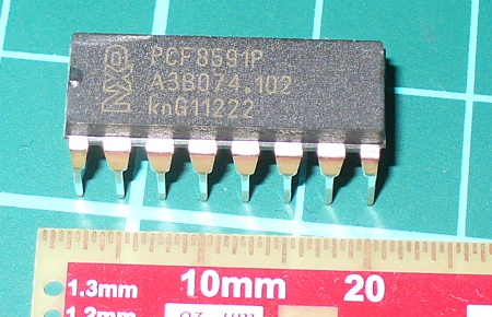
You can get them from the usual retailers. Before moving on, download the data sheet. The PCF8591 can operate on both 5V and 3.3V so if you’re using an Arduino Due, Raspberry Pi or other 3.3 V development board you’re fine. Now we’ll first explain the DAC, then the ADCs.

Using the DAC (digital-to-analogue converter)

The DAC on the PCF8591 has a resolution of 8-bits – so it can generate a theoretical signal of between zero volts and the reference voltage (Vref) in 255 steps. For demonstration purposes we’ll use a Vref of 5V, and you can use a lower Vref such as 3.3V or whatever you wish the maximum value to be … however it must be less than the supply voltage. Note that when there is a load on the analogue output (a real-world situation), the maximum output voltage will drop – the data sheet (which you downloaded) shows a 10% drop for a 10kΩ load. Now for our demonstration circuit:
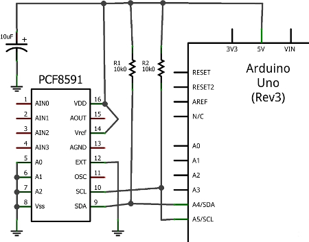
Note the use of 10kΩ pull-up resistors on the I2C bus, and the 10μF capacitor between 5V and GND. The I2C bus address is set by a combination of pins A0~A2, and with them all to GND the address is 0x90. The analogue output can be taken from pin 15 (and there’s a seperate analogue GND on pin 13. Also, connect pin 13 to GND, and circuit GND to Arduino GND.

To control the DAC we need to send two bytes of data. The first is the control byte, which simply activates the DAC and is 1000000 (or 0x40) and the next byte is the value between 0 and 255 (the output level). This is demonstrated in the following sketch:

// Example 52.1 PCF8591 DAC demo
// http://tronixstuff.com/tutorials Chapter 52
// John Boxall June 2013
#include "Wire.h"
#define PCF8591 (0x90 >> 1) // I2C bus address
void setup()
{
 Wire.begin();
}
void loop()
{
 for (int i=0; i<256; i++)
 {
 Wire.beginTransmission(PCF8591); // wake up PCF8591
 Wire.write(0x40); // control byte - turn on DAC (binary 1000000)
 Wire.write(i); // value to send to DAC
 Wire.endTransmission(); // end tranmission
 }

 for (int i=255; i>=0; --i)
 {
 Wire.beginTransmission(PCF8591); // wake up PCF8591
 Wire.write(0x40); // control byte - turn on DAC (binary 1000000)
 Wire.write(i); // value to send to DAC
 Wire.endTransmission(); // end tranmission
 }
}

Did you notice the bit shift of the bus address in the #define statement? Arduino sends 7-bit addresses but the PCF8591 wants an 8-bit, so we shift the byte over by one bit. 

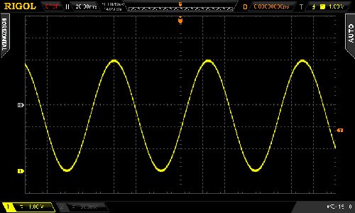
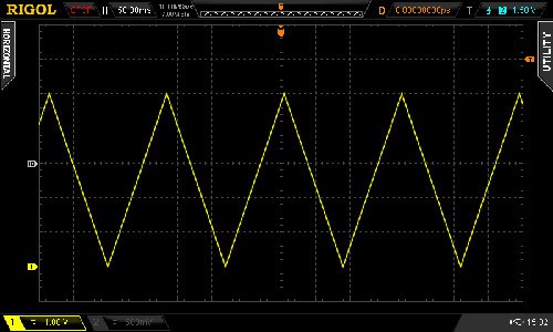
The results of the sketch are shown below, we’ve connected the Vref to 5V and the oscilloscope probe and GND to the analogue output and GND respectively:
If you like curves you can generate sine waves with the sketch below. It uses a lookup table in an array which contains the necessary pre-calculated data points:

// Example 52.2 PCF8591 DAC demo - sine wave
// http://tronixstuff.com/tutorials Chapter 52
// John Boxall June 2013

#include "Wire.h"
#define PCF8591 (0x90 >> 1) // I2C bus address

uint8_t sine_wave[256] = {
 0x80, 0x83, 0x86, 0x89, 0x8C, 0x90, 0x93, 0x96,
 0x99, 0x9C, 0x9F, 0xA2, 0xA5, 0xA8, 0xAB, 0xAE,
 0xB1, 0xB3, 0xB6, 0xB9, 0xBC, 0xBF, 0xC1, 0xC4,
 0xC7, 0xC9, 0xCC, 0xCE, 0xD1, 0xD3, 0xD5, 0xD8,
 0xDA, 0xDC, 0xDE, 0xE0, 0xE2, 0xE4, 0xE6, 0xE8,
 0xEA, 0xEB, 0xED, 0xEF, 0xF0, 0xF1, 0xF3, 0xF4,
 0xF5, 0xF6, 0xF8, 0xF9, 0xFA, 0xFA, 0xFB, 0xFC,
 0xFD, 0xFD, 0xFE, 0xFE, 0xFE, 0xFF, 0xFF, 0xFF,
 0xFF, 0xFF, 0xFF, 0xFF, 0xFE, 0xFE, 0xFE, 0xFD,
 0xFD, 0xFC, 0xFB, 0xFA, 0xFA, 0xF9, 0xF8, 0xF6,
 0xF5, 0xF4, 0xF3, 0xF1, 0xF0, 0xEF, 0xED, 0xEB,
 0xEA, 0xE8, 0xE6, 0xE4, 0xE2, 0xE0, 0xDE, 0xDC,
 0xDA, 0xD8, 0xD5, 0xD3, 0xD1, 0xCE, 0xCC, 0xC9,
 0xC7, 0xC4, 0xC1, 0xBF, 0xBC, 0xB9, 0xB6, 0xB3,
 0xB1, 0xAE, 0xAB, 0xA8, 0xA5, 0xA2, 0x9F, 0x9C,
 0x99, 0x96, 0x93, 0x90, 0x8C, 0x89, 0x86, 0x83,
 0x80, 0x7D, 0x7A, 0x77, 0x74, 0x70, 0x6D, 0x6A,
 0x67, 0x64, 0x61, 0x5E, 0x5B, 0x58, 0x55, 0x52,
 0x4F, 0x4D, 0x4A, 0x47, 0x44, 0x41, 0x3F, 0x3C,
 0x39, 0x37, 0x34, 0x32, 0x2F, 0x2D, 0x2B, 0x28,
 0x26, 0x24, 0x22, 0x20, 0x1E, 0x1C, 0x1A, 0x18,
 0x16, 0x15, 0x13, 0x11, 0x10, 0x0F, 0x0D, 0x0C,
 0x0B, 0x0A, 0x08, 0x07, 0x06, 0x06, 0x05, 0x04,
 0x03, 0x03, 0x02, 0x02, 0x02, 0x01, 0x01, 0x01,
 0x01, 0x01, 0x01, 0x01, 0x02, 0x02, 0x02, 0x03,
 0x03, 0x04, 0x05, 0x06, 0x06, 0x07, 0x08, 0x0A,
 0x0B, 0x0C, 0x0D, 0x0F, 0x10, 0x11, 0x13, 0x15,
 0x16, 0x18, 0x1A, 0x1C, 0x1E, 0x20, 0x22, 0x24,
 0x26, 0x28, 0x2B, 0x2D, 0x2F, 0x32, 0x34, 0x37,
 0x39, 0x3C, 0x3F, 0x41, 0x44, 0x47, 0x4A, 0x4D,
 0x4F, 0x52, 0x55, 0x58, 0x5B, 0x5E, 0x61, 0x64,
 0x67, 0x6A, 0x6D, 0x70, 0x74, 0x77, 0x7A, 0x7D
};
void setup()
{
 Wire.begin();
}
void loop()
{
 for (int i=0; i<256; i++)
 {
 Wire.beginTransmission(PCF8591); // wake up PCF8591
 Wire.write(0x40); // control byte - turn on DAC (binary 1000000)
 Wire.write(sine_wave[i]); // value to send to DAC
 Wire.endTransmission(); // end tranmission
 }
}

And the results:

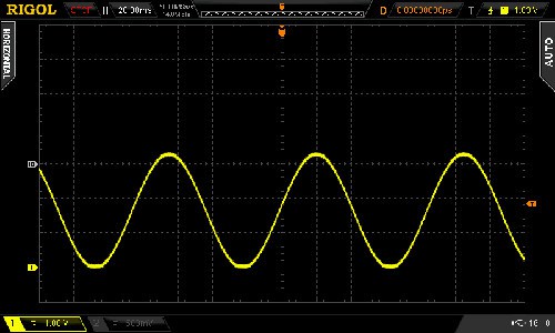
For the following DSO image dump, we changed the Vref to 3.3V – note the change in the maxima on the sine wave:
Now you can experiment with the DAC to make sound effects, signals or control other analogue circuits.

Using the ADCs (analogue-to-digital converters)

If you’ve used the analogRead() function on your Arduino (way back in Chapter One) then you’re already familiar with an ADC. With out PCF8591 we can read a voltage between zero and the Vref and it will return a value of between zero and 255 which is directly proportional to zero and the Vref. For example, measuring 3.3V should return 168. The resolution (8-bit) of the ADC is lower than the onboard Arduino (10-bit) however the PCF8591 can do something the Arduino’s ADC cannot. But we’ll get to that in a moment.

First, to simply read the values of each ADC pin we send a control byte to tell the PCF8591 which ADC we want to read. For ADCs zero to three the control byte is 0x00, 0x01, ox02 and 0x03 respectively. Then we ask for two bytes of data back from the ADC, and store the second byte for use. Why two bytes? The PCF8591 returns the previously measured value first – then the current byte. (See Figure 8 in the data sheet). Finally, if you’re not using all the ADC pins, connect the unused ones to GND.

The following example sketch simply retrieves values from each ADC pin one at a time, then displays them in the serial monitor:

// Example 52.3 PCF8591 ADC demo
// http://tronixstuff.com/tutorials Chapter 52
// John Boxall June 2013
#include "Wire.h"
#define PCF8591 (0x90 >> 1) // I2C bus address
#define ADC0 0x00 // control bytes for reading individual ADCs
#define ADC1 0x01
#define ADC2 0x02
#define ADC3 0x03
byte value0, value1, value2, value3;
void setup()
{
 Wire.begin();
 Serial.begin(9600);
}
void loop()
{
 Wire.beginTransmission(PCF8591); // wake up PCF8591
 Wire.write(ADC0); // control byte - read ADC0
 Wire.endTransmission(); // end tranmission
 Wire.requestFrom(PCF8591, 2);
 value0=Wire.read();
 value0=Wire.read();
 Wire.beginTransmission(PCF8591); // wake up PCF8591
 Wire.write(ADC1); // control byte - read ADC1
 Wire.endTransmission(); // end tranmission
 Wire.requestFrom(PCF8591, 2);
 value1=Wire.read();
 value1=Wire.read();
 Wire.beginTransmission(PCF8591); // wake up PCF8591
 Wire.write(ADC2); // control byte - read ADC2
 Wire.endTransmission(); // end tranmission
 Wire.requestFrom(PCF8591, 2);
 value2=Wire.read();
 value2=Wire.read();
 Wire.beginTransmission(PCF8591); // wake up PCF8591
 Wire.write(ADC3); // control byte - read ADC3
 Wire.endTransmission(); // end tranmission
 Wire.requestFrom(PCF8591, 2);
 value3=Wire.read();
 value3=Wire.read();
 Serial.print(value0); Serial.print(" ");
 Serial.print(value1); Serial.print(" ");
 Serial.print(value2); Serial.print(" ");
 Serial.print(value3); Serial.print(" ");
 Serial.println();
}

Upon running the sketch you’ll be presented with the values of each ADC in the serial monitor. Although it was a simple demonstration to show you how to individually read each ADC, it is a cumbersome method of getting more than one byte at a time from a particular ADC.

To do this, change the control byte to request auto-increment, which is done by setting bit 2 of the control byte to 1. So to start from ADC0 we use a new control byte of binary 00000100 or hexadecimal 0x04. Then request five bytes of data (once again we ignore the first byte) which will cause the PCF8591 to return all values in one chain of bytes. This process is demonstrated in the following sketch:

// Example 52.4 PCF8591 ADC demo
// http://tronixstuff.com/tutorials Chapter 52
// John Boxall June 2013
#include "Wire.h"
#define PCF8591 (0x90 >> 1) // I2C bus address
byte value0, value1, value2, value3;
void setup()
{
 Wire.begin();
 Serial.begin(9600);
}
void loop()
{
 Wire.beginTransmission(PCF8591); // wake up PCF8591
 Wire.write(0x04); // control byte - read ADC0 then auto-increment
 Wire.endTransmission(); // end tranmission
 Wire.requestFrom(PCF8591, 5);
 value0=Wire.read();
 value0=Wire.read();
 value1=Wire.read();
 value2=Wire.read();
 value3=Wire.read();
 Serial.print(value0); Serial.print(" ");
 Serial.print(value1); Serial.print(" ");
 Serial.print(value2); Serial.print(" ");
 Serial.print(value3); Serial.print(" ");
 Serial.println();
}

Previously we mentioned that the PCF8591 can do something that the Arduino’s ADC cannot, and this is offer a differential ADC. As opposed to the Arduino’s single-ended (i.e. it returns the difference between the positive signal voltage and GND, the differential ADC accepts two signals (that don’t necessarily have to be referenced to ground), and returns the difference between the two signals. This can be convenient for measuring small changes in voltages for load cells and so on.

Setting up the PCF8591 for differential ADC is a simple matter of changing the control byte. If you turn to page seven of the data sheet, then consider the different types of analogue input programming. Previously we used mode ’00’ for four inputs, however you can select the others which are clearly illustrated, for example:
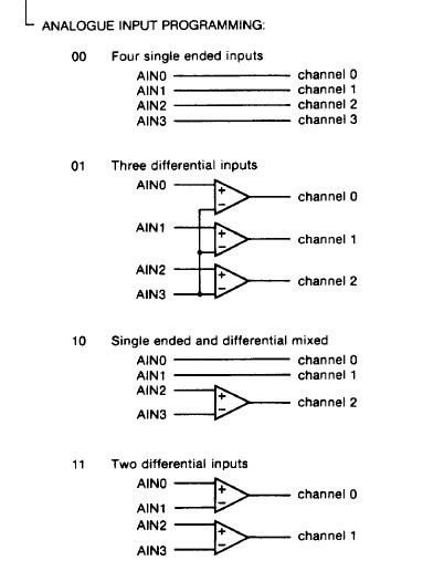
So to set the control byte for two differential inputs, use binary 00110000 or 0x30. Then it’s a simple matter of requesting the bytes of data and working with them. As you can see there’s also combination single/differential and a complex three-differential input. However we’ll leave them for the time being.

Conclusion

Hopefully you found this of interest, whether adding a DAC to your experiments or learning a bit more about ADCs. We’ll have some more analogue to digital articles coming up soon, so stay tuned. And if you enjoy my tutorials, or want to introduce someone else to the interesting world of Arduino – check out my new book “Arduino Workshop” from No Starch Press.

In the meanwhile have fun and keep checking into tronixstuff.com. Why not follow things on twitterGoogle+, subscribe  for email updates or RSS using the links on the right-hand column? And join our friendly Google Group – dedicated to the projects and related items on this website. Sign up – it’s free, helpful to each other –  and we can all learn something.

The post Tutorial – Arduino and PCF8591 ADC DAC IC appeared first on tronixstuff.
A custom Pi shield or an Arduino?

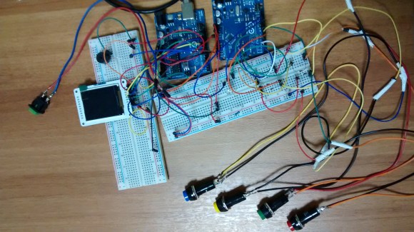
As more and more people get a Pi they are asking how to interface it to their robot. I do not own a Pi but I looked at the GPIO pins available for interfacing. Apart from general digital I/O pins you have I2C, SPI and Serial interfacing available. I assume there is a library or something that allows these pins to be easily access from within the Linux operating system.

So the question becomes do you just use another MCU such as an Arduino to provide the necessary I/O functionality or do you use a custom shield?

read more

Let's Make Robots 04 Oct 13:38
arduino  i2c  ideas  interface  pi  raspberry  serial  shield  spi  

DSS Circuits - bringing SMD to DIY

This is a cool site with some interesting PCB's including an I2C GPS Arduino sheild. The owner of the site, Wayne Truchsess has also written a great I2C library that I am using now.

Check out his open source tracking device that featured on Kickstarter here: http://www.kickstarter.com/projects/dsscircuits/open-source-tracking-device

read more

Let's Make Robots 18 Sep 06:52
arduino  gps  i2c  library  pcb  robot  shield  shops  smd