Posts with «i2c» label

New improved I2C library for Arduino

Recently I have been experimenting a lot with I2C. My A.I. project uses the DS1307 RTC and a work project uses several I2C ADC's.

Normally the Arduino Wire library works fine with the DS1307 RTC but it does not play well with 3.3V @ 8MHz devices such as my Micro Magician and does not support fast mode (400KHz). It also has some compatibility issues with some devices such as my ADC's because it does not support a repeated start condition.

read more

Let's Make Robots 16 Sep 04:22
8mhz  arduino  clock  cool guides  fast  i2c  library  mode  

Arduino, GPS and Display i2C…


En este nuevo tutorial Arduino by ARDUTEKA, estudiamos a fondo los módulos GPS, en concreto los módulos diseñados por LIBELIUM, para aprender a extraer y comprender todas las tramadas de datos que recibimos de los GPS y posteriormente, tratar esa información para mostrar en un display con bus i2C datos como la latitud, longitud, altura y hora UTC…


[Via: Arduteka]


Magnetometer was not fried

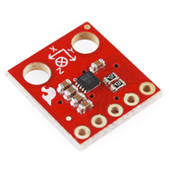
MAG3110 breakout board by Sparkfun

In Learning to Use I2C, I talked about the difficulty I’d been having getting the MAG3110 breakout board from Sparkfun to work, and my fears that I had burned it out by running it overnight at 5v (instead of the rated 3v).  I suspected that my problem was really a software problem, but debugging the software when I was afraid that the hardware was fried seemed like an exercise in futility.

I bought another of the breakout boards from Sparkfun (they’re only $15), and soldered on a header yesterday.  The code failed in almost exactly the same way with the new (presumed good) part as with the old (presumed fried) part, so I was convinced that the problem was indeed in the software.

I spent half of yesterday and most of this morning carefully rewriting the library of I2C interface code.  I was starting with example code from Sparkfun for the MMA8452Q accelerometer, which I had generalized to handle other I2C devices.

The library worked fine with the accelerometer, so I thought it was ok, but it did not work with the magnetometer. I added a lot of error checking (making sure that the microprocessor was in the expected state after each I2C operation), and found that things were not working as expected. The extra error checking made it much easier to diagnose the problems. I had to re-read the I2C documentation in the ATMega328 datasheet several times, to make sure that I had all the details right (I didn’t, of course). The documentation in that data sheet is better than several of the tutorials I’ve seen on line, and is both thorough and comprehensible in describing the interface.

I did not implement all features of the I2C  interface—in fact, I have a rather minimal implementation that uses polling rather than interrupts and assumes that the Arduino will always be the bus master.  Those assumptions are fine for most Arduino projects, which just use the I2C bus for talking to a handful of peripherals, but sometime in the future I may need to make a more complete set of code that can handle multiple masters, the Arduino as a slave device, and interrupts rather than polling and waiting for operations to finish.

Because I was more interested in simplicity and robustness than speed, I rewrote the code so that transactions were finished (and appropriate status checked) before functions returned.  With these changes I found that the STOP condition was not happening, despite being requested.  All other operations on the bus are checked with the TWINT bit  of the TWCR register and the upper bits of the TWSR register, but determining that STOP has completed requires checking the TSWTO bit of the TWCR register. The code I had started from just checked the TWINT bit for the other operations, and had a fixed timeout that was too short—it did no checking at all on the STOP state, just adding a fixed delay.

Once I got the STOP timing cleaned up (and earlier, making sure to send NAK when reading the last byte), everything worked fine.  The accelerometer code  had probably worked ok because there were enough delays after stops that the stops completed, even though I had not checked to make sure.  With the fixed code, even the magnetometer that I thought I had fried seems to work ok.

The interface for the students in the Robotics Club is fairly simple (much simpler than the standard “Wire” library):

// Read one register
uint8_t i2cReadRegister(uint8_t i2c_7bit_address, uint8_t address);
// Read num_to_read registers starting at address
void i2cReadRegisters(uint8_t i2c_7bit_address, uint8_t address, uint8_t num_to_read, uint8_t * dest);

// Write one register
void i2cWriteRegister(uint8_t i2c_7bit_address, uint8_t address, uint8_t data);
// Write num_to_write registers, starting at address
void i2cWriteRegisters(uint8_t i2c_7bit_address, uint8_t address, uint8_t num_to_write, const uint8_t *data);

I suppose I should check that there are no problems when I connect both devices to the same I2C bus, before handing this over to the students to use for their robot.

I should also put the i2c.h and i2c.cpp in some public place for others to use (perhaps on github? maybe on my web pages at work?). It is really a shame that WordPress.com does not permit code-like files as pages.

Related articles

Tagged: accelerometer, Arduino, i2c, magnetometer, robotics, SparkFun, SparkFun Electronics

I2SDv3 - Arduino buckler with microSD

The Wyolum machine (these are the people who generously offered $3000 in innovation grants, with no strings attached) is forging ahead with a new and improved version of I2SD.
I just received their v3 prototype and it looks impressive. I must say it is the most feature-rich data logger / SD card backpack (here is the list of the competing products that I compared with).

Like its predecessor, I2SD v3 is a software-compatible Arduino (ATmega328/16MHz) with extras. It has on-board microSD card, DS3231 extremely accurate real-time-clock with backup battery, infrared receiver and 2 LED indicators for errors or status.


I2SDv3 comes assembled (all SMD), with the bootloader burnt in. Sketches can be uploaded through the FTDI connector.

The board can be plugged directly into Arduino, using one row of headers (A0-A4-GND-RST), hence the name "buckler" (like a "semi-shield", got it?)
I2SDv3 also offers header access to D4-D7 (v2 lacked that; my complaint was heard :), and it is compatible with the ChronoDot headers.

To test it, I decided to try the OpenLog library, by Nathan Seidle of Sparkfun. Surprisingly, it worked without a glitch from the first try. Well, kind of, I had to read the documentation :), and to change HardwareSerial.cpp, a "system file" (function SIGNAL(USART_RX_vect) is redefined in OpenLog.pde).

To emulate the OpenLog board closer, I changed the code to use D2 for the status LED, as shown:

from
#define STAT1  5 //On PORTD
int statled1 = 5;  //This is the normal status LED

to
#define STAT1  2 //On PORTD
int statled1 = 2;  // status LED on I2SDv3;

Note: The second LED of OpenLog board is connected to SCK (D13), so it blinks when the SD card is active (while reading or writing). The second LED on I2SDv3, being on D3, cannot be easily re-purposed.

Following OpenLog documentation, I connected to I2SDv3 using CoolTerm, typed in some text, pressed CtrlZ three times and voila!: file LOG0001.TXT got created and it contained the characters I typed in. Cool indeed.

Note: OpenLog won't compile with Arduino 1.0 IDE without some minor changes, as follows:
1. "WProgram.h" replaced everywhere with "Arduino.h"
2. function SdFile::write(uint8_t) must return size_t now (since it is virtual function defined in Stream.h); both SdFile.cpp and SdFat.h will need to be updated to reflect that.

Reminder: The OpenLog library should work with FAT32-formatted SD cards as well as FAT16. I will test it as soon as I get a 4GB microSD card.


Wise time with Arduino 21 Jan 00:25
i2c  sd card  

I2SDv3 - Arduino buckler with microSD

The Wyolum machine (these are the people who generously offered $3000 in innovation grants, with no strings attached) is forging ahead with a new and improved version of I2SD.
I just received their v3 prototype and it looks impressive. I must say it is the most feature-rich data logger / SD card backpack (here is the list of the competing products that I compared with).

Like its predecessor, I2SD v3 is a software-compatible Arduino (ATmega328/16MHz) with extras. It has on-board microSD card, DS3231 extremely accurate real-time-clock with backup battery, infrared receiver and 2 LED indicators for errors or status.


I2SDv3 comes assembled (all SMD), with the bootloader burnt in. Sketches can be uploaded through the FTDI connector.

The board can be plugged directly into Arduino, using one row of headers (A0-A4-GND-RST), hence the name "buckler" (like a "semi-shield", got it?)
I2SDv3 also offers header access to D4-D7 (v2 lacked that; my complaint was heard :), and it is compatible with the ChronoDot headers.

To test it, I decided to try the OpenLog library, by Nathan Seidle of Sparkfun. Surprisingly, it worked without a glitch from the first try. Well, kind of, I had to read the documentation :), and to change HardwareSerial.cpp, a "system file" (function SIGNAL(USART_RX_vect) is redefined in OpenLog.pde).

To emulate the OpenLog board closer, I changed the code to use D2 for the status LED, as shown:

from
#define STAT1  5 //On PORTD
int statled1 = 5;  //This is the normal status LED

to
#define STAT1  2 //On PORTD
int statled1 = 2;  // status LED on I2SDv3;

Note: The second LED of OpenLog board is connected to SCK (D13), so it blinks when the SD card is active (while reading or writing). The second LED on I2SDv3, being on D3, cannot be easily re-purposed.

Following OpenLog documentation, I connected to I2SDv3 using CoolTerm, typed in some text, pressed CtrlZ three times and voila!: file LOG0001.TXT got created and it contained the characters I typed in. Cool indeed.

Note: OpenLog won't compile with Arduino 1.0 IDE without some minor changes, as follows:
1. "WProgram.h" replaced everywhere with "Arduino.h"
2. function SdFile::write(uint8_t) must return size_t now (since it is virtual function defined in Stream.h); both SdFile.cpp and SdFat.h will need to be updated to reflect that.

Reminder: The OpenLog library should work with FAT32-formatted SD cards as well as FAT16. I will test it as soon as I get a 4GB microSD card.

Wise time with Arduino 21 Jan 00:25
i2c  sd card  

3-Digit 7-Segment Display With an SAA1064


Working on the grinder timer project, I built out a basic circuit (EAGLE .sch) with an NXP SAA1064 and resurrected a test sketch (Arduino .pde) for it. The SAA1064 works beautifully for driving common anode 4-digit 7-segment displays with constant current per segment, from 3 to 21 mA in 3mA increments; in this case I'm only driving three digits since that's what the design calls for.

There are two buttons in the test sketch (on D10 and D11), the first to change count modes (seconds, tenths, hundredths, hex, and "chase") and the second to cycle through the seven current settings.

This schematic is identical to one I did a board layout for with an SO24 package chip, but for some reason those boards didn't work; maybe something in manufacture or assembly bridged pins somewhere. I'll redo the layout and see what happens, with vias further from pads.