Posts with «grinder timer» label

New Workshop!

We moved recently, and one of the features that drew us to our new home was a sun room in the back, maybe 8'x15', full of light and perfect for a workshop!

One corner is ideal for the laser, with a dryer vent for routing its (filtered) fumes outside. With two rolling racks for storage and two desks, I hope we'll have room for a small heavy bench and drill press. Good thing the Printrbot is (er, will be) small, we have big plans for this little room.

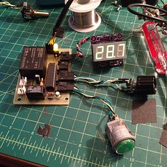
I got a kick out of reading my "Workshop!" post from two years ago, most of those projects haven't moved too much forward, but the grinder timer has gone through a few versions and the flight suit ended up being by far my most complicated project so far.

Flight Suit Excursions, Grinder Timer V4

I've had a lot of fun with my Arduino-based projects lately! I got the flight suit working again for Decompression last month and had a blast dancing and hanging out in the crushing crowds. I wore it again last Saturday night for the work Halloween party and then again Monday night for 7 Walkers at the Great American Music Hall where Liz balanced out my high tech audio meter with her low tech VU meter-- analog and fully manual :)

Next up is V4 of the coffee grinder timer, a one-off to replace the V2 timer we're using now. It's an all-in-one circuit board designed to fit in a Hammond 1455-series case. There's an AC-DC converter on the board to supply 5V, and breakouts on the left (in white) for power and on the right (black) for the display, light sensor, rotary encoder, and lit button. I may finish it without the light sensor since it's so close to being done and looks so much better (especially on the inside!) than what we're running now.

3-Digit 7-Segment Display With an SAA1064


Working on the grinder timer project, I built out a basic circuit (EAGLE .sch) with an NXP SAA1064 and resurrected a test sketch (Arduino .pde) for it. The SAA1064 works beautifully for driving common anode 4-digit 7-segment displays with constant current per segment, from 3 to 21 mA in 3mA increments; in this case I'm only driving three digits since that's what the design calls for.

There are two buttons in the test sketch (on D10 and D11), the first to change count modes (seconds, tenths, hundredths, hex, and "chase") and the second to cycle through the seven current settings.

This schematic is identical to one I did a board layout for with an SO24 package chip, but for some reason those boards didn't work; maybe something in manufacture or assembly bridged pins somewhere. I'll redo the layout and see what happens, with vias further from pads.