Posts with «hardware» label

The Dar es Salaam Hacker Scene and Gamut Detection

We’re on a sort of vacation in Tanzania at the moment and staying in a modest hotel away from the tourist and government district. It’s a district of small shops selling the same things and guys repairing washing machines out on the sidewalk. The guys repairing washing machines are more than happy to talk. Everybody’s amazingly friendly here, the hotel guy grilled us for an hour about our home state. But I really didn’t expect to end up in a conversation about computer vision.

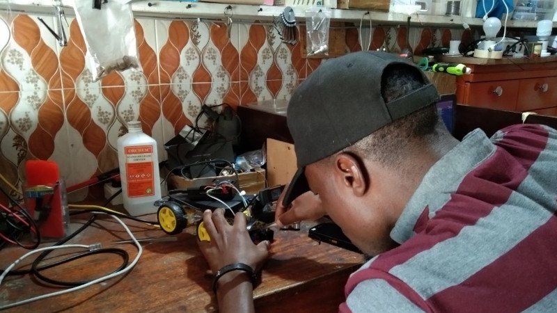
In search of some yogurt and maybe something cooler to wear, we went on a little walk away from the hotel. With incredible luck we found a robotics shop a few blocks away. Mecktonix is a shop about two meters each way, stuffed full of Arduinos, robots, electronics components, servos, and random computer gear, overseen by [Yohanna “Joe” Harembo]. Nearby is another space with a laser engraver and 3D printer. The tiny space doesn’t stop them from being busy. A constant stream of automotive tech students from the nearby National Institute of Transport shuffle in for advice and parts for class assigned projects.

In between students, Joe demos an autonomous car he’s working on. In classic hacker fashion, he first has to reattach the motor driver board and various sensors, but then he demos the car and its problem –  the video frame rate is very slow. We dive in with him and try to get some profiling using time.monotonic_ns(). He’s never done profiling before, so this is a big eye opener. He’s only processing one video frame every 4.3 seconds, using YOLO on a Pi 3, and yup, that’s the problem.  I suggest he change to gamut detection or a Pi 4.

Gamut Detection

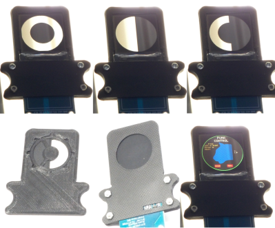
If you’re not familiar with gamut detection, it’s one of the simplest of all computer vision techniques, so it’s easy to implement on slow processors and almost trivial to code. Basically, it’s “look for a color”.  If you want your robot to follow you, wear a lime green T shirt. Now the robot just has to look for lime green. Same for catching a ball or following a line. The algorithm is simple – convert each pixel to HSV, where hue corresponds to the direction around the color wheel,  saturation corresponds to how concentrated the color is, and value how bright. Brightness depends on the lighting, so you can throw value away and just set limits for H and S. Anything within those limits is part of our target. The box formed by those limits is our “gamut”.

There are a couple speedups you can apply as well. First, ask yourself how much resolution you need from the camera. If you only want to track a green T shirt that’s never less than 24 pixels on screen, turn the resolution down by a factor of six each way and look for four-pixel T shirts. You now have 1/36th as much data to process and your algorithm runs 36 times faster. If you can’t control the camera resolution, you can shrink the image or just sample every nth pixel. Second, you can often ask for a YUV or YIQ image from the camera. Discard Y and set your limits in IQ or UV coordinates. It’s about the same as HSV.

Joe’s eating this up – he’s had limited chances to talk with somebody else who is into computer vision. As we write this, he’s still trying with YOLO, but at lower resolution. If it doesn’t work he’ll try gamut detection. And it’s not his only project. Passenger carrying motorcycles called pikipikis are common here. A student has a project to enforce passengers wearing a helmet, and we fiddle with the student’s project.

The Dar es Salaam Scene

There’s other tech happening in Tanzania too. A few blocks away is [Ruta Electronics], a similar sugar cube sized shop developing smart meters. Everything from cases to PCB etching happens in the tiny shop. Downtown there are a few tech startups. There’s a fab lab, mostly oriented towards children. And on a quiet side street off the main drag, there’s a tiny shop with three guys who are hacking like crazy.

For us, we’ve had a chance to make a friend from a different culture and play with a robot car together — what could be better?  When you’re traveling, are you on the lookout for other hackers or hackerspaces? It’s worth the effort and brings our community together in a way that even the internet can’t.

The Great Resistor Embiggens the Smallest Value

With surface-mount components quickly becoming the norm, even for homebrew hardware, the resistor color-code can sometimes feel a bit old-hat. However, anybody who has ever tried to identify a random through-hole resistor from a pile of assorted values will know that it’s still a handy skill to have up your sleeve. With this in mind, [j] decided to super-size the color-code with “The Great Resistor”.

How the resistor color-code bands work

At the heart of the project is an Arduino Nano clone and a potential divider that measures the resistance of the test resistor against a known fixed value. Using the 16-bit ADC, the range of measurable values is theoretically 0 Ω to 15 MΩ, but there are some remaining issues with electrical noise that currently limit the practical range to between 100 Ω and 2 MΩ.

[j] is measuring the supply voltage to help counteract the noise, but intends to move to an oversampling/averaging method to improve the results in the next iteration.

The measured value is shown on the OLED display at the front, and in resistor color-code on an enormous symbolic resistor lit by WS2812 RGB LEDs behind.

Inside The Great Resistor, the LEDs and baffle plates make the magic work

Precision aside, the project looks very impressive and we like the way the giant resistor has been constructed. It would look great at a science show or a demonstration. We’re sure that the noise issues can be ironed out, and we’d encourage any readers with experience in this area to offer [j] some tips in the comments below. There’s a video after the break of The Great Resistor being put through its paces!

If you want to know more about the history of the resistor color code bands, then we have you covered.  Alternatively, how about reading the color code directly with computer vision?

Plumbing Valves as Heavy Duty Analog Inputs

Input devices that can handle rough and tumble environments aren’t nearly as varied as their more fragile siblings. [Alastair Aitchison] has devised a brilliant way of detecting inputs from plumbing valves that opens up another option. (YouTube) [via Arduino Blog]

While [Aitchison] could’ve run the plumbing valves with water inside and detected flow, he decided the more elegant solution would be to use photosensors and an LED to simplify the system. This avoids the added cost of a pump and flow sensors as well as the questionable proposition of mixing electronics and water. By analyzing the change in light intensity as the valve closes or opens, you can take input for a range of values or set a threshold for an on/off condition.

[Aitchison] designed these for an escape room, but we can see them being great for museums, amusement parks, or even for (train) simulators. He says one of the main reasons he picked plumbing valves was for their aesthetics. Industrial switches and arcade buttons have their place, but certainly aren’t the best fit in some situations, especially if you’re going for a period feel. Plus, since the sensor itself doesn’t have any moving parts, these analog inputs will be easy to repair should anything happen to the valve itself.

If you’re looking for more unusual inputs, check out the winners of our Odd Inputs and Peculiar Peripherals contest or this typewriter that runs Linux.

Arduino Drum Platform Is Fast

Drums are an exciting instrument to learn to play, but often prohibitive if there are housemates or close neighbors involved. For that problem there are still electronic drums which can be played much more quietly, but then the problem becomes one of price. To solve at least part of that one, [Jeremy] turned to using an Arduino to build a drum module on his own, but he still had to solve yet a third problem: how to make the Arduino fast enough for the drums to sound natural.

Playing music in real life requires precise timing, so the choice of C++ as a language poses some problems as it’s not typically as fast as lower-level languages. It is much easier to work with though, and [Jeremy] explains this in great detail over a series of blog posts detailing his drum kit’s design. Some of the solutions to the software timing are made up for with the hardware on the specific Arduino he chose to use, including an even system, a speedy EEPROM, hardware timers, and an ADC that can sample at 150k samples per second.

With that being said, the hardware isn’t the only thing standing out on this build. [Jeremy] has released the source code on his GitHub page for those curious about the build, and is planning on releasing several more blog posts about the drum kit build in the near future as well. This isn’t the only path to electronic drums, though, as we’ve seen with this build which converts an analog drumset into a digital one.

Hack a Day 29 Jun 06:00

Highly Configurable Open Source Microscope Cooked Up In FreeCAD

What do you get when you cross a day job as a Medical Histopathologist with an interest in 3D printing and programming? You get a fully-baked Open Source microscope, specifically the Portable Upgradeable Modular Affordable (or PUMA), that’s what. And this is no toy microscope. By combining a sprinkle of off-the-shelf electronics available from pretty much anywhere, a pound or two of filament, and a dash of high quality optical parts, PUMA cooks up quite possibly one of the best open source microscopy experiences we’ve ever tasted.

GitHub user [TadPath] works as a medical pathologist and clearly knows a thing or two about what makes a great instrument, so it is a genuine joy for us to see this tasty project laid out in such a complete fashion. Many a time we’ve looked into an high-profile project, only to find a pile of STL files and some hard to source special parts. But not here. This is deliberately designed to be buildable by practically anyone with access to a 3D printer and an eBay account.

The project is not currently certified for medical diagnostics use, but that is likely only a matter of money and time. The value for education and research (especially in developing nations) cannot really be overstated.

A small selection of the fixed and active aperture choices

The modularity allows a wide range of configurations from simple ambient light illumination, with a single objective, great for using out in the field without electricity, right up to a trinocular setup with TFT-based spatial light modulator enabling advanced methods such as Schlieren phase contrast (which allows visualisation of fluid flow inside a live cell, for example) and a heads-up display for making measurements from the sample. Add into the mix that PUMA is specifically designed to be quickly and easily broken down in the field, that helps busy researchers on the go, out in the sticks.

The GitHub repo has all the details you could need to build your own configuration and appropriate add-ons, everything from CAD files (FreeCAD source, so you can remix it to your heart’s content) and a detailed Bill-of-Materials for sourcing parts.

We covered fluorescence microscopy before, as well as many many other microscope related stories over the years, because quite simply, microscopes are a very important topic. Heck, this humble scribe has a binocular and a trinocular microscope on the bench next to him, and doesn’t even consider that unusual. If you’re hungry for an easily hackable, extendable and cost-effective scope, then this may be just the dish you were looking for.

Thanks to [linus] for the delicious tip!

Arduino Powered Heat Pump Controller Helps Warm Your Toes

Heat pump heating technology is starting to pop up more and more lately, as the technology becomes cheaper and public awareness and acceptance improves. Touted as a greener residential heating system, they are rapidly gaining popularity, at least in part due to various government green policies and tax breaks.

[Gonzho] has been busy the last few years working on his own Arduino Powered Open Source heat pump controller, and the project logs show some nice details of what it takes to start experimenting with heat pumps in general, if that’s your game. Or you could use this to give an old system a new lease of life with an Arduino brain transplant.

In essence they are very simple devices; some kind of refrigerant is passed through a source of heat, absorbing some of it, it then flows elsewhere, and is compressed, which increases its temperature, before that increased heat is lost where the increase in temperature is desired.

This heat source could be a river, a mass of pipes buried in the ground, or simply the air around you. The source and quality of the heat source as well as the desired system operating temperature dictate the overall efficiency, and with ground-source systems it’s even possible to dump excess heat directly into the ground and store it for when required later. This could be the result of a residential cooling system, or even directly sourced from a solar heated setup.

This heat pumping process is reversible, so it is possible to swap the hot and cold ends, just by flipping some valves, and turn your space heater into a space cooler. This whole process can trace its roots back to the super talented Scottish professor, William Cullen who in 1748 was the first person on record to demonstrate artificial refrigeration.

The power needed to run the compressor pump and control gear is usually electrically derived, at least in non-vehicular applications, but the total power required is significantly less than the effective heating (or cooling) power that results.

We’ve covered a few heat pump hacks before, like this guy who’s been heating his house geothermally for years, but not so many platforms designed for experimentation from the ground up.

The associated GitHub project provides the gerber files as well as the Arduino code, so you’ve got a great starting point for your own heat pumping builds.

Hack a Day 08 Sep 21:00

Get Your Flex On With The FlowIO Platform

Hackaday Prize 2021 entry FlowIO Platform promises to be to pneumatics what Arduino is to Electronics. The modular platform comprises a common controller/valve block, a selection of differently sized pumps, and a few optional connectivity and sensing blocks. With Arduino software support as well as as Javascript and web-GUI, there’s a way to program this no matter what the level of experience the user has.

flowIO exploded view from http://www.softrobotics.io/flowio

This last point is a critical one for the mission [Ali Shtarbanov] from the MIT Media Lab is setting out for this project. He reminds us that in decades gone by, there was a significant barrier to entry for anyone building electronics prototypes. Information about how to get started was also much harder to by before the internet really got into gear.

It’s a similar story for software, with tools like Scratch and Python lowering the barrier to entry and allowing more people to get their toes wet and build some confidence.

But despite some earlier work by projects like the Soft Robotics Toolkit and Programmable-Air, making a start on lowering the bar for pneumatics support for soft robotics, and related applications, the project author still finds areas for further improvement. FlowIO was designed from the ground-up to be wearable. It appears to be much smaller, more portable and supports more air ports and a greater array of sensing and connectivity than previous Open Source work to date.

Creative Commons Hardware

Whilst you can take all the plans (free account signup required) and build yourself a FlowIO rig of your very own, the project author offers another solution. Following on from the Wikipedia model of free sharing and distribution of information, FlowIO offers its hardware for free, for the common good. Supported by donations to the project, more hardware is produced and distributed to those who need it. The only ask is that redundant kits are passed on or returned to base for upgrade, rather than landfill.

The HackadayPrize2021 is Sponsored by:

From Printer to Vinyl Cutter

Some might look at a cheap inkjet printer and see a clunky device that costs more to replace the ink than to buy a new one. [Abhishek Verma] saw an old inkjet printer and instead saw a smooth gantry and feed mechanism, the perfect platform to build his own DIY vinyl cutter.

The printer was carefully disassembled. The feed mechanism was reworked to be driven by a stepper motor with some 3D printed adapter plates. A solenoid-based push/pull mechanism for the cutting blade was added with a 3D printed housing along with a relay module. An Arduino Uno takes in commands from a computer with the help of a CNC GRBL shield.

What we love about this build is the ingenuity and reuse of parts inside the old printer. For example, the old PCB was cut and connectors were re-used. From the outside, it’s hard to believe that HP didn’t manufacture this as a vinyl cutter.

If you don’t have a printer on hand, you can always use your CNC as a vinyl cutter. But if you don’t have a CNC, [Abhishek] shares all the STL files for his cutter as well as the schematic. Video after the break.

Making Minty Fresh Music With Markov Chains: The After Eight Step Sequencer

Step sequencers are fantastic instruments, but they can be a little, well, repetitive. At it’s core, the step sequencer is a pretty simple device: it loops through a series of notes or phrases that are, well, sequentially ordered into steps. The operator can change the steps while the sequencer is looping, but it generally has a repetitive feel, as the musician isn’t likely to erase all of the steps and enter in an entirely new set between phrases.

Enter our old friend machine learning. If we introduce a certain variability on each step of the loop, the instrument can help the musician out a bit here, making the final product a bit more interesting. Such an instrument is exactly what [Charis Cat] set out to make when she created the After Eight Step Sequencer.

The After Eight is an eight-step sequencer that allows the artist to set each note with a series of potentiometers (which are, of course, housed in an After Eight mint tin). The potentiometers are read by an Arduino, which passes MIDI information to a computer running the popular music-oriented visual programming language Max MSP. The software uses a series of Markov Chains to augment the musician’s inputted series of notes, effectively working with the artist to create music. The result is a fantastic piece of music that’s different every time it’s performed. Make sure to check out the video at the end for a fantastic overview of the project (and to hear the After Eight in action, of course)!

[Charis Cat]’s wonderful creation reminds us of some the work [Sara Adkins] has done, blending human performance with complex algorithms. It’s exactly the kind of thing we love to see at Hackaday- the fusion of a musician’s artistic intent with the stochastic unpredictability of a machine learning system to produce something unique.

Thanks to [Chris] for the tip!

Arduino Wannabe Should Have Used a 555. Oh Wait, It Does.

It’s a little known secret that when the Hackaday writers gather in their secret underground bunker to work on our plans for world domination, we often take breaks to play our version of the corporate “Buzzword Bingo”, where paradigms are leveraged and meetings circle back to loop in offline stakeholders, or something like that. Our version, however, is “Comment Line Bingo”, and right in the middle of the card is the seemingly most common comment of all: “You should have used a 555,” or variations thereof.

So it was with vicious glee that we came across the Trollduino V1.0 by the deliciously named [Mild Lee Interested]. It’s the hardware answer to the common complaint, which we’ll grant is often justified. The beautiful part of this is that Trollduino occupies the same footprint as an Arduino Uno and is even pin-compatible with the microcontroller board, or at least sort of. The familiar line of components and connectors sprout from the left edge of the board, and headers for shields line the top and bottom edges too. “Sketches” are implemented in hardware, with jumpers and resistors and capacitors of various values plugged in to achieve all the marvelous configurations the indispensable timer chip can be used for. And extra points for the deliberately provocative use of Comic Sans in the silkscreen.

Hats off to [Lee] for a thoroughly satisfying troll, and a nice look at what the 555 chip can really do. If you want a more serious look at the 555, check out this 555 modeled on a breadboard, or dive into the story of the chip’s development.

Hack a Day 17 Jan 09:00