Posts with «diy» label

Arduino Uno Controlling a Lego Mindstorms Elevator

NooTrix submitted us a 4-part tutorial to build a Lego Mindstorm Elevator controlled by an Arduino Uno:

 The elevator is built using components from an old Lego Mindstorms RCX 1.5. For the control part, we use an Arduino Uno board instead of the obsolete Lego RCX brick. The motor and sensors are from Lego. The connection to motor is done using a set of transistors organized in a H-Bridge.

The goal of the project is to show how to control Lego parts (motor, sensors, …) using an Arduino:

the elevator carries a smartphone and keep it level which is useful for taking snapshots of documents instead of scanning them. Full description, a step by step tutorial, as well as pictures, videos are available online.

All circuit schematics and source code are released under a free open source license (creative commons).

Arduino Blog 03 Apr 16:39
arduino  diy  elevator  lego  mindstorm  

This Arduino-powered business card looks like a Game Boy and runs Tetris (video)

Off-white business cards with Silian Rail lettering are so passé -- these days; it's all about creativity. This Game Boy look-alike, for instance, demonstrates its creator's skills in one fell swoop: It doesn't just display a résumé, it's also a simple gaming handheld that can play Tetris. The device was made by Oregon programmer Kevin Bates, who calls it the Arduboy, because it uses a barebones Arduino board (the tiny computer also found inside Kegbot and Fish on Wheels) connected to an OLED screen. To make the hand-held gaming experience as authentic as possible, he also equipped the card with capacitive touch buttons, a speaker and a replaceable battery that lasts up to nine hours.

Comments

Via: Boing Boing

Source: Bateske

Touch Board kit combines an Arduino heart with touch sensors, conductive paint

Capacitive sensing isn't limited to your smartphone. In fact, you can use contact with human skin (or any other conductive surface) to trigger almost any circuit. And the Touch Board from Bare Conductive wants you to combine your DIY spirit with the ability to turn practically any surface into a sensor. At the heart is an Arduino compatible microcontroller (based on the Leonardo) with a few extras baked in, including a Freescale touch sensor connected to 12 electrodes and an audio processor for triggering MIDI sounds or MP3 files. While you can simply trigger the electrodes by touching them or connecting them to any conductive material, such as a wire, the Electric Paint Pen really opens up the input possibilities. It's just like a paint marker, often used for small scale graffiti, except it spits out conductive black ink that can turn a wall, a piece of paper or almost anything else into a trigger. In fact, it's preloaded with a bunch of sample sounds on a microSD card so that you can simply paint a soundboard out of the box.

The Kickstarter startup has already more than quadrupled its target funding, but there's still a few days left to get in on the fun. For £45 you can get a Touch Board (with microSD card), an Electric Paint Pen and your choice of either a micro USB cable or a rechargable lithium battery for your untethered projects. And, since its pin compatible with most Arduino shields, you can add even more capabilities to the Touch Board for more complex projects. For example, pop on a relay switch shield, like the one included in the £100 light switch kit, and you can turn your lights on and off or tackle any other high-voltage project on your wishlist. And, since the Electric Paint can also act as a proximity sensor, you could potentially build a dimmer that brightens the room as you bring your hand closer to the wall. For the requisite sales pitch and demo, check out the video after the break.

Filed under: Misc

Comments

Source: Touch Board (Kickstarter)

EMW kick-starts JuiceBox, a $99 Level 2 DIY charging station

Electric vehicle charging stations aren't cheap: one of the most affordable Level 2 (240V) units sells for $450 and only supplies 16A. Electric Motor Works (EMW) -- which is best known for its electric conversion kits -- wants to change this with JuiceBox, a 15kW Level 2 EV charger that costs just $99 in kit form (plus $10 shipping). The device, which is launching on Kickstarter today, supplies up to 62A and operates on both 120V and 240V. It's built around an Arduino microcontroller and EMW is making both the hardware and software open source.

But wait, there's more! The company is also crowdfunding a Premium Edition of JuiceBox ($199 in kit form) which adds time-of-day charging, a color LCD, ground-fault plus output protection (for outdoor use) and a unique enclosure (hopefully as funky as the one in the picture above). While the DIY kits only require basic assembly and soldering skills, you'll be able to buy fully assembled versions for $100 more. At $329 (shipped), a ready-to-use JuiceBox Premium Edition undercuts other similar charging stations by several hundred dollars. The catch? You'll have to supply your own cables (or buy them separately from EMW), including one with a standard J1772 EV connector. Hit the source link below to check out the campaign, and take a look at the PR after the break.

Filed under: Transportation

Comments

Source: EMW (Kickstarter)

Sound Makers Unite at Stanford

This weekend I went down to Palo Alto to check out the DIY Musical Instrument Tailgate Party, hosted by Thingamajigs and the Center for Computer Research in Music and Acoustics (CCRMA).

Read the full article on MAKE

TRUE ANALOG AUDIO VOLUME CONTROL (T.A.A.V.C.).


More:   Video1   and   Video2

Now my Arduino can precisely measure audio input (VU meter),   and obviously, next thing that comes to mind right after measurements, is regulation or control. There are many different ways how to electronically adjust audio volume or level of AC signal.  I’ll name a few:

  • Specifically design IC, Digital potentiometers.
  • Mechanical potentiometers, driven by servo / motors.
  • Vacuum tubes amplifiers in “variable-mu” configuration.
  • Resistive opto-isolators.

First category (#1) fits nicely for arduino project. But it’s not interesting to me. My apologies to someone, who was searching an example of interface between arduino and digital pot. Other people don’t tolerate semiconductors in audio path ( tube sound lovers ). Third option would make them happy, only (#3) requires high voltage and difficult to accomplish on low hobbyist budget, so I left it out of the scope. Mechanical pot (#2) would be good solution to satisfy Hi-Fi perfectionists and arduino fans. The same time response time of mechanical parts is too slow, verdict – discarded.  (#4) have been in use since 1960s, but would you like your lovely music to be adjusted by highly toxic CdSe / CdS ?  I don’t think so. Wiki says opto-isolators have low THD distortion level, less than 0.1%. Probably true, but apart from technical aspect, there is always psychological, poisonous CdSe affects my perception.

How about variable resistor in it’s simplest form – tungsten wire? Where you can get one? In the electrical bulb. Perfect material for audiophiles – where distortion could get into ? – It’s pure metal ! And here is my design of the “basic cell” – True Analog Audio Volume Control (T.A.A.V.C.)

As you can see, cell consists of 5 bulbs plus 1 resistor. All elements form 2 attenuation stages, basically – voltage dividers with variable resistors. Resistive values of bulbs proportional to temperature, which is easy to control passing DC current through. To make it work with the biggest possible dynamic range, middle bulb is also heated up by current flow from two differential control lines / phases.

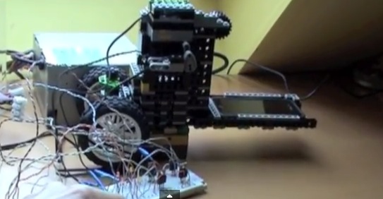
 Hardware prototype / Proof of Concept.

Differential Power Amplifier (PA) IC LM4863  is used as DC current source for control lines. Circuitry powered from 5V regulated switching power supply (4A).  Bulbs – clear mini lights, 2.5V, approximately 200 mA. Cold state resistance about 1.2 – 1.5 Ohm, hot state resistance is rising up to 15 Ohm.  Volume regulator could be connected to any audio source with output impedance no more than 32 Ohm, for example, headphones output. For test I used second channel of the PA, that shown in “optional” box on the left side. Second channel is a “nice to have” feature  in stereo version of the project, when both channels would drive two separate TAAVC cells, so using it as a “buffer” amplifier may be not an option.

Results.

  Measured attenuation  range of the “basic cell” is  20 dB, or 10 x times.

 to be continue…

 Chart, PWM (Voltage) to Attenuation:

 Quite interesting, isn’t it? I was not expecting it’s to be linear, but changing direction surprised me. There is one things, which could explain such abnormality, is that when voltage on the control lines 1 and 2 ( LM4863 outputs ) is approaching power rails, output impedance of the power amplifier is increasing, and consequently, attenuation characteristics of the basic cell deteriorate. It means, that in order to keep attenuation curve gradually declining, more powerful PA necessary. For now, I limited PWM to 0 – 200 range.

I’m thinking, STA540  powered from +12V, and 5 V bulbs would make sense to try next time.  Probably, replacing middle bulb for less current hungry, will increase max attenuation per cell up to 30-35 dB.

 O’K, after I get this data, how could I “straighten it up” for practical use ?  Volume control device, could be linear or logarithmic, but chart doesn’t resemble nether of this. And this is exactly what I need Arduino for.

Linearization.

 If you, by chance, have read this page, than you know how to do this part. Polynomial approximation. Unfortunately,  2-nd degree polynomial I used last time is not enough for VERY non-linear curve like I have. So, I “upgraded” my calibration subroutine (method: LEAST SQUARES) up to 3-rd degree:

void calibrate()
{
 //Least squares 3-rd degree polynomial coefficient calculation
 float arr[10][5] ={{0},{0}}, err[10] = {0}, coeff[10] = {0};

 err[0] = 10;
 for(uint8_t i = 1; i < 7; i++)
 {
  err[i] = 0;
  for(uint8_t j = 0; j < 10; j++)
  {
   err[i] += pow(level_table[j], i);
  }
 }

 for(uint8_t i = 0; i < 4; i++)
 {
  for(uint8_t j = 0; j < 4; j++)
  {
   arr[i][j] = err[i+j];
  }
 }

 for(uint8_t i = 0; i < 4; i++)
 {
  arr[i][4] = 0;
  for(uint8_t j = 0; j < 10; j++)
  {
   if (i==0) arr[i][4] += calibration[j];
   else arr[i][4] += calibration[j] * pow(level_table[j], i);
  }
 }

 for(uint8_t k = 0; k < 4; k++)
 {
  for(uint8_t i = 0; i < 4; i++)
  {
   if ( i != k )
   {
    for(uint8_t j = (k + 1); j < 5; j++)
    {
     arr[i][j] -= ((arr[i][k] * arr[k][j]) / arr[k][k]);
    }
   }
  }
 }

 union split_float {
 uint16_t tegri[2];
 float loatf;
 } sf; 

 for(uint8_t i = 0; i < 4; i++)
 {
  coeff[i] = ( arr[i][4] / arr[i][i]);
  sf.loatf = coeff[i];
  store_entry(( 2 * i ), sf.tegri[0] );
  store_entry(( 1 + (2 * i)), sf.tegri[1] );
 }
}

Procedure takes 10 data samples as input, calculates 4 coefficients and stores them in EEPROM memory.

VU meter based on Arduino UNO ( in minimum configuration Arduino and DC offsetting circuit ) should be connected right to T.A.A.V.C. output. Everything works in automatic mode, with results printed on serial monitor for review. Stable AC input is necessary, which easy to get from any PC sound card based signal generator, recorded media file or lab sine-wave generator. Arduino also provides PWM for T.A.A.V.C       via pin D3 (TIMER2 OCR2B).

Link to download Arduino UNO sketch: T.A.A.V.C.

to be continue…audio compressor, .

Last part,

Dynamic Range Compressor.

There are two important parameters defined in the beginning of the sketch:

#define          CMP_THRE                     -10             // Compression Threshold 
#define          CMP_RATE                        4             // Compression Ratio 4 : 1

Threshold and Ratio. I’m not into explaining all bunch of the details about compressors or what for do you need one, rather forward you to this link.  I only want to say, that I didn’t find any evidence that someone ever used electrical bulbs as compressors “engine”. So, this is my idea, and my implementation.

Technical specification of this design is quite modest, having close to 20 dB maximum attenuation and setting ratio to 2:1, threshold couldn’t be set lower than -40 dB. Good news, that for practical use in home environment it’s  really unlikely, that you ‘d need more. It’s also should be enough to solve a problem with annoying TV or Radio commercial / advertisement.

Compare to VU Meter project, I’ve made a few “relaxing” changes to the code, as it appears there are no strict industry standard on Dynamic Range Regulation. I reduce sampling rate down to 10 kHz,  and  split Low Pass Filtering in two sections. One is the same, as in VU Meter, inside sampling interruption subroutine, only with lower time constants. First LPF section is responsible for “shaping” attack and decay timing. Using quite inertial electrical bulbs in the project, reduce importance of this timing. Here attack and release mostly defined  by thermal responsiveness of the bulbs, which isn’t very high. Decreasing software LPF time constants helps to improve sensitivity. Other LPF section included inside LCD drawing function, works to overcome display slowness, suppressing LCD flickering. Other changes from simple VU Meter, is that finally I “scaled” everything correctly,  and “0″ db corresponds exactly to 1.228 V RMS at the input. Threshold level -10 expressed in dB as well. You may see threshold “mark” above the log scale. Indicator “needle” just below it, small 5×2 pixels only, but you can make it bigger if you wish.

I already described calibration procedure, to do it right, you need to connect arduino to output of the TAAVC cell.  Polynomial coefficients and minimum / maximum constants stored in EEPROM, so you don’t have to do this procedure each time after power cycling.  In normal mode arduino getting input measurements from the cell input:

Finished.  I’ll do a video “on demand” -);  If I had time…

Arduino UNO sketch:  Audio Dynamic Range Compressor. (TAAVC part 3).


Audio VU Meter.

Simple project, some kind of “Arduino-Wiki” for beginners.

How to do measurements right:

  1. Biasing AC input using resistor divider and scaling up / down if necessary;
  2. Sampling fast and accurately using direct access to Control Registers of ADC and Timer1;
  3. Subtract whatever was added at step #1 from result of Analog / Digital conversion and Square;
  4. Average / accumulate, filtering following VU specification;
  5. Sqrt – take square root, Log10 – transform to dB scale;
  6. Display.

 1.   Hope, you follow my advice and hack your cheap USB speakers, to get nice ( pre-assembled ! ) analog “front-end” for this project. If not, than get your soldering iron to work, minimum two resistors and 1 cap would required, assuming you already have display wired up and running.

 First things with AC measurements ( audio in this category ) on Atmel microcontroler is to get rid of negative half-wave of the input signal, and this what front-end circuitry should do. There are at least two option: rectifying AC to DC before voltage could reach arduino analog input, or biasing signal with external DC offset. Rectification, could nicely be done with help of specifically design IC, LM3914 / 15 / 16 for example. But in this article, I’d describe second alternative, as it’d be not fare to ask you to hack your speakers and than tell you to solder another board…. Here is my set-up, slightly modified version from last blog:

When AC input signal is mixed with DC offset, so it stays always in positive area, ( think about sine, which defined betseen -1 and +1, if I add +1 it always would be positive ), I only save arduino life, preventing it from destruction by negative voltage. When arduino ADC completes conversion from analog to digital form, I don’t need DC offset anymore, and it should be subtracted.

  NOTE: DC voltage was added just to pass audio through arduino ADC. 

2. Sampling subroutine is running at 40 kHz, that is more than enough for ANY application. You may decrease sampling rate to lower CPU load, with current settings VU metering consumes more than 50%. Higher sampling rate gives better linearity / precision over wide band, the same time with regular audio content even 10 kHz sampling would provide better than 1 dB accuracy. All input capture process goes in Interruption subroutine, which is configured in setup. Two channels of Timer 1 Configured to run in parallel, “A” is responsible to keep clock at 40 kHz sharp, and “B” fires start conversion event to ADC with the same speed. Restarting new conversion via hardware provides lowest phase noise compare to any other way of doing this.

     ADCSRB = ((1<<ADTS2)| // Sets Auto Trigger source – Timer/Counter1 Compare Match B
                       (0<<ADTS1)|
                       (1<<ADTS0));

/* Set up TIMER 1 – ADC sampler */
       TCCR1A = ((1<<WGM11) | (1<<WGM10)); // Mode 15, Fast PWM
       TCCR1B = ((1<<WGM13) | (1<<WGM12)); // Mode 15, Fast PWM

       TCCR1B |= (1<<CS10); // clk/1 prescaling.
       OCR1A = SMP_TMR1;
       OCR1B = SMP_TMR1;

      TIFR1 |= (1<<OCF1B); 
      TIMSK1 |= (1<<OCIE1B);

3 .  As you can see in a code snipped below, adc_Offst is subtracted from new ADC result. Quite simple, value of DC offset ( adc_Offst ) was obtained in setup() during start up, using Arduino IDE “analogRead”. The only problem with this simple solution, is that no audio should be present at this moment ( start up ) at input, otherwise all measurements would be erroneous.

 ISR(TIMER1_COMPB_vect)
   {  
      int32_t temp = ADC – adc_Offst; 
                 temp = temp * temp;
      if ( temp > ppm_Level ) ppm_Level = ((ppm_Level * 255) + temp) >> 8;
      else ppm_Level = (ppm_Level * 16383) >> 14; 
   }  

4. The same piece of code includes VU filtering algorithm. I was trying to get as close to standard as possible, but tough timing requirements ( 25 usec ! ) doesn’t allow get full satisfaction. Attack time is very close to specification, 3 milliseconds or so. Decay, I’d estimate in 200 milliseconds, which is less than recommended 650 milliseconds for Peak Program Meter (PPM), and also less than 300 milliseconds for regular VU.  The limits come from 32-bit integer math, from one side, and high sampling rate from another.

updated:

This comparison operator     if ( temp > ppm_Level )  separates attack – when new value is bigger than stored, and decay – when new value is smaller. Now, lets me explain what this line of code does:

     ppm_Level = ((ppm_Level * 255) + temp) >> 8;
Rewriting it to:  ppm_Level = ((ppm_Level * 255) + temp) / 256;

and than:          ppm_Level = ppm_Level *  ( 255 / 256 ) + temp * ( 1 / 256 );

reveals:            ppm_Level = ppm_Level *  0.99609375 + temp * 0.00390625;

Which is simple, single pole Low Pass Filter. For more details on recursive filtering I’d refer to this book. Equation 19.2.   Trick with right shift operator (>>8) is just to improve speed of calculation. Remind you, that Arduino doesn’t have floating point CPU, and any mathematics work with floating point coefficient very slow.

Same with filtering decay process, the difference is only in coefficient value.

( >> 14) is the same as 1 / 16384,   and so   16383 / 16384 = 0.999938965.

5.   Read comments, please:

    int32_t temp;

     temp = ppm_Level;                        // Take a copy, so Real Value not affected by calculation.
     temp = sqrt(temp);

    rms_Level = 20.0 * log10(temp +1); // Calculated, available over Serial

6. Last part, drawing VU indicator on graphical display. Ones again, referring you to short hardware description of using model.  There is not much to say, all display interface based on GLCD library. The only “tweak” from my side, is that I added “if” condition in front of drawing needle subfunctions:

      if ( abs(st1 – st2) > 3 )                          //  ~1/3 dB

I discovered, that DrawLine is quite slow, 4 calls ( 2 – erase, 2 – draw, all double – to make needle thicker ) take 125 milliseconds, so it make sense not to draw anything if there is not big difference between old and new needle position. At least, new position has to be off by width of the needle itself.

Link to Arduino (UNO) sketch: download.


Arduino Esplora helps you learn microcontrollers without the pesky breadboard

Arduino is the go to board for most folks looking for an introduction to microcontrollers. That's largely thanks to its sizable community, ease of use and surprising versatility. But, there is one small stumbling block for those just looking to dip their toes in the ATmega-powered waters: you'll need to provide your own sensors, components and breadboard. (At least you will unless you're satisfied just making the built-in LED blink.) The Esplora bakes some of those essential bits and pieces right on to the board. It's crafted around the same core as the Leonardo, but adds an accelerometer, microphone, analog joystick, four buttons, a light sensor, temperature sensor, linear potentiometer and a buzzer to the mix. While the gamepad-like layout means you wont be able to connect to any of the dozens of Arduino shields out there, it does have a pair of TinkerKit inputs and outputs for expanding the Esplora's capabilities. There's also a place to connect an upcoming LCD module. The Esplora is available now direct from Arduino for €41.90.

Continue reading Arduino Esplora helps you learn microcontrollers without the pesky breadboard

Filed under: Misc

Comments

Source: Arduino

Engadget 10 Dec 16:44

Netduino Plus 2 offers four times the speed, full round of futureproofing (video)

The original Netduino Plus was a welcome alternative for Arduino developers that had its limits -- even networking was almost a step too far. Secret Labs doesn't want any of us to bump our heads on the ceiling with its just-launched Netduino Plus 2. The networkable, .NET-friendly developer board runs a four times faster 168MHz processor with double the RAM (over 100KB) and six times as much code space (384KB) as its two-year-old ancestor. Having so much headroom lets the team build common OneWire and Time Server code into the firmware; Secret Labs reckons that there's enough space that the Plus 2 can easily grow over time. The ports are just as ready for the future with four serial ports, software control of any add-on shields (including Rev C Arduino shields) and a new header that lets programmers debug both managed and truly native code at once. If the upgrade is sufficiently tempting, project builders just need to spend $60 today to enjoy some newfound freedom.

Continue reading Netduino Plus 2 offers four times the speed, full round of futureproofing (video)

Filed under: Misc

Netduino Plus 2 offers four times the speed, full round of futureproofing (video) originally appeared on Engadget on Thu, 08 Nov 2012 20:48:00 EST. Please see our terms for use of feeds.

Permalink | Email this | Comments

Arduino Micro shrinks your favorite DIY platform down to ridiculous proportions

With the Arduino Leonardo, everyone's favorite hackable microcontroller turned a new page. Now it's time to bring that simplified design and slightly expanded feature set to the rest of the family, including the itty-bitty Arduino Micro. The tiny, embed-friendly board was designed with help from Adafruit Industries, one of the biggest players in the DIY market. At the heart of the Micro is the same 16MHz ATmega32u4 chip that powers the Leonardo, which means all the necessary USB controls are baked into the processor. Obviously, the layout here is different, so you wont be mounting the Micro to any shields, but with 20 digital I/O pins, 12 analog input channels and seven PWM channels, there's plenty of room for wiring up your own expansions. Amazingly it crams all that capability in a package just 48mm long and 18mm wide. The Arduino Micro will be available exclusively through Radio Shack and Adafruit first before becoming more widely available next month. The board is available with headers for €21 (roughly $23) and without headers for €18 (about $27). For more, check out the PR after the break.

Continue reading Arduino Micro shrinks your favorite DIY platform down to ridiculous proportions

Filed under: Misc

Arduino Micro shrinks your favorite DIY platform down to ridiculous proportions originally appeared on Engadget on Thu, 08 Nov 2012 20:08:00 EST. Please see our terms for use of feeds.

Permalink | Email this | Comments