Posts with «clocks» label

Gorgeous Nixie clock features three types of tubes

Nixie tubes require electricity in the range of 180VDC, making them challenging to work with. Maker Christine Thompson, however, decided to take Nixie art to a new level, creating a clock with three different types of tubes! 

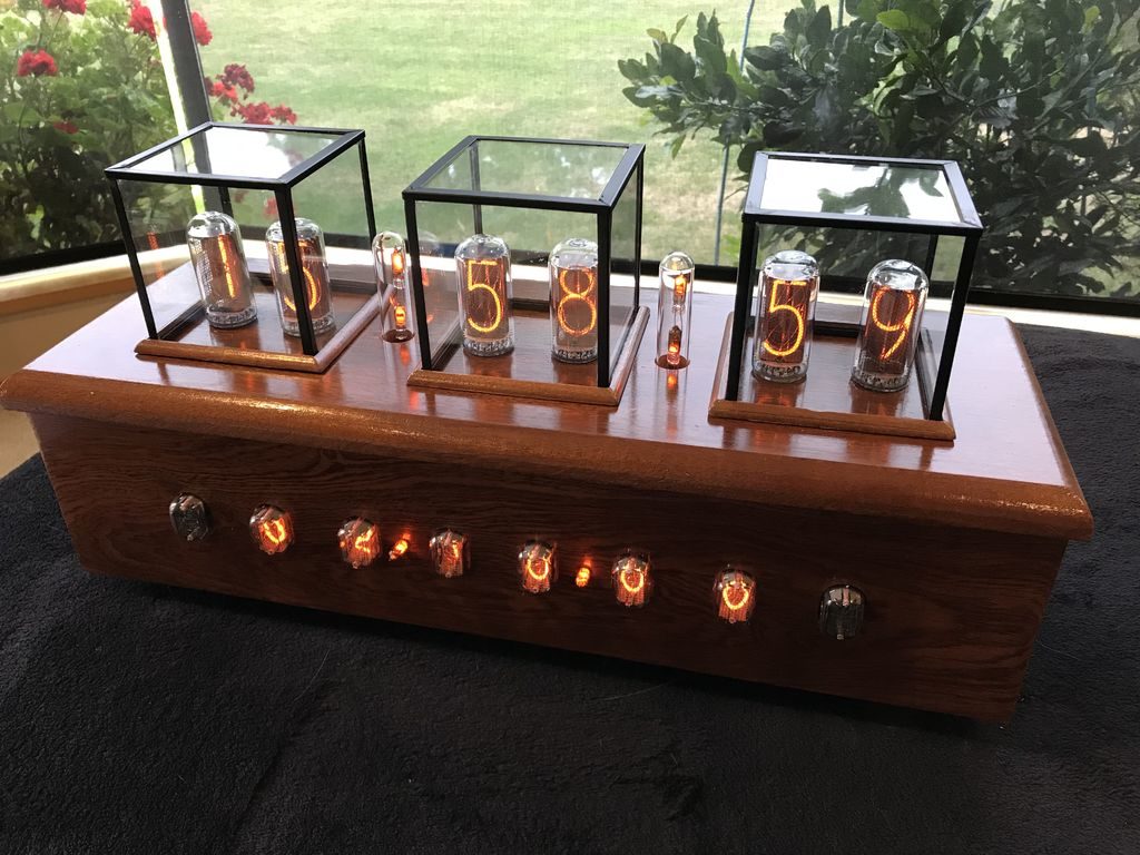
This clock, or perhaps more accurately “info display,” shows the time and date with six IN-18 tubes mounted on the top. In the front, six IN-12A and two IN-15A tubes are also available to show time, date, pressure, temperature, and humidity.

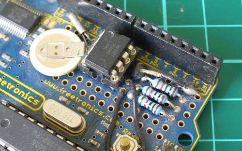
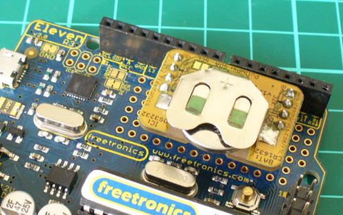
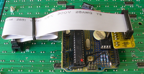
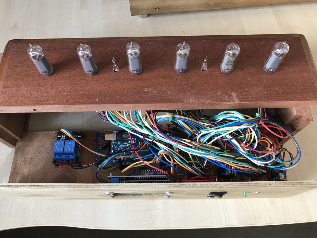
A pair of Arduino Mega boards are used to control this retro-inspired contraption, along with an array of wiring, perf board, and other components, stuffed inside a very nice wooden enclosure. 

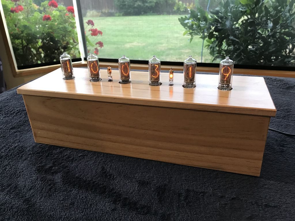
This is my first Nixie styled clock I have constructed. The clock actually consists of two clocks, the first being a 6 x IN-18 tube clock which is mounted on the clock’s top and displays both time and date. The second clock, this time based on 6 x IN-12A and 2 x IN-15A nixie tubes displays at the front of the clock and can display, time, date, pressure (with units and trend), temperature (both Centigrade and Fahrenheit) and, humidity (with units and trend). The time and date are separated with two single neon lamp-based separators, while only one of these lamps is displayed, to represent a decimal point, when the pressure, humidity or temperature is displayed. Both these clocks use “Direct/Static Drive” to power the displays and are based on two Arduino Mega 2560 boards. The fourteen tubes are driven by 12V to 170V DC to DC boost power supplies and 14 x K155 IC chips. The clock also powers two sets of Neon Lamps which switch off while the clock goes through its cathode cleaning cycle which happens at 19, 39 and 55 minutes past each hour. This cathode cleaning cycle consists of all six tubes displaying the digits 0 through 9 in sequence 6 times.

In addition the clock will sound a chime at 15, 30, 45 and 60 minutes. At the 60 minute chime the hour chime is also sounded. The chimes are standard MP3 files using a simple MP3 player controlled by the Arduino mega. In order to save on tube life all tubes are switched off automatically when the light level in the room dims to a predefined level, this is achieved using a LRD resistor located at the back of the clock. To help dissipate any heat build up both Arduino Mega ICs have copper heat fins attached and a 5V fan draws air out of the clock, cool air entering through a hole in the bottom plate.

The user can adjust the time, date, chimes, and chimes volume using one of two 16×2 LCD displays, located at the back of the clock. The BME280 temperature, humidity, and pressure sensor is mounted on the back of the clock so as to not be affected by the clock’s internal temperature.

A demo is seen in the video below, while more info and Arduino code can be found in the project’s write-up.

A brilliant clock made out of 128 LED-lit ping pong balls

Ping pong balls have long been known as excellent LED diffusers, but few have taken this technique as far as Thomas Jensma. His colorful clock features 128 LEDs, arranged in an alternating pattern, and housed in a stretched-out hexagonal wood frame. 

For control, the device uses an Arduino Nano, along with a RTC module for accurate timekeeping. Demos of the clock can be seen below, cycling through numbers and testing out the FastLED library.

Code for the build is available in Jensma’s write-up. This also includes tips on using table tennis balls as diffusers, as well as how to create an orderly array out of these spheres—useful in a wide range of projects.

Telling the Time with Robots, Lasers, and Phosphorescence

What's cooler than a clock that draws the time with a marker? One that does it with a laser of course! Build your own.

Read more on MAKE

The post Telling the Time with Robots, Lasers, and Phosphorescence appeared first on Make: DIY Projects and Ideas for Makers.

New Project: 3D Print a Supersized Seven-Segment Clock

Building your own clock is practically a rite of passage as a Maker. 3D-print this Arduino-based desktop clock with a jumbo seven-segment LED display that glows from within.

Read more on MAKE

The post 3D Print a Supersized Seven-Segment Clock appeared first on Make: DIY Projects, How-Tos, Electronics, Crafts and Ideas for Makers.

What time is it? Explore Galileo board’s real time clock tutorial

In the past weeks we explored how to make a gsm-controlled star light, a touch-screen controlled marionette, and how to learn more about Linux on Intel Galileo Gen 2.

In today’s tutorial  you’ll learn how to create a “Wake up clock” which will turn on and illuminate the room slowly, simulating a morning sunrise. And hopefully, it will make waking up on Mondays a bit easier!

This is the bill of materials:

Intel® Galileo Gen 2 power supply
Arduino Protoshield
LED power supply
1 High power white LED(3v 700mA)
1 1000 ?F Capacitor
1 2.1 mm DC jack-to-screw terminal adaptor
1 10k potentiometer

1 1.8Ohm 2w resistor
1 LM317t voltage regulator
2 10kOhm resistor
1 2n7000 transistor
1 Coin battery holder
Jumper wires
Colored wire
Pin header
1 8 mm magnet
Stiff wire (that is attracted to magnets)
Wood glue
Hot glue sticks
4 mm MDF components – lasercut according to drawing
Plexiglas components – lasercut according to drawing
Nuts and bolts
Rubberband

Download the files and learn how to assemble electronics at this link

Various 1 Hz Oscillator Methods

Introduction

During the fun and enjoyment of experimenting with electronics there will come a time when you need a nice 1 Hz oscillator to generate a square-wave signal to drive something in the circuit. On… off… on… off… for all sorts of things. Perhaps a metronome, to drive a TTL clock, blink some LEDs, or for more nefarious purposes. No matter what you need that magic 1 Hz for – there’s a variety of methods to generate it – some more expensive than others – and some more accurate than others.

A few of you may be thinking “pull out the Arduino” and yes, you could knock out a reasonable 1 Hz – however that’s fine for the bench, but wild overkill for embedding a project as a single purpose. So in this article we’ll run through three oscillator methods that can generate a 1 Hz signal (and other frequencies) using methods that vary in cost, accuracy and difficulty – and don’t rely on mains AC. That will be a topic for another day.

Using a 555 timer IC

You can solve this problem quite well for under a dollar with the 555, however the accuracy is going to heavily rely on having the correct values for the passive components. We’ll use the 555 in astable mode, and from a previous article here’s the circuit:

 And with a 5V power supply, here’s the result:

As you can see the cycle time isn’t the best, which can be attributed to the tolerance of the resistors and capacitor C1. A method to increase the accuracy would be to add small trimpots in series with the resistors (and reduce their value accordingly by the trimpot value) – then measure the output with a frequency counter (etc). whilst adjusting the trimpots. If you’re curious about not using C2, the result of doing so introduces some noise on the rising edge, for example:

So if you’ve no other option, or have the right values for the passives – the 555 can do the job. Or get yourself a 555 and experiment with it, there’s lots of fun to be had with it.

Using a GPS receiver module

A variety of GPS modules have a one pulse per second output (PPS) and this includes my well-worn EM406A module (as used in the Arduino tutorials):

With a little work you can turn that PPS output into a usable and incredibly accurate source of 1 Hz. As long as your GPS can receive a signal. In fact, this has been demonstrated in the April 2013 edition of Silicon Chip magazine, in their frequency counter timebase project. But I digress.

If you have an EM406A you most likely have the cable and if not, get one to save your sanity as the connector is quite non-standard. If you’re experimenting a breakout board will also be quite convenient, however you can make your own by just chopping off one end of the cable and soldering the required pins – for example:

You will need access to pins 6, 5, 2 and 1. Looking at the socket on the GPS module, they are numbered 6 to 1 from left to right. Pin 6 is the PPS output, 5 is GND, 2 is for 5V and 1 is GND. Both the GNDs need to be connected together.

Before moving forward you’re probably curious about the pulse, and want to see it. Good idea! However the PPS signal is incredibly quick and has an amplitude of about 2.85 V. If you put a DSO on the PPS and GND output, you can see the pulses as shown below:

 To find the length of the pulse, we had to really zoom in to a 2 uS timebase:

 Wow, that’s small. So a little external circuitry is required to convert that minuscule pulse into something more useful and friendly. We’ll increase the pulse length by using a “pulse stretcher”. To do this we make a monostable timer (“one shot”) with a 555. For around a half-second pulse we’ll use 47k0 for R1 and 10uF for C1. However this triggers on a low signal, so we first pass the PPS signal through a 74HC14 Schmitt inverter – a handy part which turns irregular signals into more sharply defined ones – and also inverts it which can then be used to trigger the monostable. Our circuit:

 and here’s the result – the PPS signal is shown with the matching “stretched” signal on the DSO:

So if you’re a stickley for accuracy, or just want something different for portable or battery-powered applications, using the GPS is a relatively simple solution.

Using a Maxim DS1307/DS3232 real-time clock IC

Those of you with a microcontroller bent may have a Maxim DS1307 or DS3232. Apart from being pretty easy to use as a real-time clock, both of them have a programmable square wave output. Connection via your MCU’s I2C bus is quite easy, for example with the DS1307:

Using a DS3232 is equally as simple. We use a pre-built module with a similar schematic. Once you have either of them connected, the code is quite simple. For the DS1307 (bus address 0x68), write 0x07 then 0x11 to the I2C bus – or for the DS3232 (bus address is also 0x68) write 0x0E then 0x00. Finally, let’s see the 1 Hz on the DSO:

Certainly not the cheapest method, however it gives you an excellent level of accuracy without the GPS.

Conclusion

By no means is this list exhaustive, however hopefully it was interesting and useful. If there’s any other methods you’d like to see demonstrated, leave a comment below and we’ll see what’s possible. And if you made it this far – check out my new book “Arduino Workshop” from No Starch Press.

In the meanwhile have fun and keep checking into tronixstuff.com. Why not follow things on twitterGoogle+, subscribe  for email updates or RSS using the links on the right-hand column? And join our friendly Google Group – dedicated to the projects and related items on this website. Sign up – it’s free, helpful to each other –  and we can all learn something.

The post Various 1 Hz Oscillator Methods appeared first on tronixstuff.

Tronixstuff 31 Jul 14:07
1 hz  555  74hc14  astable  clock  clocks  digital  ds1307  ds3232  em406a  gps  logic  pps  timebase  tronixstuff  ttl  tutorial  

Book – “Arduino Workshop – A Hands-On Introduction with 65 Projects”

Over the last few years I’ve been writing a few Arduino tutorials, and during this time many people have mentioned that I should write a book. And now thanks to the team from No Starch Press this recommendation has morphed into my new book – “Arduino Workshop“:

Although there are seemingly endless Arduino tutorials and articles on the Internet, Arduino Workshop offers a nicely edited and curated path for the beginner to learn from and have fun. It’s a hands-on introduction to Arduino with 65 projects – from simple LED use right through to RFID, Internet connection, working with cellular communications, and much more.

Each project is explained in detail, explaining how the hardware an Arduino code works together. The reader doesn’t need any expensive tools or workspaces, and all the parts used are available from almost any electronics retailer. Furthermore all of the projects can be finished without soldering, so it’s safe for readers of all ages.

The editing team and myself have worked hard to make the book perfect for those without any electronics or Arduino experience at all, and it makes a great gift for someone to get them started. After working through the 65 projects the reader will have gained enough knowledge and confidence to create many things – and to continue researching on their own. Or if you’ve been enjoying the results of my thousands of hours of work here at tronixstuff, you can show your appreciation by ordering a copy for yourself or as a gift

You can review the table of contents, index and download a sample chapter from the Arduino Workshop website.

Arduino Workshop is available from No Starch Press in printed or ebook (PDF, Mobi, and ePub) formats. Ebooks are also included with the printed orders so you can get started immediately.

In the meanwhile have fun and keep checking into tronixstuff.com. Why not follow things on twitterGoogle+, subscribe  for email updates or RSS using the links on the right-hand column? And join our friendly Google Group – dedicated to the projects and related items on this website. Sign up – it’s free, helpful to each other –  and we can all learn something.

The post Book – “Arduino Workshop – A Hands-On Introduction with 65 Projects” appeared first on tronixstuff.

Project: Clock Four – Scrolling text clock

Introduction

Time for another instalment in my highly-irregular series of irregular clock projects.  In this we have “Clock Four” – a scrolling text clock. After examining some Freetronics Dot Matrix Displays in the stock, it occurred to me that it would be neat to display the time as it was spoken (or close to it) – and thus this the clock was born. It is a quick project – we give you enough to get going with the hardware and sketch, and then you can take it further to suit your needs.

Hardware

You’ll need three major items – An Arduino Uno-compatible board, a real-time clock circuit or module using either a DS1307 or DS3232 IC, and a Freetronics DMD. You might want an external power supply, but we’ll get to that later on.

The first stage is to fit your real-time clock. If you are unfamiliar with the operation of real-time clock circuits, check out the last section of this tutorial. You can build a RTC circuit onto a protoshield or if you have a Freetronics Eleven, it can all fit in the prototyping space as such:

If you have an RTC module, it will also fit in the same space, then you simply run some wires to the 5V, GND, A4 (for SDA) and A5 (for SCL):

By now I hope you’re thinking “how do you set the time?”. There’s two answers to that question. If you’re using the DS3232 just set it in the sketch (see below) as the accuracy is very good, you only need to upload the sketch with the new time twice a year to cover daylight savings (unless you live in Queensland). Otherwise add a simple user-interface – a couple of buttons could do it, just as we did with Clock Two. Finally you just need to put the hardware on the back of the DMD. There’s plenty of scope to meet your own needs, a simple solution might be to align the control board so you can access the USB socket with ease – and then stick it down with some Sugru:

With regards to powering the clock – you can run ONE DMD from the Arduino, and it runs at a good brightness for indoor use. If you want the DMD to run at full, retina-burning brightness you need to use a separate 5 V 4 A power supply. If you’re using two DMDs – that goes to 8 A, and so on. Simply connect the external power to one DMD’s terminals (connect the second or more DMDs to these terminals):

The Arduino Sketch

You can download the sketch from here. Please use IDE v1.0.1 . The sketch has the usual functions to set and retrieve the time from DS1307/3232 real-time clock ICs, and as usual with all our clocks you can enter the time information into the variables in void setup(), then uncomment setDateDs1307(), upload the sketch, re-comment setDateDs1307, then upload the sketch once more. Repeat that process to re-set the time if you didn’t add any hardware-based user interface.

Once the time is retrieved in void loop(), it is passed to the function createTextTime(). This function creates the text string to display by starting with “It’s “, and then determines which words to follow depending on the current time. Finally the function drawText() converts the string holding the text to display into a character variable which can be passed to the DMD.

And here it is in action:

Conclusion

This was a quick project, however I hope you found it either entertaining or useful – and another random type of clock that’s easy to reproduce or modify yourself. We’re already working on another one which is completely different, so stay tuned.

In the meanwhile have fun and keep checking into tronixstuff.com. Why not follow things on twitterGoogle+, subscribe  for email updates or RSS using the links on the right-hand column? And join our friendly Google Group – dedicated to the projects and related items on this website. Sign up – it’s free, helpful to each other –  and we can all learn something.

The post Project: Clock Four – Scrolling text clock appeared first on tronixstuff.

TicTocTrac: track your perception of time

Brian Schiffer and Sima Mitra, from Cornell University, propose a very nice wristwatch that allows you to keep track of your time perception, using a method known as duration production: TicTocTrac.

Human perception of time is typically distorted, due to the different amount of information and experiences acquired everyday. TicTocTrac lets you to estimate your own perception, first by signaling the perceived duration of a given event and, then, by comparing it with the actual event duration. Finally, all the information can easily be saved to a micro SD card.

The hardware is based on a Atmega32u4, a DS3234S real-time clock and several leds to display time, while the software part is mostly based on Arduino’s DS3234S RTC library.

More information can be found here.

[Via: TicTocTrac]