Over at [Truthlabs], a 30 year old pinball machine was diagnosed with a major flaw in its game design: It could only entertain one person at a time. [Dan] and his colleagues set out to change this, transforming the ol’ pinball legend “Firepower” into a spectacular, immersive gaming experience worthy of the 21st century.
A major limitation they wanted to overcome was screen size. A projector mounted to the ceiling should turn the entire wall behind the machine into a massive 15-foot playfield for anyone in the room to enjoy.
With so much space to fill, the team assembled a visual concept tailored to blend seamlessly with the original storyline of the arcade classic, studying the machine’s artwork and digging deep into the sci-fi archives. They then translated their ideas into 3D graphics utilizing Cinema4D and WebGL along with the usual designer’s toolbox. Lasers and explosions were added, ready to be triggered by game interactions on the machine.
To hook the augmentation into the pinball machine’s own game progress, they elaborated an elegant solution, incorporating OpenCV and OCR, to read all five of the machine’s 7 segment displays from a single webcam. An Arduino inside the machine taps into the numerous mechanical switches and indicator lamps, keeping a Node.js server updated about pressed buttons, hits, the “Lange Change” and plunged balls.
The result is the impressive demonstration of both passion and skill you can see in the video below. We really like the custom shader effects. How could we ever play pinball without them?
[JAC_101], the Director of Legal Evil Emeritus for LVL1 Hackerspace (don’t ask me, it’s their title system), was challenged to a hacking duel. It all started years ago. The person who is now president of LVL1, visited the space for the first time and brought with her a discarded Apple II controller for Lego bricks which had previously belonged to her father. Excited to test it, the space found that, unfortunately, LVL1’s Apple II wouldn’t boot. An argument ensued, probably some trash talking, and [JAC_101] left with the challenge: Could he build an Arduino interface for the Apple II Lego controller quicker than the hackerspace could fix its Apple II?”
Other things that belonged to people’s fathers.
In the end, a concentrated force by one hacker over two years overcame the collective ADHD of many. He began by opening the interface to look inside, a completely unnecessary step since he found it was already thoroughly documented. Next he forgot about the project for a year. Then he remembered it, and built an interface for an Arduino Uno to hook to the controller and wrote a library for the interface. Realizing that sending serial commands was not in line with the original friendly intention of the device, he added a graphical display to the project; which allowed the user to control the panel with touch. In the end he won the challenge and LVL1 still doesn’t have a working Apple II. We assume some gloating occurred. Some videos of it in action after the break.
Over on hackaday.io, [Arduino Enigma] posted the code for his clock that runs on a KIM Uno (the KIM-1 clone we mentioned late last year). Although the KIM Uno has a few demos preloaded (including Microchess and a scientific calculator), all of them take some interaction. The clock makes the KIM Uno a more dynamic desk display since it does something useful without any user interaction (once you set the clock, of course).
The project shows the code stored in ROM, but you can’t directly enter the program into ROM (which is really EEPROM on the host Arduino). The trick is to enter the address (that is press AD and then 0, 4, 0, 0) and then mash down the reset button for about a second. Then you can press DA and enter the hex codes provided (pressing + after each byte). Since the code is in nonvolatile storage, you can start it at any time by setting the time in RAM and executing the code at address 400.
The program is short and sweet, making it is easy to enter and a great opportunity to brush up on understanding your 6502. However, the simplicity means it doesn’t range check your initial time settings, so don’t tell it that it is 32:99 or something like that. The code isn’t commented, but it is pretty simple, once you realize one thing: the first instruction, SED, sets the 6502’s decimal mode so no conversion between hex and decimal is needed.
Each part of the time (hours, minutes, and seconds) is stored in RAM at locations 0024, 0025, and 0026. The NEXTD routine uses the X register to scan through each part of the time, adding 1 or 0 as appropriate (stored in RAM location 0029). If the time part matches the corresponding table entry at CARRYT (that is, 60, 60, or 24 also indexed by the X register), then the code does not take the branch to CONTIN and reloads the increment (location 0029) with zero, so the next digits will not advance. If it does match, the increment stays as 1 and the current part returns to a zero value.
You may notice the time is stored back to locations starting at 0024 and 00F9. That’s because 00F9 is where the KIM-1 ROM looks for data to write to the display when calling the ROM-resident subroutine at 1F1F. The X register ranges from 0 to 2, corresponding to the seconds, minutes, and hours. Once all the time is updated, the loop at L1 displays the time and delays for about one second.
A neat piece of coding and a great example of the power of the 6502’s decimal mode. This would look even better with [Scott’s] enhanced version of the KIM-1 UNO.
Microcontrollers existed before the Arduino, and a device that anyone could program and blink an LED existed before the first Maker Faire. This might come as a surprise to some, but for others PICs and 68HC11s will remain as the first popular microcontrollers, found in everything from toys to microwave ovens.
Arduino can’t even claim its prominence as the first user-friendly microcontroller development board. This title goes to the humble Basic Stamp, a four-component board that was introduced in the early 1990s. I recently managed to get my hands on an original Basic Stamp kit. This is the teardown and introduction to the first user friendly microcontroller development boards. Consider it a walk down memory lane, showing us how far the hobbyist electronics market has come in the past twenty year, and also an insight in how far we have left to go.
The Basic Stamp 1. A Simple circuit with just a microcontroller, an EEPROM, crystal, and brownout circuit.
Teardown
The Basic Stamp kit on my workbench was made in 1993, and sold for a suggested retail price of $139 USD. Adjusted for inflation, this is nearly $230 in 2015 dollars. What do you get in the Basic Stamp starter kit? A single stamp, a programmer cable, and a surprising amount of documentation.
The Basic Stamp is an extremely minimalist board that does just enough to blink an LED, read a button, or drive an LCD. In the official documentation, there are only a handful of parts: a microcontroller, an EEPROM with a few bytes of memory, a crystal, and a voltage regulator.
The PIC16C56XL is the brains of the outfit, featuring 1.5kilobits of Flash memory and 25 bytes of RAM. By modern standards, it’s tiny; the closest modern analog would be the ATtiny10, itself not a very recent chip. Microchip’s smallest and newest chip is the PIC12LF1522, featuring twice as much Flash and ten times the amount of RAM. We’re dealing with an old microcontroller when using the Basic Stamp
Like the Arduino, it was encouraged to use the Basic Stamp in product design.
Other components include a 93LC56 serial EEPROM. beside that is a 4MHz regulator, a 5V linear regulator, and a transistor and a few resistors for the ‘brown out’ circuit. Power is provided by a 9V battery connector soldered onto the board.
The electronic design of the Basic Stamp is simple, yes, but there’s a method to the madness. The code you write for the Basic Stamp is stored in 256 bytes of the EEPROM. This code is read by a PBASIC interpreter on the PIC, dutifully following commands to blink a LED or display a character on an LCD. No user code is actually stored on the microcontroller.
Programming
How about the programming environment? That’s a single executable running in a DOS shell. The system requirements are only, an IBM PC or compatible, DOS 2.0+, 128k of RAM, and a disk drive. Meager requirements, but this is not something that will run on your modern Windows workstation; it requires a proper parallel port.
For an IDE, the Basic Stamp editor is comparable to earlier Arduino IDEs; Alt+R runs the program on the Stamp connected to the computer, Alt+L loads a program, Alt+S saves a program, and Alt+Q quits the editor.
The BASIC language implemented on the PIC is minimal, but it does everything you would expect; individual pins can be set as input and output, buttons are debounced, and PWM functions are baked into the language.
An ad for the Basic Stamp. From High Tech Entrepreneur, October/November 1993. Ads had text in the past.
Context
The Basic Stamp is now regarded as a slow, inconvenient artifact from the past. No one uses it, and the only place you’ll find one is in the back cabinet in a physics or EE classroom. This is an incredible disservice to a still-impressive piece of technology, and looking back at the Basic Stamp with our modern expectations is an incredible bias.
There were microcontroller development platforms before the Basic Stamp, but these were engineering tools, and expensive compared to the Stamp. Development platforms for the electrical hobbyist were around after the stamp, too: the Micromint Domino packed an entire development platform into a rectangular brick of plastic. None of these designs could match the popularity of the Basic Stamp despite the platform’s shortcomings.
The Arduino receives a lot of hate. Detractors say it’s too high-level for proper embedded programming, not high-level enough for a modern workflow, is based on old, obsolete chips, doesn’t have the features of modern ARM microcontrollers, and the IDE is a mess. Despite an even less capable IDE, meager memory, and a slow processor, the Basic Stamp proved incredibly popular. The fact that you could pick up a Basic Stamp development kit at any Radio Shack probably didn’t hurt it’s popularity, either.
Now, with our fancy IDEs, mbed microcontrollers, powerful ARMs, and huge libraries, the ease of use of the Basic Stamp has still not been equaled. It may be slow, outdated, but all of us owe a great debt to the Basic Stamp for introducing an entire generation to the world of embedded programming, microcontrollers, and electronics tinkering.
We’ve seen a growing number of posts and recommendations around the net regarding components, specifically transistors. “Don’t use old parts” they cry, “Go with newer components.” You can often find these recommendations on Arduino forums. This all came to a head with a page called “Do Not TIP,” which was linked in the Arduino subreddit. This page belongs to [Tom Jennings], creator of Fidonet, and one of the early authors of what would become Phoenix BIOS. [Tom] and a few others have been calling for everyone to send their old parts to the landfill – not use them, nor gift them to new experimenters. Get them out of the food chain. No offense to [Tom], but we have to disagree. These parts are still perfectly usable for experienced designers, and have a lot to offer new hardware hackers.
TIP is the part number prefix for a series of power transistors created by Texas Instruments. In fact, “TIP” stands for Texas Instruments Power. The series was originally released in 1969. Yes, that’s right, 1969. Why are we still using parts designed when man first walked on the moon? The same reason people are still using the 555 timer: they’re simple, they’re easily available, they’re robust, and most of all, they get the job done. The TIP series has been used in thousands of classes, tutorials both online and off, and millions of projects over the years. Much of that documentation is already out there on the internet. The TIP series is also out in the distribution channel – they’ve been used for 40 years. Any retail shop that stocks a few electronics parts will have at least one of the TIP series.
The TIP series aren’t always the best transistors for the job. However, for most hobbyist-designed circuits, we don’t need the best performance, nor the best price – we’re going to use the parts we have on hand. There is always room to improve once you get the basic circuit working.
In [Tom’s] specific example, he’s using a TIP120 to control a motor at 5 volts drawing 1 amp of current. [Tom’s] big problem with the TIP120 is that it’s inefficient when running the motor. That’s because the TIP120 isn’t a transistor. It’s two transistors configured as a Darlington pair. Like everything else in life, Darlington pairs have trade offs. To achieve high gain, you end up with higher voltage drop. In high current designs, that translates into heat. In this case, 2 watts of heat, which [Tom] claims will result in melted parts and fire. It turns out that the datasheet shows 2 watts is the upper limit for thermal dissipation on the TIP120’s TO-220 case. It will get very hot, but it will not catch fire. Want to be on the safe side? Add a heatsink, which is as easy as attaching a piece of metal using the convenient screw hole in the TO-220 case.
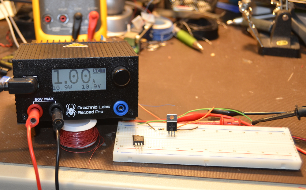
Just for fun, we created our own version of [Tom’s] example. We connected a TIP120 to a 12V lab supply. Rather than connect a motor, we grabbed our Re:Load Pro and set it for 1 amp. We use a 680 ohm base resistor to ensure the TIP120 was in saturation. The Re:Load Pro indicated that it was indeed seeing 1 amp of current flow, at 10.9 volts. This means that the TIP120 was only dropping 1.1V, rather than the 2V quoted on the datasheet. Were we just lucky? We tried a few TIP120s we had around the lab from a couple of manufacturers, and all of them were pretty close – well below the worst case 2V. Obviously you can’t design beyond the specs called on in the datasheet, but sometimes things work out in your favor. With the current set to 1 amp, the math is easy. The Re:Load Pro was converting 10.9 watts of power to heat. The TIP120 was dissipating 1.1 watts. The TIP120 did get hot – we measured up to 60°C. But it never went beyond that. A heatsink would have cooled things down, but we were shooting for worst case scenario. We ran this setup for 2 hours and there was no smoke, fire, or failure.
Can you do better with a different part? Absolutely. [Tom] suggests a MOSFET such as the NTD4906N. FETs are great, we use them all the time. However, they come with a completely different set of rules and pitfalls compared to BJTs. Learning the rules, the design trade offs and pitfalls of both families of devices are key factors when learning electronics design. Every component a designer learns is a new color on their design palette. On the code side we worry about people becoming “cut and paste” coders. The same thing happens on the hardware side when a designer doesn’t learn how to use different types of parts.
So don’t throw away your old parts. Use them, learn from them, and become a better designer for it!
[Chris Gregg] had a dream. He wanted to convert use a typewriter as a printer. Sure this has been done before, but [Chris] wanted to create his own version. He picked up a 60’s era Smith Corona electric typewriter, with the hopes of driving its key switches with a computer. You can imagine his surprise when he discovered the keys were not electric switches at all, but a complex mechanical system which triggered a clutch to strike the actual paper. Realizing this was not going to be a simple wiring job, [Chris] set the project aside, where it remained for several years.
A conversation with [Bruce Molay], a coworker at Tufts University reignited [Chris’] interest in project. [Bruce] suggested using solenoids to press the keys. [Chris] dove in, and quickly had 48 solenoids on hand. The first problem was mounting the solenoids on the keys. [Chris’] roommate happens to be [Derek Seabury], president of Artisan’s Asylum Hackerspace. [Derek] created an acrylic frame which holds the solenoids and fits directly over the typewriter’s keyboard. This meant that no modifications needed to be made to the typewriter itself. Simply lift off the solenoid array and you’re ready to rock like it’s 1965.
The next step was driving all those solenoids. For that, Chris worked with [Kate Wasynczuk], one of his students at Tufts. [Chris] designed a board using Texas Instruments TPIC6A595 shift registers. The TIPC “power logic” series work like regular 74 series logic, but have seriously beefy outputs. These chips can handle up to 50 volts and 1.5 amps pulsed output current – plenty for [Chris’] 24 volt solenoids. [Chris] taught himself schematic entry and PCB layout in Eagle. After only two tries, he had a working board from OSHPark.
An Arduino Uno converts serial over USB output to a bit stream ready to clock into the shift registers. On the computer side, [Chris] wrote up a basic CUPS driver which allows him to print from his Macbook. The perfect demo for this project turned out to be musical. Click past the break to see The Smith Corona perform “The Typewriter Symphony”, by Leroy Anderson. This may be the first time this particular piece of music has been performed with actual words being typed, rather than random keys.
Here’s a classic version of “The Typewriter Symphony”
It appears a very important anniversary passed by recently without anyone realizing. The January 1975 issue of Popular Electronics featured the Altair 8800 on the cover, otherwise known as the blinky box that launched a revolution, the machine that made Microsoft a software powerhouse, and the progenitor of the S-100 bus. The 40-year anniversary of the Altair wasn’t forgotten by [dankar], who built a front panel emulator with the help of some much more modern components.
The build unofficially began with an Intel 8080 emulator written for an Arduino. The 8080 is the brains of the Altair, and while emulators are cool, they don’t have the nerd cred of a panel of switches and LEDs. The hardware began as a bunch of perfboard, but [dankar] wired himself into a corner and decided to make a real schematic and PCB in KiCAD.
Despite the banks of LEDs and switches, there really isn’t much to this front panel. Everything is controlled by shift registers, but there is a small amount of SRAM in the form of an SPI-capable 23LC1024. This comes in handy, because [dankar] is running CP/M 2.2 on this front panel emulator from disk images saved on an SD card. Everything you would want from a computer from 1975 is there; an OS, BASIC, and enough I/O to attach some peripherals.
The KIM-1 was the first computer to use the 6502, a CPU that would later be found in the Apple, Ataris, Commodores, and the Nintendo Entertainment System. Being the first, the KIM-1 didn’t actually do a whole lot with only 1k of ROM and a bit more than 1k of RAM. This is great news for anyone with an Arduino; you can easily replicate an entire KIM-1, with a keypad and 7-segment display. That’s what [Scott] did, and he put it in an enclosure that would look right at home in a late 70s engineering lab.
The impetus for this build was [Scott]’s discovery of the KIM-Uno, a kit clone of the KIM-1 using an Arduino Pro Mini. The kit should arrive in a few weeks, so until then he decided to see if he could cobble one together with parts he had sitting around.
Inside a handheld industrial enclosure is an Arduino Uno, with a protoshield connecting the keypad and display. The display is an 11-digit, seven-segment display [Scott] picked up at a surplus shop, and the metal dome keypad came from a hamfest.
Getting the software working took a bit of work, but the most important parts are just modifications to the standard Arduino libraries.
Now that [Scott] has a KIM-1 replica, he can program this virtual 6502 one hex digit at a time, run Microchess, or use the entire thing as a programmable calculator.
[Gary Kildall] and CP/M are the great ‘also ran’ of the computing world; CP/M could run on thousands of different 1980s computers, and [Gary] saw a few million in revenue each year thanks to CP/M’s popularity. Microsoft, DOS, and circumstances have relegated [Kildall] and CP/M to a rather long footnote in the history of microcomputers, but that doesn’t mean CP/M is completely dead yet. [Marcelo] wrote a Z80 emulator running CP/M inside an Arduino Due, and he did it in such a way that it’s actually convenient and useful to use.
Instead of using CP/M disk images, [Marcelo]’s emulator emulates CP/M disk drives on top of a regular FAT file system. Drives are mapped to folders in the FAT file system, so a folder named ‘A’ will show up as the A: disk in CP/M. Drives up to P: are supported, the maximum number of drives available under CP/M. The BIOS resides in the root directory of the SD card, and so far Microsoft Basic, Turbo Pascal, UCD Micromumps, and Wordstar work just fine.
The Arduino project was built upon one of [Marcelo]’s earlier projects that put the CP/M emulator on Windows. The version for the Due works exactly how you think it would, with a serial connection and terminal emulator providing the IO, and the huge amount of processing power and RAM available on the Due doing all the heavy lifting.
[Christopher Mitchell] has given Texas Instruments calculators the ability to capture images through a Game Boy Camera with ArTICam. First introduced in 1998, The Game Boy Camera was one of the first low-cost digital cameras available to consumers. Since then it has found its way into quite a few projects, including this early Atmel AT90 based hack, and this Morse code transceiver.
TI calculators don’t include a Game Boy cartridge slot, so [Christopher] used an Arduino Uno to interface the two. He built upon the Arduino-TI Calculator Linking (ArTICL) Library to create ArTICam. Getting the Arduino to talk with the Game Boy Camera’s M64282FP image sensor turned out to be easy, as there already are code examples available. The interface between the camera sensor and the Arduino is simple enough. 6 digital lines for an oddball serial interface, one analog sense line, power and ground. [Christopher] used a shield to solder everything up, but says you can easily get away with wiring directly the Arduino Uno’s I/O pins. The system is compatible with the TI-83 Plus and TI-84 Plus family of calculators. Grabbing an image is as simple as calling GetCalc(Pic1) from your calculator program.
So, If you have an old calculator lying around, give it a try to enjoy some 128×123-pixel grayscale goodness!